EP1388429A2 - Thermal dye transfer print bearing patterned overlayer and process for making same - Google Patents
Thermal dye transfer print bearing patterned overlayer and process for making same Download PDFInfo
- Publication number
- EP1388429A2 EP1388429A2 EP03077365A EP03077365A EP1388429A2 EP 1388429 A2 EP1388429 A2 EP 1388429A2 EP 03077365 A EP03077365 A EP 03077365A EP 03077365 A EP03077365 A EP 03077365A EP 1388429 A2 EP1388429 A2 EP 1388429A2
- Authority
- EP
- European Patent Office
- Prior art keywords
- dye
- overlayer
- thermal
- expandable microspheres
- Prior art date
- Legal status (The legal status is an assumption and is not a legal conclusion. Google has not performed a legal analysis and makes no representation as to the accuracy of the status listed.)
- Granted
Links
Classifications
-
- B—PERFORMING OPERATIONS; TRANSPORTING
- B41—PRINTING; LINING MACHINES; TYPEWRITERS; STAMPS
- B41J—TYPEWRITERS; SELECTIVE PRINTING MECHANISMS, i.e. MECHANISMS PRINTING OTHERWISE THAN FROM A FORME; CORRECTION OF TYPOGRAPHICAL ERRORS
- B41J2/00—Typewriters or selective printing mechanisms characterised by the printing or marking process for which they are designed
- B41J2/315—Typewriters or selective printing mechanisms characterised by the printing or marking process for which they are designed characterised by selective application of heat to a heat sensitive printing or impression-transfer material
- B41J2/32—Typewriters or selective printing mechanisms characterised by the printing or marking process for which they are designed characterised by selective application of heat to a heat sensitive printing or impression-transfer material using thermal heads
- B41J2/325—Typewriters or selective printing mechanisms characterised by the printing or marking process for which they are designed characterised by selective application of heat to a heat sensitive printing or impression-transfer material using thermal heads by selective transfer of ink from ink carrier, e.g. from ink ribbon or sheet
-
- B—PERFORMING OPERATIONS; TRANSPORTING
- B41—PRINTING; LINING MACHINES; TYPEWRITERS; STAMPS
- B41M—PRINTING, DUPLICATING, MARKING, OR COPYING PROCESSES; COLOUR PRINTING
- B41M7/00—After-treatment of prints, e.g. heating, irradiating, setting of the ink, protection of the printed stock
- B41M7/0027—After-treatment of prints, e.g. heating, irradiating, setting of the ink, protection of the printed stock using protective coatings or layers by lamination or by fusion of the coatings or layers
-
- G—PHYSICS
- G09—EDUCATION; CRYPTOGRAPHY; DISPLAY; ADVERTISING; SEALS
- G09F—DISPLAYING; ADVERTISING; SIGNS; LABELS OR NAME-PLATES; SEALS
- G09F3/00—Labels, tag tickets, or similar identification or indication means; Seals; Postage or like stamps
- G09F3/02—Forms or constructions
-
- G—PHYSICS
- G09—EDUCATION; CRYPTOGRAPHY; DISPLAY; ADVERTISING; SEALS
- G09F—DISPLAYING; ADVERTISING; SIGNS; LABELS OR NAME-PLATES; SEALS
- G09F3/00—Labels, tag tickets, or similar identification or indication means; Seals; Postage or like stamps
- G09F3/08—Fastening or securing by means not forming part of the material of the label itself
- G09F3/10—Fastening or securing by means not forming part of the material of the label itself by an adhesive layer
-
- Y—GENERAL TAGGING OF NEW TECHNOLOGICAL DEVELOPMENTS; GENERAL TAGGING OF CROSS-SECTIONAL TECHNOLOGIES SPANNING OVER SEVERAL SECTIONS OF THE IPC; TECHNICAL SUBJECTS COVERED BY FORMER USPC CROSS-REFERENCE ART COLLECTIONS [XRACs] AND DIGESTS
- Y10—TECHNICAL SUBJECTS COVERED BY FORMER USPC
- Y10T—TECHNICAL SUBJECTS COVERED BY FORMER US CLASSIFICATION
- Y10T428/00—Stock material or miscellaneous articles
- Y10T428/24—Structurally defined web or sheet [e.g., overall dimension, etc.]
- Y10T428/24802—Discontinuous or differential coating, impregnation or bond [e.g., artwork, printing, retouched photograph, etc.]
Definitions
- the invention relates to a thermal dye transfer print comprising a protective overlayer including a polymeric binder containing dispersed heat expandable microspheres wherein the expandable microspheres have been selectively expanded in a predetermined pattern.
- U.S. Patent No. 6, 092, 942 (Koichi et al.) includes a thermal dye donor element composed of a yellow, magenta and cyan dye patch plus a protective overlayer which is applied to the receiver layer containing the printed image by means of a thermal print head.
- the protective layer is applied by using an image plane as a mask as opposed to a uniform application of energy down the page.
- the protective layer image is designed to have low and high energy arranged in a pattern to produce corresponding regions of density in the transferred protective layer.
- the final pattern in the transferred protective layer imparts a satin or matte like appearance to the surface of the dye receiver by changing the thickness of the protective layer.
- the use of a protective layer made in this manner limits the coarseness of the texture that can be applied.
- U.S. Patent 6,346,502 (Simpson et al.) and UK Patent Specification 2,348,509 (Lum et al.) teach the use of expandable microspheres in a protective layer to impart a satin or matte finish to dye-diffusion thermal transfer prints.
- the application of heat during transfer of the protective layer from the donor element to the receiver layer causes the microspheres, which are filled with an easily vaporized fluid, to expand in size.
- the larger size microspheres scatter light more efficiently giving the appearance of a satin or matte finish to the print.
- the level of gloss may be controlled by the amount of heat applied to the layer.
- Application of the protective layer can be done with a thermal print head or other devices, such as a heated roller.
- the invention provides a thermal dye transfer print bearing a protective overlayer comprising a polymeric binder containing dispersed heat expandable microspheres wherein the expandable microspheres have been selectively expanded in a predetermined pattern.
- the invention also provides a process for making such prints.
- the invention enables a broad range of patterned textures to be applied to the overlayer.
- patterned means a macroscopic pattern in which the pattern present in one square centimeter is not the same as in every other square centimeter of the overlayer.
- Microspheres means generally spheroidal or ellipsoidal shaped beads of expandable material.
- the invention encompasses a thermal dye transfer print bearing a protective overlayer comprising a polymeric binder containing dispersed heat expandable microspheres wherein the expandable microspheres have been selectively expanded in a predetermined pattern and a process for making the same.
- the print of the invention is one wherein the pattern is a macroscopic textile-like repeating pattern.
- the pattern is an information-bearing pattern especially one that is machine readable or is humanly readable visually or by touch.
- the protective overlayer may further suitably comprise inorganic particles such as silica particles.
- the print of the invention encompasses overlayer arrangements wherein the microspheres are selectively expanded or not depending on a macroscopic location and wherein the microspheres are selectively expanded by various degrees of expansion depending on location.
- the print of the invention includes overlayer arrangements wherein the protective overlayer additionally comprises an IR absorbing dye or where the thickness of the protective overlayer varies.
- the process for forming the overlayer on a thermal dye transfer print comprises:
- the heat is applied via a thermal print head, especially one where the thermal print head is variable as to which pixels are energized and/or the extent to which pixels are energized.
- the thermal print head used to heat the protective overlayer is desirably a separate print head from that used to transfer the imaging dye.
- the overlayer contains an IR dye and the heat is applied via selective application of a laser beam.
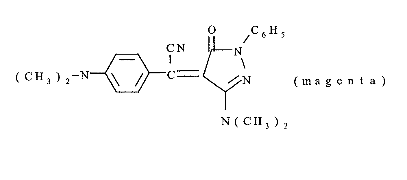
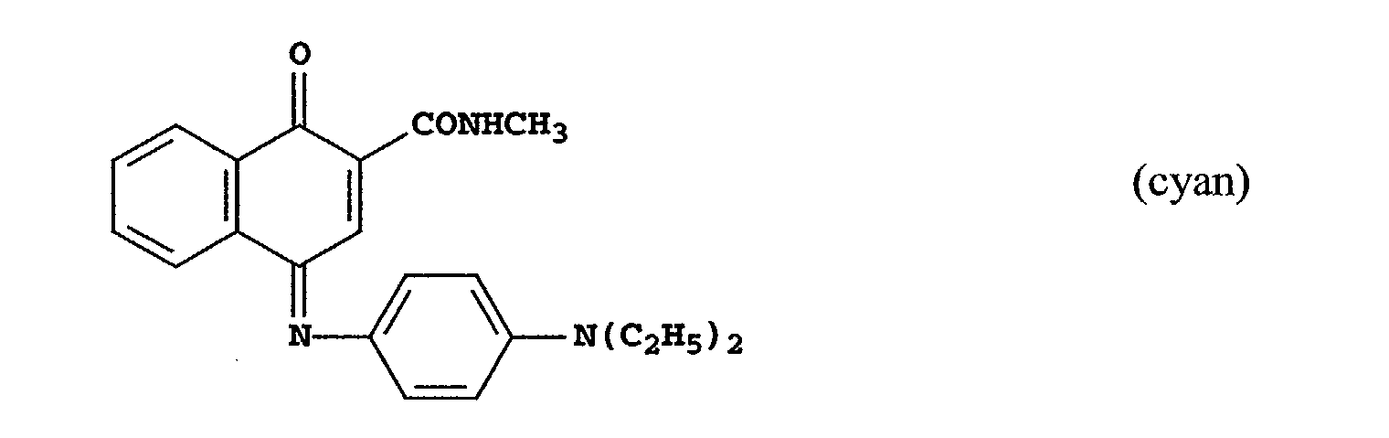
- any dye can be used in the dye layer of the dye-donor element of the invention provided it is transferable to the dye-receiving layer by the action of heat.
- sublimable dyes include anthraquinone dyes, e.g., Sumikaron Violet RS® (Sumitomo Chemical Co., Ltd.), Dianix Fast Violet 3R FS® (Mitsubishi Chemical Industries, Ltd.), and Kayalon Polyol Brilliant Blue N BGM® and KST Black 146® (Nippon Kayaku Co., Ltd.); azo dyes such as Kayalon Polyol Brilliant Blue BM®, Kayalon Polyol Dark Blue 2BM®, and KST Black KR® (Nippon Kayaku Co., Ltd.), Sumikaron Diazo Black 5G® (Sumitomo Chemical Co., Ltd.), and Miktazol Black 5GH® (Mitsui Toatsu Chemicals, Inc.); direct dyes such as Direct Dark Green
- the above dyes maybe employed singly or in combination to obtain a monochrome.
- the dyes may be used at a coverage of from about 0.05 to about 1 g/m 2 and are preferably hydrophobic.
- a dye-barrier layer may be employed in the dye-donor elements of the invention to improve the density of the transferred dye.
- Such dye-barrier layer materials include hydrophilic materials such as those described and claimed in U.S. Patent 4,716,144.
- the dye layers and protection layer of the dye-donor element may be coated on the support or printed thereon by a printing technique such as a gravure process.
- a slipping layer may be used on the back side of the dye-donor element of the invention to prevent the printing head from sticking to the dye-donor element.
- a slipping layer would comprise either a solid or liquid lubricating material or mixtures thereof, with or without a polymeric binder or a surface-active agent.
- Preferred lubricating materials include oils or semicrystalline organic solids that melt below 100°C such as poly(vinyl stearate), beeswax, perfluorinated alkyl ester polyethers, poly-caprolactone, silicone oil, poly(tetrafluoroethylene), carbowax, poly(ethylene glycols), or any of those materials disclosed in U.S.
- Suitable polymeric binders for the slipping layer include poly(vinyl alcohol-co-butyral), poly(vinyl alcohol-co-acetal), polystyrene, poly(vinyl acetate), cellulose acetate butyrate, cellulose acetate propionate, cellulose acetate or ethyl cellulose.
- the amount of the lubricating material to be used in the slipping layer depends largely on the type of lubricating material, but is generally in the range of about 0.001 to about 2 g/m 2 . If a polymeric binder is employed, the lubricating material is present in the range of 0.05 to 50 weight %, preferably 0.5 to 40 weight %, of the polymeric binder employed.
- any material can be used as the support for the dye-donor element of the invention provided it is dimensionally stable and can withstand the heat of the thermal printing heads.
- Such materials include polyesters such as poly(ethylene terephthalate); polyamides; polycarbonates; glassine paper; condenser paper; cellulose esters such as cellulose acetate; fluorine polymers such as poly(vinylidene fluoride) or poly(tetrafluoroethylene-co-hexafluoropropylene); polyethers such as polyoxymethylene; polyacetals; polyolefins such as polystyrene, polyethylene, polypropylene or methylpentene polymers; and polyimides such as polyimide amides and polyetherimides.
- the support generally has a thickness of from about 2 to about 30 ⁇ m.
- the dye-receiving element that is used with the dye-donor element of the invention usually comprises a support having thereon a dye image receiving layer.
- the support may be a transparent film such as a poly(ether sulfone), a polyimide, a cellulose ester such as cellulose acetate, a poly(vinyl alcohol-co-acetal) or a poly(ethylene terephthalate).
- the support for the dye-receiving element may also be reflective such as baryta-coated paper, polyethylene-coated paper, white polyester (polyester with white pigment incorporated therein), an ivory paper, a condenser paper or a synthetic paper such as DuPont Tyvek®.
- the dye image-receiving layer may comprise, for example, a polycarbonate, a polyurethane, a polyester, poly(vinyl chloride), poly(styrene-co-acrylonitrile), polycaprolactone or mixtures thereof.
- the dye image-receiving layer may be present in any amount which is effective for the intended purpose. In general, good results have been obtained at a concentration of from about 1 to about 5 g/m 2 .
- the dye donor elements of the invention are used to form a dye transfer image.
- Such a process comprises imagewise heating a dye-donor element as described above and transferring a dye image to a dye receiving element to form the dye transfer image. After the dye image is transferred, the protection layer is then transferred on top of the dye image.
- the dye donor element of the invention may be used in sheet form or in a continuous roll or ribbon. If a continuous roll or ribbon is employed, it may have only one dye or may have alternating areas of other different dyes, such as sublimable cyan and/or magenta and/or yellow and/or black or other dyes. Such dyes are disclosed in U.S. Patents 4,541,830; 4,698,651; 4,695,287; 4,701,439; 4,757,046; 4,743,582; 4,769,360 and 4,753,922. Thus, one-, two-, three- or four-color elements (or higher numbers also) are included within the scope of the invention.
- the dye-donor element comprises a poly(ethylene terephthalate) support coated with sequential repeating areas of yellow, cyan and magenta dye, and the protection layer noted above, and the above process steps are sequentially performed for each color to obtain a three-color dye transfer image with a protection layer on top.
- a monochrome dye transfer image is obtained.
- Thermally expandable microspheres or beads such as those manufactured as Expancel® by Expancel, Inc., having an average diameter of from six to seventeen micrometers can be used to impart a matte or textured finish within the scope of this invention. An average diameter of from six to nine micrometers in the unexpanded state is preferable. Also, it is preferable that the polymeric wall of the microsphere have a softening temperature between 95 and 130 °C and be resistant to attack by solvents commonly used in the preparation of solutions for gravure coating.
- Thermal printing heads which can be used to transfer dye from the dye-donor elements of the invention, are available commercially. There can be employed, for example, a Fujitsu Thermal Head FTP-040 MCSOO1, a TDK Thermal Head LV5416 or a Rohm Thermal Head KE 2008-F3.
- a thermal dye transfer assemblage of the invention comprises
- the above assemblage comprising these two elements may be preassembled as an integral unit when a monochrome image is to be obtained. This may be done by temporarily adhering the two elements together at their margins. After transfer, the dye-receiving element is then peeled apart to reveal the dye transfer image.
- the above assemblage is formed on three occasions during the time when heat is applied by the thermal printing head. After the first dye is transferred, the elements are peeled apart. A second dye-donor element (or another area of the donor element with a different dye area) is then brought in register with the dye-receiving element and the process is repeated. The third color is obtained in the same manner. Finally, the protection layer is applied on top.
- the receiver element consisted of three layers coated on Eastman Kodak Electronic print paper support as described in U.S. Ppatent Nos. 5,858,916 and 5,858,919. Since the important interaction for successful transfer of a protective layer takes place between the protective layer and the topmost layer of the receiver element, the support of the latter acts only as a carrier of the receiver layers and may consist of any material compatible with the bottom-most receiver layer.
- the first layer which was coated directly on the support consisted of 0.1076 g/m 2 Prosil 221, an aminopropyltriethoxysilane, (PCR, Inc.), 0.1076 g/m 2 Prosil 2210, a proprietary epoxy trialkoxy silane, (PCR, Inc.) and LiCl (0.0022 g/m 2 ) in an ethanol-methanol-water solvent mixture.
- the second layer consisted of Makrolon KL3-1013 (Bayer AG) at 1.52 g/m 2 ,Lexan 141-112 polycarbonate (General Electric Co.) at 1.24 g/m 2 , FC431(3M Corp.) at 0.011 g/m 2 , Drapex® 429 polyester plasticizer (Witco Corp) (0.23 g/m 2 ), 8 ⁇ m crosslinked poly(styrene-co-butyl acrylate-co-divinylbenzene) elastomeric beads (Eastman Kodak Co.) (0.006 g/m 2 ) and diphenylphthalate at 0.46 g/m from dichloromethane.
- the third, and topmost layer of the receiver element consisted of a copolymer of 50 mole-% bisphenol A, 49 mole-% diethylene glycol and 1 mole-% of a poly(dimethylsiloxane) block at a laydown of 0.55 g/m 2 , FC431 at 0.022 g/m 2 , and DC510 silicone fluid surfactant (Dow Corning) at 0.003 g/m 2 .
- Protective layer donor elements were prepared by coating on 6 ⁇ m PET (poly(ethylene terephthalate)) support:
- an image plane in the form of a checkerboard pattern was created from individual pixels by selecting the size of the individual squares in the checkerboard to be one or more pixels (eg.- nine pixels/ square).
- the applied energy was adjusted through the digital value assigned to the number of pulses.
- the TDK 3K0345 thermal print head has 2560 independently addressable heaters with a resolution of 300 dots/inch and an average resistance of 3314 ⁇ .
- the imaging electronics were activated when an initial print head temperature of 36.4°C had been reached.
- the assemblage was drawn between the printing head and platen roller at 16.9 mm/sec.
- the resistive elements in the thermal print head were pulsed on for 58 ⁇ sec every 76 ⁇ sec.
- Printing maximum density required 64 pulses "on" time per printed line of 5.0 msec.
- the voltage supplied was 13.6 volts resulting in an instantaneous peak power of approximately 58.18 x 10⁻³ Watt/dot and the maximum total energy required to print Dmax was 0.216 mJoules/dot.
- the process is repeated sequentially, yellow, magenta, cyan to obtain the desired neutral image.
- Table 1 show that, when a texture pattern is printed onto an overprotective layer containing thermally expandable microspheres, an improvement in the level of texture is observed when compared to an over-protective layer with no expandable beads.
- Table 2 show that less metallic appearance is observed when thermally expandable microspheres are included in the over-protective laminate.
Landscapes
- Physics & Mathematics (AREA)
- General Physics & Mathematics (AREA)
- Engineering & Computer Science (AREA)
- Theoretical Computer Science (AREA)
- Thermal Transfer Or Thermal Recording In General (AREA)
- Accessory Devices And Overall Control Thereof (AREA)
- Electronic Switches (AREA)
Abstract
Description



| Texture Applied to Status A Maximum and Minimum Density | ||||
| Transferable Overcoat | Image Density | Digital Print Values | Size Pixel Area | Texture Rating |
| C-1 | Dmax | 0, 100 | 3x6 | 0 |
| Invention 1 | Dmax | 0, 100 | 3 x 6 | + |
| C-1 | Dmin | 0, 100 | 3 x 6 | 0 |
| Invention 1 | Dmin | 0, 100 | 3 X 6 | + |
| 0 = no texture + = obvious texture |
| Improvement of Metallic Appearance | ||||
| Transferable Overcoat | Image Density | Digital Print Values | Size Pixel Area | Metallic Appearance |
| C-1 | Dmax | 0, 255 | 9 x 9 | - |
| Invention 1 | Dmax | 0, 255 | 9 x 9 | + |
| C-1 | Dmin | 0, 255 | 9 x 9 | - |
| Invention 1 | Dmin | 0, 255 | 9 x 9 | + |
| + = No metallic appearance | ||||
| - = A metallic appearance |
Claims (10)
- A thermal dye transfer print bearing a protective overlayer comprising a polymeric binder containing dispersed heat expandable microspheres wherein the expandable microspheres have been selectively expanded in a predetermined pattern.
- The print of claim 1 wherein the protective overlayer comprises inorganic particles.
- The print of claim 1 wherein the microspheres are selectively expanded or not depending on microsphere location.
- The print of claim 1 wherein the microspheres are selectively expanded by various degrees of expansion and depending on location.
- The print of claim 1 wherein the protective overlayer additionally comprises an IR absorbing dye.
- A process for forming an overlayer on a thermal dye transfer print comprising:1) applying to the print a solid sheet comprising a polymeric binder containing dispersed heat expandable microspheres;2) applying heat selectively to the surface of the overlayer sheet so that the expandable microspheres are selectively expanded in a predetermined pattern.
- The process of claim 6 wherein the heat is applied via a thermal print head.
- The process of claim 7 wherein the thermal print head is variable as to which pixels are energized.
- The process of claim 7 wherein the thermal print head is variable as to the extent to which pixels are energized.
- The process of claim 14 wherein overlayer contains an IR dye and the heat is applied via selective application of a laser beam.
Applications Claiming Priority (2)
| Application Number | Priority Date | Filing Date | Title |
|---|---|---|---|
| US213991 | 2002-08-07 | ||
| US10/213,991 US6759369B2 (en) | 2002-08-07 | 2002-08-07 | Thermal dye transfer print bearing patterned overlayer and process for making same |
Publications (3)
| Publication Number | Publication Date |
|---|---|
| EP1388429A2 true EP1388429A2 (en) | 2004-02-11 |
| EP1388429A3 EP1388429A3 (en) | 2004-09-15 |
| EP1388429B1 EP1388429B1 (en) | 2006-01-25 |
Family
ID=30443714
Family Applications (1)
| Application Number | Title | Priority Date | Filing Date |
|---|---|---|---|
| EP03077365A Expired - Lifetime EP1388429B1 (en) | 2002-08-07 | 2003-07-29 | Thermal dye transfer print bearing patterned overlayer and process for making same |
Country Status (4)
| Country | Link |
|---|---|
| US (2) | US6759369B2 (en) |
| EP (1) | EP1388429B1 (en) |
| JP (1) | JP2004066828A (en) |
| DE (1) | DE60303337T2 (en) |
Families Citing this family (5)
| Publication number | Priority date | Publication date | Assignee | Title |
|---|---|---|---|---|
| EP1388428B1 (en) * | 2002-08-07 | 2005-10-05 | Eastman Kodak Company | Thermal transfer printing method |
| US7923412B1 (en) * | 2004-02-12 | 2011-04-12 | Kazdin Richard H | Creating background colors on thermal printing material |
| US7852359B2 (en) * | 2007-10-31 | 2010-12-14 | Eastman Kodak Company | Protective overcoat transfer compensation |
| US9106696B2 (en) * | 2009-04-15 | 2015-08-11 | Wyse Technology L.L.C. | Method and apparatus for portability of a remote session |
| CN104752347B (en) * | 2013-12-25 | 2017-11-14 | 清华大学 | The preparation method of organic LED array |
Family Cites Families (20)
| Publication number | Priority date | Publication date | Assignee | Title |
|---|---|---|---|---|
| US4541830A (en) * | 1982-11-11 | 1985-09-17 | Matsushita Electric Industrial Co., Ltd. | Dye transfer sheets for heat-sensitive recording |
| US4716144A (en) * | 1985-12-24 | 1987-12-29 | Eastman Kodak Company | Dye-barrier and subbing layer for dye-donor element used in thermal dye transfer |
| US4701439A (en) * | 1985-12-24 | 1987-10-20 | Eastman Kodak Company | Yellow dye-donor element used in thermal dye transfer |
| US4717712A (en) * | 1985-12-24 | 1988-01-05 | Eastman Kodak Company | Lubricant slipping layer for dye-donor element used in thermal dye transfer |
| US4695287A (en) * | 1985-12-24 | 1987-09-22 | Eastman Kodak Company | Cyan dye-donor element used in thermal dye transfer |
| US4698651A (en) * | 1985-12-24 | 1987-10-06 | Eastman Kodak Company | Magenta dye-donor element used in thermal dye transfer |
| US4757046A (en) * | 1986-10-06 | 1988-07-12 | Eastman Kodak Company | Merocyanine dye-donor element used in thermal dye transfer |
| US4743582A (en) * | 1986-10-06 | 1988-05-10 | Eastman Kodak Company | N-alkyl-or n-aryl-aminopyrazolone merocyanine dye-donor element used in thermal dye transfer |
| US4738950A (en) * | 1987-06-16 | 1988-04-19 | Eastman Kodak Company | Amino-modified silicone slipping layer for dye-donor element used in thermal dye transfer |
| US4769360A (en) * | 1987-09-14 | 1988-09-06 | Eastman Kodak Company | Cyan dye-donor element for thermal dye transfer |
| US4753922A (en) * | 1987-11-20 | 1988-06-28 | Eastman Kodak Company | Neutral-black dye-donor element for thermal dye transfer |
| JPH04103360A (en) | 1990-08-23 | 1992-04-06 | Victor Co Of Japan Ltd | Transfer method of heat melting transparent binder |
| US5392059A (en) * | 1991-05-13 | 1995-02-21 | Dai Nippon Printing Co., Ltd. | Image forming method using thermal transfer |
| US5369419A (en) * | 1992-06-24 | 1994-11-29 | Eastman Kodak Company | Method and apparatus for marking a receiver media with specularly differentiated indicia |
| US5568177A (en) * | 1995-04-03 | 1996-10-22 | At&T Global Information Solutions Company | Thermal transfer printing ribbon for printing security bar code symbols |
| KR100453369B1 (en) | 1996-04-25 | 2005-09-12 | 소니 가부시끼 가이샤 | Printing apparatus, printing method, image forming apparatus and image forming method |
| US6164849A (en) * | 1997-08-27 | 2000-12-26 | Sony Corporation | Gloss control apparatus and method |
| JP3668598B2 (en) | 1997-09-17 | 2005-07-06 | 三菱電機株式会社 | Recording method and apparatus |
| GB2348509A (en) | 1998-11-18 | 2000-10-04 | Eastman Kodak Co | Dye-donor element with a transferable protection overcoat |
| US6346502B1 (en) | 2000-04-19 | 2002-02-12 | Eastman Kodak Company | Dye-donor element with transferable protection overcoat |
-
2002
- 2002-08-07 US US10/213,991 patent/US6759369B2/en not_active Expired - Fee Related
- 2002-12-05 US US10/310,519 patent/US6790477B2/en not_active Expired - Lifetime
-
2003
- 2003-07-29 EP EP03077365A patent/EP1388429B1/en not_active Expired - Lifetime
- 2003-07-29 DE DE60303337T patent/DE60303337T2/en not_active Expired - Lifetime
- 2003-08-07 JP JP2003289007A patent/JP2004066828A/en active Pending
Also Published As
| Publication number | Publication date |
|---|---|
| JP2004066828A (en) | 2004-03-04 |
| US6759369B2 (en) | 2004-07-06 |
| US6790477B2 (en) | 2004-09-14 |
| US20040028880A1 (en) | 2004-02-12 |
| EP1388429A3 (en) | 2004-09-15 |
| EP1388429B1 (en) | 2006-01-25 |
| DE60303337T2 (en) | 2006-10-19 |
| DE60303337D1 (en) | 2006-04-13 |
| US20040029732A1 (en) | 2004-02-12 |
Similar Documents
| Publication | Publication Date | Title |
|---|---|---|
| US5006502A (en) | Heat transfer sheet | |
| US5387573A (en) | Thermal dye transfer dye-donor element with transferable protection overcoat containing particles | |
| US6184181B1 (en) | Process for controlling the gloss of a thermal dye transfer image | |
| US7018772B2 (en) | Method of transferring a protective overcoat to a dye-donor element | |
| US6759369B2 (en) | Thermal dye transfer print bearing patterned overlayer and process for making same | |
| EP1186438B1 (en) | Dye-donor element containing transferable protection overcoat | |
| EP1147914B1 (en) | Dye-donor element with transferable protection overcoat | |
| US5514637A (en) | Thermal dye transfer dye-donor element containing transferable protection overcoat | |
| US6942956B2 (en) | Process of transferring transferable protection overcoat to a dye-donor element | |
| US5866506A (en) | Assemblage and Process for thermal dye transfer | |
| US5830824A (en) | Plasticizers for dye-donor element used in thermal dye transfer | |
| US5350732A (en) | Subbing layer for dye-donor element used in thermal dye transfer | |
| GB2348509A (en) | Dye-donor element with a transferable protection overcoat | |
| US5352653A (en) | Crosslinked dye-donor binder for thermal dye transfer systems | |
| EP1216840B1 (en) | Dye-donor element with transferable protection overcoat | |
| US20040001952A1 (en) | Protective laminate and process for thermal dye sublimation prints | |
| JP3450016B2 (en) | Composite thermal transfer sheet | |
| JP3217855B2 (en) | Dye receiving layer transfer sheet and composite thermal transfer sheet |
Legal Events
| Date | Code | Title | Description |
|---|---|---|---|
| PUAI | Public reference made under article 153(3) epc to a published international application that has entered the european phase |
Free format text: ORIGINAL CODE: 0009012 |
|
| AK | Designated contracting states |
Kind code of ref document: A2 Designated state(s): AT BE BG CH CY CZ DE DK EE ES FI FR GB GR HU IE IT LI LU MC NL PT RO SE SI SK TR |
|
| AX | Request for extension of the european patent |
Extension state: AL LT LV MK |
|
| PUAL | Search report despatched |
Free format text: ORIGINAL CODE: 0009013 |
|
| AK | Designated contracting states |
Kind code of ref document: A3 Designated state(s): AT BE BG CH CY CZ DE DK EE ES FI FR GB GR HU IE IT LI LU MC NL PT RO SE SI SK TR |
|
| AX | Request for extension of the european patent |
Extension state: AL LT LV MK |
|
| 17P | Request for examination filed |
Effective date: 20050124 |
|
| AKX | Designation fees paid |
Designated state(s): DE FR |
|
| RBV | Designated contracting states (corrected) |
Designated state(s): DE GB |
|
| GRAP | Despatch of communication of intention to grant a patent |
Free format text: ORIGINAL CODE: EPIDOSNIGR1 |
|
| GRAS | Grant fee paid |
Free format text: ORIGINAL CODE: EPIDOSNIGR3 |
|
| GRAA | (expected) grant |
Free format text: ORIGINAL CODE: 0009210 |
|
| AK | Designated contracting states |
Kind code of ref document: B1 Designated state(s): DE GB |
|
| REG | Reference to a national code |
Ref country code: GB Ref legal event code: FG4D |
|
| REF | Corresponds to: |
Ref document number: 60303337 Country of ref document: DE Date of ref document: 20060413 Kind code of ref document: P |
|
| PLBE | No opposition filed within time limit |
Free format text: ORIGINAL CODE: 0009261 |
|
| STAA | Information on the status of an ep patent application or granted ep patent |
Free format text: STATUS: NO OPPOSITION FILED WITHIN TIME LIMIT |
|
| 26N | No opposition filed |
Effective date: 20061026 |
|
| PGFP | Annual fee paid to national office [announced via postgrant information from national office to epo] |
Ref country code: GB Payment date: 20140624 Year of fee payment: 12 |
|
| REG | Reference to a national code |
Ref country code: DE Ref legal event code: R082 Ref document number: 60303337 Country of ref document: DE Representative=s name: WAGNER & GEYER PARTNERSCHAFT PATENT- UND RECHT, DE |
|
| REG | Reference to a national code |
Ref country code: DE Ref legal event code: R082 Ref document number: 60303337 Country of ref document: DE Representative=s name: WAGNER & GEYER PARTNERSCHAFT MBB PATENT- UND R, DE Effective date: 20141028 Ref country code: DE Ref legal event code: R082 Ref document number: 60303337 Country of ref document: DE Representative=s name: WAGNER & GEYER PARTNERSCHAFT PATENT- UND RECHT, DE Effective date: 20141028 Ref country code: DE Ref legal event code: R081 Ref document number: 60303337 Country of ref document: DE Owner name: KODAK ALARIS INC., ROCHESTER, US Free format text: FORMER OWNER: EASTMAN KODAK COMPANY, ROCHESTER, N.Y., US Effective date: 20141028 |
|
| REG | Reference to a national code |
Ref country code: GB Ref legal event code: 732E Free format text: REGISTERED BETWEEN 20150108 AND 20150114 |
|
| PGFP | Annual fee paid to national office [announced via postgrant information from national office to epo] |
Ref country code: DE Payment date: 20150731 Year of fee payment: 13 |
|
| GBPC | Gb: european patent ceased through non-payment of renewal fee |
Effective date: 20150729 |
|
| PG25 | Lapsed in a contracting state [announced via postgrant information from national office to epo] |
Ref country code: GB Free format text: LAPSE BECAUSE OF NON-PAYMENT OF DUE FEES Effective date: 20150729 |
|
| REG | Reference to a national code |
Ref country code: DE Ref legal event code: R119 Ref document number: 60303337 Country of ref document: DE |
|
| PG25 | Lapsed in a contracting state [announced via postgrant information from national office to epo] |
Ref country code: DE Free format text: LAPSE BECAUSE OF NON-PAYMENT OF DUE FEES Effective date: 20170201 |