EP1388301B1 - Buckle - Google Patents
Buckle Download PDFInfo
- Publication number
- EP1388301B1 EP1388301B1 EP03017927A EP03017927A EP1388301B1 EP 1388301 B1 EP1388301 B1 EP 1388301B1 EP 03017927 A EP03017927 A EP 03017927A EP 03017927 A EP03017927 A EP 03017927A EP 1388301 B1 EP1388301 B1 EP 1388301B1
- Authority
- EP
- European Patent Office
- Prior art keywords
- female member
- male member
- apertures
- anchor
- sections
- Prior art date
- Legal status (The legal status is an assumption and is not a legal conclusion. Google has not performed a legal analysis and makes no representation as to the accuracy of the status listed.)
- Expired - Lifetime
Links
Images


Classifications
-
- A—HUMAN NECESSITIES
- A44—HABERDASHERY; JEWELLERY
- A44B—BUTTONS, PINS, BUCKLES, SLIDE FASTENERS, OR THE LIKE
- A44B11/00—Buckles; Similar fasteners for interconnecting straps or the like, e.g. for safety belts
- A44B11/25—Buckles; Similar fasteners for interconnecting straps or the like, e.g. for safety belts with two or more separable parts
- A44B11/26—Buckles; Similar fasteners for interconnecting straps or the like, e.g. for safety belts with two or more separable parts with push-button fastenings
- A44B11/266—Buckles; Similar fasteners for interconnecting straps or the like, e.g. for safety belts with two or more separable parts with push-button fastenings with at least one push-button acting parallel to the main plane of the buckle and perpendicularly to the direction of the fastening action
-
- Y—GENERAL TAGGING OF NEW TECHNOLOGICAL DEVELOPMENTS; GENERAL TAGGING OF CROSS-SECTIONAL TECHNOLOGIES SPANNING OVER SEVERAL SECTIONS OF THE IPC; TECHNICAL SUBJECTS COVERED BY FORMER USPC CROSS-REFERENCE ART COLLECTIONS [XRACs] AND DIGESTS
- Y10—TECHNICAL SUBJECTS COVERED BY FORMER USPC
- Y10T—TECHNICAL SUBJECTS COVERED BY FORMER US CLASSIFICATION
- Y10T24/00—Buckles, buttons, clasps, etc.
- Y10T24/45—Separable-fastener or required component thereof [e.g., projection and cavity to complete interlock]
- Y10T24/45225—Separable-fastener or required component thereof [e.g., projection and cavity to complete interlock] including member having distinct formations and mating member selectively interlocking therewith
- Y10T24/45471—Projection having movable connection between components thereof or variable configuration
- Y10T24/45524—Projection having movable connection between components thereof or variable configuration including resiliently biased projection component or surface segment
- Y10T24/45529—Requiring manual force applied against bias to interlock or disengage
Definitions
- the present invention relates to a buckle having a male member and a female member, more particularly, to a buckle to be used for connecting and disconnecting the opposite ends of a single strap of a pair of straps.
- Buckles are being used as means for connecting and disconnecting the opposite ends of a single strap of a pair of straps.
- JP 10 211005 a buckle comprising a male member and a female member for receiving and anchoring the male member.
- the male member has a resiliently deformable insertion piece, an anchor surface and an operating section.
- the female member has an anchor-holding surface to be engaged with the anchoring surface of said of said male member and an aperture adapted to expose the operating section of said male member to the outside as the anchor-holding surface is engaged with the anchor surface.
- a buckle conventionally comprises a plug and socket into which the plug is inserted and by which it is held.
- the plug is provided with a plug main body and a pair of insertion pieces arranged in parallel with each other at the respective lateral sides of the plug main body.
- On each of the insertion pieces an insertion guide surface is formed at the front part thereof while an operating section and an anchor surface are formed at respective positions closer to the base section of the insertion piece than the insertion guide surface.
- the socket comprises a socket main body and an insertion hole that is cut through the socket main body and into which the plug is inserted.
- Abutting sections are formed respectively on the lateral walls of and near the insertion hole and adapted to resiliently deform the corresponding respective insertion pieces in (inward) directions that are substantially perpendicular to the direction along which the insertion pieces are inserted as the latter abuts the respective insertion guide surfaces of the plug.
- an anchor-holding surface for holding the anchor surface and an aperture for exposing the operating section of the insertion piece are respectively formed on each lateral wall in area located beyond the respective abutting section as viewed from the insertion hole.
- the user inserts the insertion pieces of the plug into the insertion hole of the socket. Then, the insertion guide surfaces formed at the front ends of the insertion pieces respectively abuts the corresponding abutting sections of the socket and hence, as the insertion pieces are inserted further, they are resiliently deformed toward the inside as viewed from the lateral walls of the insertion hole.
- the user depresses the operating sections exposed to the outside through the respective apertures of the socket toward the inside typically by means of the thumb and one of the fingers to resiliently deform the insertion pieces toward the inside. Then, as a result, the anchor surfaces of the insertion pieces are disengaged from the respective anchor-holding surfaces formed on the socket As the user pulls out the plug from the socket, the former comes out from the latter.
- the apertures of the socket through which the operating sections of the plug are exposed to the outside are formed by obliquely cutting out the front and rear walls from the lateral walls of the periphery of the socket so that consequently the apertures of the lateral walls are made very large.
- the insertion pieces of the plug can be damaged (broken) to undesirably reduce the service life of the buckle.
- a buckle comprising a male member and a female member for receiving and anchoring the male member;
- the male member having a male member main body, a pair of resiliently deformable insertion pieces formed on the male member main body, a pair of anchor surfaces formed on the insertion pieces and a pair of operating sections also formed on the insertion pieces and adapted to resiliently deform the insertion pieces;
- the female member having a female member main body, an insertion hole formed in the female member main body and adapted to receive the insertion pieces of the male member inserted into it, a pair of anchor-holding surfaces formed on the female member main body to be engaged with the anchor surfaces of the male member so as to hold the male member in the female member and a pair of apertures adapted to expose the operating sections of the male member to the outside as the anchor-holding surface are engaged with the anchor surfaces; the aperture being formed by inwardly cutting out the front and rear walls of the periphery of the female member main body having the insertion hole continuously in a curved shape
- the projecting sections are formed at edges of said apertures located remotely from an inlet aperture of said insertion hole, said projecting sections being formed to show a curved profile continuously from edges of cut out areas of the front and rear walls of the female member to the lateral walls to be continuous with the curved apertures.
- Outer surfaces of the operating sections are exposed to the outside of the female member through the apertures and inner sides of the operating sections opposite to the outer surfaces exposed by the apertures are curved to show substantially the same curve as the apertures.
- the user inserts the insertion piece of the male member into the insertion hole of the female member. Then, the anchor surface of the insertion piece is held to the anchor-holding surface of the female member and the male member is anchored to the female member.
- the user depresses the operating section of the male member exposed to the outside through the aperture of the female member to disengage the engaged state of the male member and the female member. Since the aperture of the female member is provided with projecting section, the thumb and the finger of the user depressing the operating section abut the projecting section and therefore cannot go deep into the inside of the female member through the aperture. Thus, the problems of damaged insertion piece and reduced service life are dissolved. In other words, since the insertion piece of the male member is not resiliently deformed to an unnecessary extent, it is scarcely damaged and the service life of the buckle is prolonged.
- the projecting sections are formed at the edges of the apertures located remotely from the inlet aperture of the insertion hole so as to project toward the inlet aperture of the insertion hole.
- the projecting section project toward the edge of the aperture located close to the inlet aperture of the insertion hole from the edge of the aperture remote from the inlet aperture of the insertion hole.
- the anchor-holding surface of a buckle according to the invention is mostly arranged at the edge of the aperture located close to the inlet aperture. Therefore, the projecting section projects toward the anchor-holding surface located close to the inlet aperture of the insertion hole.
- the position of the front end of the thumb and that of the front end of the finger are forced to come close to the anchor-holding surface so that the operating section is depressed by the thumb pad and the finger pad at position located close to the anchor-holding surface of the operating section. Then, the male member can be released from the female member if the operating section is depressed by the thumb and the finger only to a small extent
- the projecting sections projects continuously from positions of the edge of the cut out areas of the front and rear walls located, the positions being remotest from the inlet aperture of the insertion hole and transversal dimensions of the projecting sections are gradually reduced toward the inlet aperture of the insertion hole.
- the transversal dimension of the projecting section as used herein refers to the dimension thereof as observed in a direction intersecting the direction along which the projecting section projects (opposite to the direction along which the male member of the buckle is inserted).
- the expression that the transversal dimension of the projecting section is gradually reduced toward the inlet aperture of the insertion hole as used herein may refer to a state where the projecting section is tapered toward the inlet aperture or a state where the projecting section is pointed
- the thumb and the finger depressing the operating section abut the projecting section, they will not be pressed hard intensively at a point because the projecting section is continuously formed from the edge of the cut out area of the front and rear walls of the female member to the lateral wall. Additionally, since the projecting section is continuously tapered, it shows a sufficient strength and hence is prevented from being damaged.
- the projecting section is formed to show a curved profile continuously from the edge of the cut out area of the front and rear walls of the female member to the lateral wall, if the thumb and the finger depressing the operating section abut the corresponding projecting section, they will not be pressed hard intensively at a point. Additionally, since the projecting section shows a curved profile, it is not likely to be damaged.
- the anchored state in a state where the male member is anchored to the female member, the anchored state can be dissolved by depressing the operating sections of the male member that are exposed to the outside from the apertures of the female member and projecting front ends of the projecting section may be located closer to the inlet aperture of the insertion hole than front ends of the insertion pieces anchored to the inside of the insertion hole.
- the male member has a pair of insertion pieces projecting respectively along the lateral edges of the male body in parallel with each other and the anchor surfaces and the operating sections are arranged respectively on the on the surfaces opposite to the mutually opposing sides the corresponding insertion pieces, whereas the anchor-holding surfaces and the apertures are formed respectively at the oppositely disposed lateral walls of the insertion hole of the female member main body of the female member.
- the male member since the male member has a pair of insertion pieces, on the surfaces opposite to the mutually opposing sides of which the anchor surfaces and the operating sections are arranged respectively, the anchor surfaces formed respectively at the front ends of the paired insertion pieces are held to the corresponding anchor-holding surfaces of the female member when the male member is inserted into the female member.
- the male member can be anchored reliably to the female member.
- the male member can be released easily from the female member because only the operating sections formed on the outer sides of the paired insertion pieces need to be depressed inwardly to release the male member from the female member.
- the male member and the female member are made of synthetic resin as integral entities.
- the male member and the female member can be manufactured at low cost on a mass production basis.
- the male member and the female member are provided respectively with strap fitting slots, through which the corresponding ends of the strap member are passed and to which they are anchored.
- the male member and the female member are provided respectively with strap fitting slots, the male member and the female member can be easily and securely linked to the strap member simply by passing the strap member through the strap fitting slots.
- a buckle according to the invention is easy to use.
- FIGS. 1 through 4 illustrate this embodiment of buckle according to the invention.
- the embodiment of buckle 1 is adapted to connect and disconnect the ends 2, 3 of a strap member and comprises a male member 10 made of synthetic resin as integral entity and a female member 20, which the male member 10 is inserted into and held, also made of synthetic resin as integral entity.
- the material used for forming the male member 10 and the female member 20 is not limited to synthetic resin, it can alternatively be metal or some other appropriate material.
- the male member 10 has a male member main body 11, a pair of insertion pieces 15 projecting respectively from the lateral sides of the male member main body 11 in parallel with each other so as to be resiliently deformable, and a guide piece 19 projecting between and in parallel with the insertion pieces 15.
- the male member main body 11 is provided at a middle section thereof with a strap fitting slot 12, through which the corresponding end 2 of the strap member is passed and to which it is anchored, and at the lateral sides thereof with a pair of abutting sections 14 to which the connecting surface 20A of the female member 20 abuts.
- the strap fitting slot 12 is further divided into two strap fitting apertures 12A, 12B by a link beam 13, which is interposed in the strap fitting slot 12, to regulate the effective length of the strap member.
- the insertion piece 15 is composed of a pair of thin and resilient arm sections 15A integrally formed with and extending from the lateral sides of the respective male member main body 11 and a pair of bulged sections 15B extending respectively from the front ends of the resilient arm sections 15A.
- Each of the bulged sections 15B has an insertion guide surface 16 that is outwardly rounded from an inner position of the base end toward the front end thereof, an operating section 17 that is a mildly outwardly curved surface extended from the front end of the insertion guide surface 16, and an anchor surface 18 extending inwardly from the operating section 17 substantially at a right or acute angle, the insertion guide surface 16, the operating section 17 and the anchor surface 18 being arranged in the mentioned order.
- the guide piece 19 is formed in such a way that its thickness is gradually reduced as it extends from the male member main body 11 toward a middle section thereof and then increased as it extends further from the middle section toward the front end thereof.
- a rectangular hollow section 19A is formed in the guide piece 19 from the rear surface thereof to reduce the volume of the material consumed for the buckle.
- the female member 20 has a female member main body 21.
- the female member main body 21 is provided with a strap fitting slot 22, through which the corresponding end 3 of the strap member is inserted and to which it is anchored, and an insertion hole 23 running all the way from the connecting surface 20A of the female member 20 to be connected to the male member 10 to the strap fitting slot 22, into which the insertion pieces 15 and the guide piece 19 of the male member are inserted.
- the connecting surface 20A of the female member 20 (to be connected to the male member 10) shows an inwardly curved profile that is recessed most at the center.
- the oppositely disposed lateral walls of the insertion hole 23 extending from the inlet aperture of the latter are gradually inwardly inclined toward the remote end of the hole so that, when the insertion pieces are inserted into the insertion hole 23, each of them operates as abutting section 24 that abuts the insertion guide surface 16 of the corresponding insertion piece 15 and resiliently deforms the piece 15 in a direction substantially perpendicular to the inserting direction of the insertion piece 15.
- Apertures 25 that expose the respective operating sections 17 of the male member 10 are formed through the lateral walls of the insertion hole 23 in areas located beyond the respective abutting sections 24 as viewed from the insertion hole 23.
- the apertures 25 are produced by partly and inwardly cutting out the front and rear walls 21B, 21C of the periphery of the female member main body 21 having the insertion hole 23 from the lateral walls 21A. To be more specific, each of the apertures 25 is produced by inwardly cutting out the front and rear walls 21B, 21C from the aperture edges 25A, 25B of the corresponding lateral wall to show an inwardly curved profile.
- the aperture edge 25A that is located closer to the insertion hole 23 than the other aperture edge 25B is provided with an anchor-holding surface 27 that comes to be engaged with the anchor surface 18 of the corresponding insertion piece 15 to anchor the male member 10 to the female member 20, whereas the aperture edge 25B that is located remote from the inlet aperture of the insertion hole 23 is provided with a projecting section 28 that projects toward the aperture of the lateral wall.
- the projecting section 28 has a curved surface defined by lines extending from the edges 25C of the cut out parts of the front and rear walls 21B, 21C and connected to the lateral wall 21A. To be more specific, the projecting section 28 projects toward the aperture edge 25A of the corresponding lateral wall as the defining lines are extended from the edges 25C of the cut out parts of the front and rear walls 21B, 21C and its curved surface is mildly connected to the lateral wall 21A.
- the transversal dimension of the projecting section 28 is large at the base section thereof (at the position indicated by the dotted broken line defining the lower end of L1 in FIG 3 ) and small at the front end section thereof (at the position indicated by the dotted broken line defining the upper end of L1 in FIG 3 ). In other words, the projecting section 28 is tapered toward the front end thereof.
- the height of the projecting section 28 (as indicated by L1 in FIG 3 ), which is the distance L1 from the deepest position of the edges 25C of the cut out parts of the front and rear walls 21B, 21C to the front end of the projecting section 28, is so selected that the thumb or finger depressing the corresponding operating section 17 is not caught by the gap between the projecting section 28 and the insertion guide surface 16 and the operating section 17 of the insertion piece 15.
- each of the operating sections 17 is located inside the contour line connecting the separated parts of the corresponding lateral wall 21A of the female member main body 21.
- the above described embodiment operates in a manner as described below.
- the user inserts the insertion pieces 15 of the male member 10 into the insertion hole 23 of the female member 20.
- the insertion guide surfaces 16 formed at the front ends of the insertion pieces 15 abut the respective abutting sections 24 of the female member 20 so that the insertion pieces 15 are inserted further as they are resiliently deformed in respective directions (inwardly) that are substantially perpendicular to the inserting direction of the insertion pieces 15.
- the resiliently deformed insertion pieces 15 restore the original state so that the anchor surfaces 18 of the insertion pieces 15 are retained by the respective anchor-holding surfaces 27 of the female member 20.
- the male member 10 is anchored to the female member 20.
- the user Inwardly depresses the operating sections 17 formed at the front ends of the respective insertion pieces 15 and projecting from the respective apertures 25 of the female member 20, and by doing so, the insertion pieces 15 of the male member 10 are inwardly and resiliently deformed and hence the anchor surfaces 18 are released from the respective anchor-holding surfaces 27.
- the connection between the male member 10 and the female member 20 can be disconnected by pulling out the male member 10 from the female member 20.
- the depressing thumb and finger of the user abut the projecting sections 28 so that they cannot go deep into the female member 20 through the apertures 25. Therefore, the insertion pieces 15 of the male member 10 are not deformed beyond the necessary level. In other words, the insertion pieces 15 are not damaged and broken unnecessarily so that service life thereof is prolonged.
- the profile of the apertures 25 of the female member 20 of the above described embodiment are produced by partly and inwardly cutting out the front and rear walls 21B, 21C from the aperture edges 25A, 25B of the respective lateral walls to show an inwardly curved profile
- the profile of the apertures 25 is not limited thereto and may alternatively have a different profile.
- they may have a rhombic profile having two linear sides that are in parallel with each other and fall inwardly and downwardly (toward the strap fitting slot 22 of the female member 20) from the aperture edges 25A, 25B of the respective lateral walls as shown in FIG 5 .
- the projecting sections 28 are formed at the aperture edges 25B of the lateral walls simultaneously when the apertures 25 having a rhombic profile are formed.
- the projecting sections 28 have a height L1 that does not allow the thumb and one of the fingers of the user depressing the operating sections 17 to enter the respective gaps between the projecting sections 28 and the insertion guide surfaces 16 and the operating sections 17 of the corresponding insertion pieces 15, it is desirable that the height L1 is determined corresponding to the distance L2 between the aperture edges 25A, 25B of each of the apertures 25 as shown in FIG. 5 . More specifically, it is desirable to select a value for the height L1 corresponding to the value for distance L2, which is set corresponding to the size of the thumb or the fingers of the user for letting the thumb and one of the fingers depressing the projecting sections 28 touch (bridge) the aperture edges 25A, 25B of the respective lateral walls.
- insertion guide surfaces 16 are formed at the front ends of the respective insertion pieces 15 of the above described embodiment, they may alternatively be formed at middle positions of the insertion pieces 15 instead of the front ends.
- anchor-holding surfaces 27 are formed at the aperture edges 25A of the lateral walls of the apertures 25 in the above described embodiment, the positions of the anchor-holding surfaces 27 are not limited thereto. They may alternatively be formed at positions separated from the apertures 25.
- FIG 6 shows a buckle having only a single insertion piece 15. In the illustrated instance, therefore, only a single aperture 25 is formed at a lateral side of the female member 20.
- buckle can find numerous applications including bags. Particularly, it may find suitable applications where the buckle should not be unfastened when tensile force exceeding a predetermined level is applied thereto.
- male member 10 and the female member 20 of the above described embodiment are formed by molding synthetic resin (injection molding or injection/compression molding), they may alternatively be formed by molding metal and the like.
Description
- The present invention relates to a buckle having a male member and a female member, more particularly, to a buckle to be used for connecting and disconnecting the opposite ends of a single strap of a pair of straps.
- Buckles are being used as means for connecting and disconnecting the opposite ends of a single strap of a pair of straps.
- Is is known by
JP 10 211005 - A buckle conventionally comprises a plug and socket into which the plug is inserted and by which it is held. The plug is provided with a plug main body and a pair of insertion pieces arranged in parallel with each other at the respective lateral sides of the plug main body. On each of the insertion pieces, an insertion guide surface is formed at the front part thereof while an operating section and an anchor surface are formed at respective positions closer to the base section of the insertion piece than the insertion guide surface. The socket comprises a socket main body and an insertion hole that is cut through the socket main body and into which the plug is inserted. Abutting sections are formed respectively on the lateral walls of and near the insertion hole and adapted to resiliently deform the corresponding respective insertion pieces in (inward) directions that are substantially perpendicular to the direction along which the insertion pieces are inserted as the latter abuts the respective insertion guide surfaces of the plug. At the same time, an anchor-holding surface for holding the anchor surface and an aperture for exposing the operating section of the insertion piece are respectively formed on each lateral wall in area located beyond the respective abutting section as viewed from the insertion hole.
- With the above described arrangement, to anchor the plug to the socket, the user inserts the insertion pieces of the plug into the insertion hole of the socket Then, the insertion guide surfaces formed at the front ends of the insertion pieces respectively abuts the corresponding abutting sections of the socket and hence, as the insertion pieces are inserted further, they are resiliently deformed toward the inside as viewed from the lateral walls of the insertion hole. When the anchor surfaces of the insertion pieces go beyond the respective anchor-holding surfaces formed in the socket, the anchor surfaces of the insertion pieces that have been resiliently deformed toward the inside restore the original profile as they turned back respectively toward the outsides and consequently the anchor surfaces of the insertion pieces are held by the respective anchor-holding surfaces formed on the socket In this state, the operating sections of the plug are exposed to the outside through the respective apertures of the socket.
- To release the plug from the socket, the user depresses the operating sections exposed to the outside through the respective apertures of the socket toward the inside typically by means of the thumb and one of the fingers to resiliently deform the insertion pieces toward the inside. Then, as a result, the anchor surfaces of the insertion pieces are disengaged from the respective anchor-holding surfaces formed on the socket As the user pulls out the plug from the socket, the former comes out from the latter.
- In the above described conventional buckle, the apertures of the socket through which the operating sections of the plug are exposed to the outside are formed by obliquely cutting out the front and rear walls from the lateral walls of the periphery of the socket so that consequently the apertures of the lateral walls are made very large.
- As a result, when the user depresses the operating sections of the plug exposed to the outside through the apertures of the socket by means of the thumb and one of the fingers, they go unnecessarily deep into the inside of the socket through the respective apertures to resiliently deform the insertion pieces of the plug to an unnecessary large extent.
- Then, the insertion pieces of the plug can be damaged (broken) to undesirably reduce the service life of the buckle.
- Therefore, it is a principal object of the present invention to provide a buckle that dissolves the problems of damaged insertion piece and reduced service life.
- According to the invention, the above object is achieved by providing a buckle comprising a male member and a female member for receiving and anchoring the male member; the male member having a male member main body, a pair of resiliently deformable insertion pieces formed on the male member main body, a pair of anchor surfaces formed on the insertion pieces and a pair of operating sections also formed on the insertion pieces and adapted to resiliently deform the insertion pieces; the female member having a female member main body, an insertion hole formed in the female member main body and adapted to receive the insertion pieces of the male member inserted into it, a pair of anchor-holding surfaces formed on the female member main body to be engaged with the anchor surfaces of the male member so as to hold the male member in the female member and a pair of apertures adapted to expose the operating sections of the male member to the outside as the anchor-holding surface are engaged with the anchor surfaces; the aperture being formed by inwardly cutting out the front and rear walls of the periphery of the female member main body having the insertion hole continuously in a curved shape from edges of the lateral wall on which the anchor-holding surfaces provided, said apertures being provided at peripheral edge thereof with projecting sections projecting toward the apertures.
- The projecting sections are formed at edges of said apertures located remotely from an inlet aperture of said insertion hole, said projecting sections being formed to show a curved profile continuously from edges of cut out areas of the front and rear walls of the female member to the lateral walls to be continuous with the curved apertures. Outer surfaces of the operating sections are exposed to the outside of the female member through the apertures and inner sides of the operating sections opposite to the outer surfaces exposed by the apertures are curved to show substantially the same curve as the apertures.
- With the above described arrangement; to anchor the male member to the female member, the user inserts the insertion piece of the male member into the insertion hole of the female member. Then, the anchor surface of the insertion piece is held to the anchor-holding surface of the female member and the male member is anchored to the female member.
- To release the male member that has been inserted into and anchored to the female member from the latter, the user depresses the operating section of the male member exposed to the outside through the aperture of the female member to disengage the engaged state of the male member and the female member. Since the aperture of the female member is provided with projecting section, the thumb and the finger of the user depressing the operating section abut the projecting section and therefore cannot go deep into the inside of the female member through the aperture. Thus, the problems of damaged insertion piece and reduced service life are dissolved. In other words, since the insertion piece of the male member is not resiliently deformed to an unnecessary extent, it is scarcely damaged and the service life of the buckle is prolonged.
- Preferably, the projecting sections are formed at the edges of the apertures located remotely from the inlet aperture of the insertion hole so as to project toward the inlet aperture of the insertion hole.
- With this arrangement, the projecting section project toward the edge of the aperture located close to the inlet aperture of the insertion hole from the edge of the aperture remote from the inlet aperture of the insertion hole. The anchor-holding surface of a buckle according to the invention is mostly arranged at the edge of the aperture located close to the inlet aperture. Therefore, the projecting section projects toward the anchor-holding surface located close to the inlet aperture of the insertion hole. Thus, when the user depresses the operating section of the male member by the thumb and one of the fingers to release the male member from the female member, the position of the front end of the thumb and that of the front end of the finger are forced to come close to the anchor-holding surface so that the operating section is depressed by the thumb pad and the finger pad at position located close to the anchor-holding surface of the operating section. Then, the male member can be released from the female member if the operating section is depressed by the thumb and the finger only to a small extent
- Preferably, in a buckle according to the invention, the projecting sections projects continuously from positions of the edge of the cut out areas of the front and rear walls located, the positions being remotest from the inlet aperture of the insertion hole and transversal dimensions of the projecting sections are gradually reduced toward the inlet aperture of the insertion hole.
- The transversal dimension of the projecting section as used herein refers to the dimension thereof as observed in a direction intersecting the direction along which the projecting section projects (opposite to the direction along which the male member of the buckle is inserted). The expression that the transversal dimension of the projecting section is gradually reduced toward the inlet aperture of the insertion hole as used herein may refer to a state where the projecting section is tapered toward the inlet aperture or a state where the projecting section is pointed
- With such an arrangement, if the thumb and the finger depressing the operating section abut the projecting section, they will not be pressed hard intensively at a point because the projecting section is continuously formed from the edge of the cut out area of the front and rear walls of the female member to the lateral wall. Additionally, since the projecting section is continuously tapered, it shows a sufficient strength and hence is prevented from being damaged.
- With such an arrangement, since the projecting section is formed to show a curved profile continuously from the edge of the cut out area of the front and rear walls of the female member to the lateral wall, if the thumb and the finger depressing the operating section abut the corresponding projecting section, they will not be pressed hard intensively at a point. Additionally, since the projecting section shows a curved profile, it is not likely to be damaged.
- For the purpose of the invention, in a state where the male member is anchored to the female member, the anchored state can be dissolved by depressing the operating sections of the male member that are exposed to the outside from the apertures of the female member and projecting front ends of the projecting section may be located closer to the inlet aperture of the insertion hole than front ends of the insertion pieces anchored to the inside of the insertion hole.
- For the purpose of the invention, preferably, the male member has a pair of insertion pieces projecting respectively along the lateral edges of the male body in parallel with each other and the anchor surfaces and the operating sections are arranged respectively on the on the surfaces opposite to the mutually opposing sides the corresponding insertion pieces, whereas the anchor-holding surfaces and the apertures are formed respectively at the oppositely disposed lateral walls of the insertion hole of the female member main body of the female member.
- With this arrangement, since the male member has a pair of insertion pieces, on the surfaces opposite to the mutually opposing sides of which the anchor surfaces and the operating sections are arranged respectively, the anchor surfaces formed respectively at the front ends of the paired insertion pieces are held to the corresponding anchor-holding surfaces of the female member when the male member is inserted into the female member. Thus, the male member can be anchored reliably to the female member. Additionally, the male member can be released easily from the female member because only the operating sections formed on the outer sides of the paired insertion pieces need to be depressed inwardly to release the male member from the female member.
- For the purpose of the invention, preferably, the male member and the female member are made of synthetic resin as integral entities.
- With this arrangement, being made of synthetic resin as integral entities, the male member and the female member can be manufactured at low cost on a mass production basis.
- For the purpose of the invention, preferably, the male member and the female member are provided respectively with strap fitting slots, through which the corresponding ends of the strap member are passed and to which they are anchored.
- With this arrangement, since the male member and the female member are provided respectively with strap fitting slots, the male member and the female member can be easily and securely linked to the strap member simply by passing the strap member through the strap fitting slots. Thus, a buckle according to the invention is easy to use.
-
-
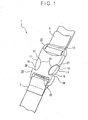
FIG. 1 is a schematic perspective view of an embodiment of buckle according to the invention; -
FIG. 2 is a perspective view of the male member and the female member of the embodiment ofFIG 1 that are released from each other; -
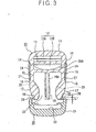
FIG. 3 is a schematic cross sectional view of the male member and the female member of the embodiment ofFIG 1 that are anchored to each other, -
FIG. 4 is a schematic cross sectional partial view of the embodiment ofFIG 1 , illustrating how the male member and the female member that have been anchored to each other are released from each other, -
FIG. 5 is a schematic cross sectional partial view of one of the apertures obtained by modifying the profile of those of the embodiment; and -
FIG. 6 is a schematic cross sectional view of a buckle obtained by modifying the embodiment - Now, the present invention will be described by referring to the accompanying drawings that schematically illustrate an illustrative embodiment of the invention.
-
FIGS. 1 through 4 illustrate this embodiment of buckle according to the invention. As shown inFIG 1 , the embodiment of buckle 1 is adapted to connect and disconnect theends male member 10 made of synthetic resin as integral entity and afemale member 20, which themale member 10 is inserted into and held, also made of synthetic resin as integral entity. Incidentally, the material used for forming themale member 10 and thefemale member 20 is not limited to synthetic resin, it can alternatively be metal or some other appropriate material. - As also shown in
FIGS. 2 and3 , themale member 10 has a male membermain body 11, a pair ofinsertion pieces 15 projecting respectively from the lateral sides of the male membermain body 11 in parallel with each other so as to be resiliently deformable, and aguide piece 19 projecting between and in parallel with theinsertion pieces 15. - The male member
main body 11 is provided at a middle section thereof with a strapfitting slot 12, through which thecorresponding end 2 of the strap member is passed and to which it is anchored, and at the lateral sides thereof with a pair of abuttingsections 14 to which the connectingsurface 20A of thefemale member 20 abuts. The strapfitting slot 12 is further divided into two strapfitting apertures link beam 13, which is interposed in the strapfitting slot 12, to regulate the effective length of the strap member. - The
insertion piece 15 is composed of a pair of thin andresilient arm sections 15A integrally formed with and extending from the lateral sides of the respective male membermain body 11 and a pair of bulgedsections 15B extending respectively from the front ends of theresilient arm sections 15A. Each of the bulgedsections 15B has aninsertion guide surface 16 that is outwardly rounded from an inner position of the base end toward the front end thereof, anoperating section 17 that is a mildly outwardly curved surface extended from the front end of theinsertion guide surface 16, and ananchor surface 18 extending inwardly from the operatingsection 17 substantially at a right or acute angle, theinsertion guide surface 16, the operatingsection 17 and theanchor surface 18 being arranged in the mentioned order. - The
guide piece 19 is formed in such a way that its thickness is gradually reduced as it extends from the male membermain body 11 toward a middle section thereof and then increased as it extends further from the middle section toward the front end thereof. A rectangularhollow section 19A is formed in theguide piece 19 from the rear surface thereof to reduce the volume of the material consumed for the buckle. - As also shown in
FIGS. 2 and3 , thefemale member 20 has a female membermain body 21. - The female member
main body 21 is provided with a strapfitting slot 22, through which thecorresponding end 3 of the strap member is inserted and to which it is anchored, and aninsertion hole 23 running all the way from the connectingsurface 20A of thefemale member 20 to be connected to themale member 10 to the strapfitting slot 22, into which theinsertion pieces 15 and theguide piece 19 of the male member are inserted. The connectingsurface 20A of the female member 20 (to be connected to the male member 10) shows an inwardly curved profile that is recessed most at the center. - The oppositely disposed lateral walls of the
insertion hole 23 extending from the inlet aperture of the latter are gradually inwardly inclined toward the remote end of the hole so that, when the insertion pieces are inserted into theinsertion hole 23, each of them operates as abuttingsection 24 that abuts theinsertion guide surface 16 of thecorresponding insertion piece 15 and resiliently deforms thepiece 15 in a direction substantially perpendicular to the inserting direction of theinsertion piece 15.Apertures 25 that expose therespective operating sections 17 of themale member 10 are formed through the lateral walls of theinsertion hole 23 in areas located beyond the respective abuttingsections 24 as viewed from theinsertion hole 23. - The
apertures 25 are produced by partly and inwardly cutting out the front andrear walls main body 21 having theinsertion hole 23 from thelateral walls 21A. To be more specific, each of theapertures 25 is produced by inwardly cutting out the front andrear walls aperture edge 25A that is located closer to theinsertion hole 23 than theother aperture edge 25B is provided with an anchor-holdingsurface 27 that comes to be engaged with theanchor surface 18 of thecorresponding insertion piece 15 to anchor themale member 10 to thefemale member 20, whereas theaperture edge 25B that is located remote from the inlet aperture of theinsertion hole 23 is provided with a projectingsection 28 that projects toward the aperture of the lateral wall. - The projecting
section 28 has a curved surface defined by lines extending from theedges 25C of the cut out parts of the front andrear walls lateral wall 21A. To be more specific, the projectingsection 28 projects toward theaperture edge 25A of the corresponding lateral wall as the defining lines are extended from theedges 25C of the cut out parts of the front andrear walls lateral wall 21A. The transversal dimension of the projectingsection 28 is large at the base section thereof (at the position indicated by the dotted broken line defining the lower end of L1 inFIG 3 ) and small at the front end section thereof (at the position indicated by the dotted broken line defining the upper end of L1 inFIG 3 ). In other words, the projectingsection 28 is tapered toward the front end thereof. - The height of the projecting section 28 (as indicated by L1 in
FIG 3 ), which is the distance L1 from the deepest position of theedges 25C of the cut out parts of the front andrear walls section 28, is so selected that the thumb or finger depressing thecorresponding operating section 17 is not caught by the gap between the projectingsection 28 and theinsertion guide surface 16 and theoperating section 17 of theinsertion piece 15. - Note that, in a state where the
male member 10 is inserted into and anchored to thefemale member 20, the outermost surface of each of the operatingsections 17 is located inside the contour line connecting the separated parts of the correspondinglateral wall 21A of the female membermain body 21. - The above described embodiment operates in a manner as described below. To anchor the
male member 10 to thefemale member 20, the user inserts theinsertion pieces 15 of themale member 10 into theinsertion hole 23 of thefemale member 20. Then, the insertion guide surfaces 16 formed at the front ends of theinsertion pieces 15 abut the respective abuttingsections 24 of thefemale member 20 so that theinsertion pieces 15 are inserted further as they are resiliently deformed in respective directions (inwardly) that are substantially perpendicular to the inserting direction of theinsertion pieces 15. As the anchor surfaces 18 of theinsertion pieces 15 pass by the respective anchor-holdingsurfaces 27 of thefemale member 20, the resilientlydeformed insertion pieces 15 restore the original state so that the anchor surfaces 18 of theinsertion pieces 15 are retained by the respective anchor-holdingsurfaces 27 of thefemale member 20. As a result, themale member 10 is anchored to thefemale member 20. - To release the
male member 10 from thefemale member 20, the user inwardly depresses the operatingsections 17 formed at the front ends of therespective insertion pieces 15 and projecting from therespective apertures 25 of thefemale member 20, and by doing so, theinsertion pieces 15 of themale member 10 are inwardly and resiliently deformed and hence the anchor surfaces 18 are released from the respective anchor-holdingsurfaces 27. In this state, the connection between themale member 10 and thefemale member 20 can be disconnected by pulling out themale member 10 from thefemale member 20. - At this time, as the operating
sections 17 of themale member 10 are depressed inwardly, the depressing thumb and finger of the user abut the projectingsections 28 so that they cannot go deep into thefemale member 20 through theapertures 25. Therefore, theinsertion pieces 15 of themale member 10 are not deformed beyond the necessary level. In other words, theinsertion pieces 15 are not damaged and broken unnecessarily so that service life thereof is prolonged. - Additionally, since the thumb and finger of the user for depressing the operating
sections 17 abut the respective projectingsections 28 and therefore cannot go deep into the female member through theapertures 25, neither the thumb nor the finger would be pinched between the operatingsections 17 of themale member 10 and the edges of the correspondingapertures 25 of thefemale member 20. If the user temporarily removes or reduces the pressure he or she is applying to the operatingsections 17 of theinsertion pieces 15 in an operation of, for example, releasing themale member 10 from thefemale member 20, theinsertion pieces 15 tend to restore the respective outer positions by resiliency. If theinsertion pieces 15 actually restore the respective outer positions by resiliency, neither the thumb nor the finger of the user that are depressing the operatingmembers 17 of themale member 10 would be pinched between the operatingsections 17 and the edges of the correspondingapertures 25 of thefemale member 20 because they do not go deep into thefemale member 20 through theapertures 25 due to the provision of the projectingsections 28. - The above described embodiment can provide the following advantages.
- (1) Since the
apertures 25 of thefemale member 20 are produced by partly and inwardly cutting out the front andrear walls main body 21 with theinsertion hole 23 formed therein, and the projectingsections 28 that project toward the apertures of the lateral walls is provided in the vicinity of the aperture edges 25B, the thumb and finger, which depress the operatingsections 17 of themale member 10 to release themale member 10 from thefemale member 20, abut the projectingsections 28 and therefore cannot go deep into thefemale member 20 through theapertures 25. In other words, theinsertion pieces 15 of themale member 10 are not deformed beyond the necessary level so that theinsertion pieces 15 are not damaged and broken unnecessarily and hence service life thereof is prolonged. - (2) Since the thumb and finger of the user for depressing the operating
sections 17 cannot go deep into the female member through theapertures 25, neither the thumb nor the finger would be pinched between the operatingsections 17 of themale member 10 and the edges of the correspondingapertures 25 of thefemale member 20. If the user temporarily removes or reduces the pressure he or she is applying to the operatingsections 17 of theinsertion pieces 15 in an operation of releasing themale member 10 from thefemale member 20, theinsertion pieces 15 tend to restore the respective outer positions by resiliency, neither the thumb nor the finger of the user that are depressing the operatingmembers 17 of themale member 10 would be pinched between the operatingsections 17 and the edges of the correspondingapertures 25 of thefemale member 20 because they do not go deep into thefemale member 20 through theapertures 25 due to the provision of the projectingsections 28. - (3) The projecting
sections 28 have a curved surface defined by lines extending from theedges 25C of the cut out parts of the front andrear walls lateral walls 21A. Therefore, when the projectingsections 28 are pushed by the thumb and one of the fingers of the user, they are not pressed intensively at a spot Additionally, since they have a curved surface, the projectingsections 28 are prevented from being damaged. - (4) The aperture edges 25A that are located closer to the
insertion hole 23 than the other aperture edges 25B are provided with respective anchor-holdingsurfaces 27, whereas the aperture edges 25B that are located remote from the inlet aperture of theinsertion hole 23 are provided with respective projectingsections 28 that project toward the apertures of the respective lateral walls. Therefore, when the user depresses the operatingsections 17 of themale member 10 by the thumb and one of the fingers to release themale member 10 from thefemale member 20, he or she uses the thumb pad and the finger pad and depresses the operatingsections 17 at positions close to the respective anchor-holdingsurfaces 27. Then, themale member 10 is released from thefemale member 20 if the operatingsections 17 are depressed only to a small extent. - (5) Since the
male member 10 is provided with a pair ofinsertion pieces 15 arranged at respective lateral extreme positions, each having ananchor surface 18 and anoperating section 17, the anchor surfaces 18 formed on the pair ofinsertion pieces 15 hold the respective anchor-holdingsurfaces 27 of thefemale member 20 when themale member 10 is fully inserted into thefemale member 20, thus themale member 10 is reliably anchored to thefemale member 20. To release themale member 10 from thefemale member 20, it is only necessary to inwardly depress the operatingsections 17 arranged on the outer lateral surfaces of the pairedinsertion pieces 15 and hence themale member 10 can be easily released from thefemale member 20. - (6) Since the
male member 10 and thefemale member 20 are made of synthetic resin as integral entities, they can be manufactured at low cost on a mass production basis. - (7) The
male member 10 and thefemale member 20 are provided respectively with the strapfitting slots male member 10 and thefemale member 20 can be easily and securely linked to the strap member simply by passing the strap member through the strapfitting slots - (8) The outermost lateral surface of each of the operating
sections 17 is located inside the contour line connecting the two separated parts of the correspondinglateral wall 21A of the female membermain body 21, in other words, the operatingsections 17 of themale member 10 are not projecting from the outer surface of the female membermain body 21, therefore, the strap or the belt would not be caught by the operatingsections 17. - While the
apertures 25 of thefemale member 20 of the above described embodiment are produced by partly and inwardly cutting out the front andrear walls apertures 25 is not limited thereto and may alternatively have a different profile. For example, they may have a rhombic profile having two linear sides that are in parallel with each other and fall inwardly and downwardly (toward the strapfitting slot 22 of the female member 20) from the aperture edges 25A, 25B of the respective lateral walls as shown inFIG 5 . With this arrangement, the projectingsections 28 are formed at the aperture edges 25B of the lateral walls simultaneously when theapertures 25 having a rhombic profile are formed. - While it is sufficient that the projecting
sections 28 have a height L1 that does not allow the thumb and one of the fingers of the user depressing the operatingsections 17 to enter the respective gaps between the projectingsections 28 and the insertion guide surfaces 16 and the operatingsections 17 of thecorresponding insertion pieces 15, it is desirable that the height L1 is determined corresponding to the distance L2 between the aperture edges 25A, 25B of each of theapertures 25 as shown inFIG. 5 . More specifically, it is desirable to select a value for the height L1 corresponding to the value for distance L2, which is set corresponding to the size of the thumb or the fingers of the user for letting the thumb and one of the fingers depressing the projectingsections 28 touch (bridge) the aperture edges 25A, 25B of the respective lateral walls. - While the insertion guide surfaces 16 are formed at the front ends of the
respective insertion pieces 15 of the above described embodiment, they may alternatively be formed at middle positions of theinsertion pieces 15 instead of the front ends. - While the anchor-holding
surfaces 27 are formed at the aperture edges 25A of the lateral walls of theapertures 25 in the above described embodiment, the positions of the anchor-holdingsurfaces 27 are not limited thereto. They may alternatively be formed at positions separated from theapertures 25. - While the above described embodiment is provided with a pair of
insertion pieces 15, it may alternatively be provided with asingle insertion piece 15 or more than twoinsertion pieces 15. -
FIG 6 shows a buckle having only asingle insertion piece 15. In the illustrated instance, therefore, only asingle aperture 25 is formed at a lateral side of thefemale member 20. With this arrangement, the advantages of (1), (2), (3), (4), (6), (7) and (8) listed above by referring to the embodiment are provided. - The above described embodiment of buckle can find numerous applications including bags. Particularly, it may find suitable applications where the buckle should not be unfastened when tensile force exceeding a predetermined level is applied thereto.
- While both the
male member 10 and thefemale member 20 of the above described embodiment are formed by molding synthetic resin (injection molding or injection/compression molding), they may alternatively be formed by molding metal and the like.
Claims (6)
- A buckle (1) comprising a male member (10) and a female member (20) for receiving and anchoring the male member ;
said male member (10) having a male member main body (11), a pair of resiliently deformable insertion pieces (15) formed on the male member main body, a pair of anchor surfaces (18) formed on the insertion pieces and a pair of operating sections (17) also formed on the insertion pieces and adapted to resiliently deform the insertion pieces ;
said female member (20) having a female member main body (21), an insertion hole (23) formed in the female member main body and adapted to receive the insertion pieces (15) of the male member (10) inserted into it, a pair of anchor-holding surfaces (27) formed on the female member main body to be engaged with the anchor surfaces (18) of said male member so as to hold the male member in the female member and a pair of apertures (25) adapted to expose the operating sections (17) of said male member to the outside as the anchor-holding surfaces are engaged with the anchor surfaces ; characterized in that
said apertures (25) are formed by inwardly cutting out the front and rear walls (21B, 21C) of the female member main body (21) having said insertion hole (23) continuously in a curved shape from edges (25A) of the lateral walls (25A) on which the anchor-holding surfaces (27) are provided, and in that said apertures (25) are provided at peripheral edges thereof with projecting sections (28) projecting toward the apertures, said projecting sections (28) being formed at edges (25B) of said apertures (25) located remotely from an inlet aperture of said insertion hole (23), said projecting sections (28) being formed to show a curved profile continuously from edges (25C) of cut out areas of the front and rear walls of the female member to the lateral walls to be continuous with the curved apertures (25), and in that outer surfaces of the operating sections (17) are exposed to the outside of the female member (20) through the apertures (25) and inner sides of the operating sections (17) opposite to the outer surfaces exposed by the apertures (25) are curved to show substantially the same curve as the apertures (25). - A buckle according to claim 1, wherein said projecting sections (28) project continuously from positions of the edges (25C) of the cut out areas of the front and rear walls, the positions being remotest from the inlet aperture of the insertion hole (23) and transversal dimensions of the projecting sections are gradually reduced toward the inlet aperture of the insertion hole (23).
- A buckle according to claim 1 or 2, wherein the state where the male member is anchored to the female member can be dissolved by depressing the operating sections (17) of the male member (10) that are exposed to the outside from the apertures (25) of the female member (20); and projecting front ends of said projecting sections (28) are located closer to the inlet aperture of the insertion hole (23) than front ends of the insertion pieces (15) anchored to the inside of the insertion hole (23).
- A buckle according to any of claims 1 through 3, wherein said male member (10) has a pair of insertion pieces (15) projecting respectively along the lateral edges of the male body main body (11) in parallel with each other and said anchor surfaces (18) and said operating sections (17) are arranged respectively on the surfaces opposite to the mutually opposing sides of the corresponding insertion pieces (15), whereas said anchor-holding surfaces (27) and said apertures (25) are formed respectively at the oppositely disposed lateral walls of the insertion hole (23) of the female member (20).
- A buckle according to any of claims 1 through 4, wherein said male member (10) and said female member (20) are made of synthetic resin as integral entities.
- A buckle according to any of claims 1 through 5, wherein said male member (10) and said female member (20) are provided respectively with strap fitting slots (12, 22), through which the corresponding ends of the strap member are passed and to which they are anchored.
Applications Claiming Priority (2)
| Application Number | Priority Date | Filing Date | Title |
|---|---|---|---|
| JP2002231993A JP3892363B2 (en) | 2002-08-08 | 2002-08-08 | buckle |
| JP2002231993 | 2002-08-08 |
Publications (2)
| Publication Number | Publication Date |
|---|---|
| EP1388301A1 EP1388301A1 (en) | 2004-02-11 |
| EP1388301B1 true EP1388301B1 (en) | 2009-01-21 |
Family
ID=30437777
Family Applications (1)
| Application Number | Title | Priority Date | Filing Date |
|---|---|---|---|
| EP03017927A Expired - Lifetime EP1388301B1 (en) | 2002-08-08 | 2003-08-06 | Buckle |
Country Status (7)
| Country | Link |
|---|---|
| US (1) | US20040025310A1 (en) |
| EP (1) | EP1388301B1 (en) |
| JP (1) | JP3892363B2 (en) |
| KR (1) | KR100737658B1 (en) |
| CN (1) | CN1248610C (en) |
| DE (1) | DE60325920D1 (en) |
| TW (1) | TW200405796A (en) |
Families Citing this family (11)
| Publication number | Priority date | Publication date | Assignee | Title |
|---|---|---|---|---|
| US7725994B2 (en) * | 2005-01-28 | 2010-06-01 | Ykk Corporation | Buckle, injection molding die and injection molding method |
| US20070089280A1 (en) * | 2005-10-24 | 2007-04-26 | Pontaoe John S | Side-release buckle assembly |
| US8256072B2 (en) * | 2006-12-12 | 2012-09-04 | Illinois Tool Works Inc. | Buckle |
| JP5651282B2 (en) * | 2007-07-03 | 2015-01-07 | Ykk株式会社 | buckle |
| JP4912251B2 (en) * | 2007-08-08 | 2012-04-11 | Ykk株式会社 | buckle |
| WO2011161802A1 (en) * | 2010-06-24 | 2011-12-29 | Ykk株式会社 | Configuration of a belt attachment part |
| CN102758572B (en) * | 2012-08-07 | 2015-08-26 | 上海鸿研物流技术有限公司 | Hinge fixing structure and concealed hinge and container |
| KR101635745B1 (en) * | 2015-01-21 | 2016-07-04 | (주)경도상사 | Fastening apparatus for shoelace |
| KR101639370B1 (en) * | 2015-01-21 | 2016-07-13 | (주)경도상사 | Easy separating operation buckle |
| JP3197854U (en) | 2015-03-25 | 2015-06-04 | Ykk株式会社 | buckle |
| KR101919760B1 (en) | 2017-02-02 | 2018-11-20 | 주식회사 우진프라스틱 | Starp Connection Part |
Family Cites Families (6)
| Publication number | Priority date | Publication date | Assignee | Title |
|---|---|---|---|---|
| US4150464A (en) | 1977-08-10 | 1979-04-24 | Illinois Tool Works Inc. | Buckle |
| US5027481A (en) | 1990-11-01 | 1991-07-02 | Illinois Tool Works | Shell buckle |
| JPH09206113A (en) * | 1995-11-30 | 1997-08-12 | Yoshio Tokuda | Guidless buckle made of plastic |
| JP3009366B2 (en) | 1997-01-30 | 2000-02-14 | 美生 徳田 | buckle |
| JP2000106915A (en) * | 1998-09-30 | 2000-04-18 | Ykk Corp | Buckle |
| JP4299941B2 (en) * | 2000-02-10 | 2009-07-22 | 株式会社ニフコ | buckle |
-
2002
- 2002-08-08 JP JP2002231993A patent/JP3892363B2/en not_active Expired - Lifetime
-
2003
- 2003-08-05 KR KR1020030053964A patent/KR100737658B1/en active IP Right Grant
- 2003-08-06 DE DE60325920T patent/DE60325920D1/en not_active Expired - Lifetime
- 2003-08-06 EP EP03017927A patent/EP1388301B1/en not_active Expired - Lifetime
- 2003-08-07 TW TW092121698A patent/TW200405796A/en unknown
- 2003-08-07 US US10/636,827 patent/US20040025310A1/en not_active Abandoned
- 2003-08-08 CN CNB031275915A patent/CN1248610C/en not_active Expired - Lifetime
Also Published As
| Publication number | Publication date |
|---|---|
| DE60325920D1 (en) | 2009-03-12 |
| US20040025310A1 (en) | 2004-02-12 |
| EP1388301A1 (en) | 2004-02-11 |
| JP3892363B2 (en) | 2007-03-14 |
| JP2004065773A (en) | 2004-03-04 |
| KR20040014269A (en) | 2004-02-14 |
| CN1248610C (en) | 2006-04-05 |
| CN1473523A (en) | 2004-02-11 |
| TW200405796A (en) | 2004-04-16 |
| KR100737658B1 (en) | 2007-07-09 |
Similar Documents
| Publication | Publication Date | Title |
|---|---|---|
| US7979966B2 (en) | Buckle | |
| US4282634A (en) | Buckle | |
| JP3394849B2 (en) | Tethers | |
| KR950003345Y1 (en) | Buckle assembly | |
| US4672725A (en) | Snap buckle | |
| US7574779B2 (en) | String holder | |
| EP1388301B1 (en) | Buckle | |
| CN102164519B (en) | Buckle | |
| US20090293243A1 (en) | Buckle | |
| TWI504356B (en) | Buckle | |
| TW200913921A (en) | Buckle | |
| US10588383B2 (en) | Buckle | |
| JP3494588B2 (en) | Side push open buckle | |
| JP4040451B2 (en) | End cover of string or band | |
| US11559113B2 (en) | Plug for buckle, and buckle | |
| JP2001218607A (en) | String stopper | |
| JP3210712U (en) | Connector | |
| JPH0724105U (en) | buckle | |
| JPH07313218A (en) | Cord stopper | |
| JPH06154012A (en) | Buckle | |
| JP2002095502A (en) | Belt connector | |
| TWI726392B (en) | buckle | |
| CN219679920U (en) | Rope fastener | |
| CN212803892U (en) | Eye-splice | |
| TWI580371B (en) | Buckle |
Legal Events
| Date | Code | Title | Description |
|---|---|---|---|
| PUAI | Public reference made under article 153(3) epc to a published international application that has entered the european phase |
Free format text: ORIGINAL CODE: 0009012 |
|
| AK | Designated contracting states |
Kind code of ref document: A1 Designated state(s): AT BE BG CH CY CZ DE DK EE ES FI FR GB GR HU IE IT LI LU MC NL PT RO SE SI SK TR |
|
| AX | Request for extension of the european patent |
Extension state: AL LT LV MK |
|
| 17P | Request for examination filed |
Effective date: 20040510 |
|
| AKX | Designation fees paid |
Designated state(s): DE ES FR GB IT |
|
| 17Q | First examination report despatched |
Effective date: 20060901 |
|
| 17Q | First examination report despatched |
Effective date: 20060901 |
|
| GRAP | Despatch of communication of intention to grant a patent |
Free format text: ORIGINAL CODE: EPIDOSNIGR1 |
|
| GRAS | Grant fee paid |
Free format text: ORIGINAL CODE: EPIDOSNIGR3 |
|
| GRAA | (expected) grant |
Free format text: ORIGINAL CODE: 0009210 |
|
| RAP1 | Party data changed (applicant data changed or rights of an application transferred) |
Owner name: YKK CORPORATION |
|
| AK | Designated contracting states |
Kind code of ref document: B1 Designated state(s): DE ES FR GB IT |
|
| REG | Reference to a national code |
Ref country code: GB Ref legal event code: FG4D |
|
| REF | Corresponds to: |
Ref document number: 60325920 Country of ref document: DE Date of ref document: 20090312 Kind code of ref document: P |
|
| PG25 | Lapsed in a contracting state [announced via postgrant information from national office to epo] |
Ref country code: ES Free format text: LAPSE BECAUSE OF FAILURE TO SUBMIT A TRANSLATION OF THE DESCRIPTION OR TO PAY THE FEE WITHIN THE PRESCRIBED TIME-LIMIT Effective date: 20090502 |
|
| PLBE | No opposition filed within time limit |
Free format text: ORIGINAL CODE: 0009261 |
|
| STAA | Information on the status of an ep patent application or granted ep patent |
Free format text: STATUS: NO OPPOSITION FILED WITHIN TIME LIMIT |
|
| 26N | No opposition filed |
Effective date: 20091022 |
|
| GBPC | Gb: european patent ceased through non-payment of renewal fee |
Effective date: 20090806 |
|
| PG25 | Lapsed in a contracting state [announced via postgrant information from national office to epo] |
Ref country code: GB Free format text: LAPSE BECAUSE OF NON-PAYMENT OF DUE FEES Effective date: 20090806 |
|
| REG | Reference to a national code |
Ref country code: FR Ref legal event code: PLFP Year of fee payment: 14 |
|
| REG | Reference to a national code |
Ref country code: FR Ref legal event code: PLFP Year of fee payment: 15 |
|
| REG | Reference to a national code |
Ref country code: FR Ref legal event code: PLFP Year of fee payment: 16 |
|
| PGFP | Annual fee paid to national office [announced via postgrant information from national office to epo] |
Ref country code: FR Payment date: 20200715 Year of fee payment: 18 |
|
| PGFP | Annual fee paid to national office [announced via postgrant information from national office to epo] |
Ref country code: IT Payment date: 20200713 Year of fee payment: 18 |
|
| PG25 | Lapsed in a contracting state [announced via postgrant information from national office to epo] |
Ref country code: IT Free format text: LAPSE BECAUSE OF NON-PAYMENT OF DUE FEES Effective date: 20210806 Ref country code: FR Free format text: LAPSE BECAUSE OF NON-PAYMENT OF DUE FEES Effective date: 20210831 |
|
| PGFP | Annual fee paid to national office [announced via postgrant information from national office to epo] |
Ref country code: DE Payment date: 20220621 Year of fee payment: 20 |
|
| REG | Reference to a national code |
Ref country code: DE Ref legal event code: R071 Ref document number: 60325920 Country of ref document: DE |