EP1387975B2 - Method and device for controlling the switching movement of a valve - Google Patents
Method and device for controlling the switching movement of a valve Download PDFInfo
- Publication number
- EP1387975B2 EP1387975B2 EP02738049A EP02738049A EP1387975B2 EP 1387975 B2 EP1387975 B2 EP 1387975B2 EP 02738049 A EP02738049 A EP 02738049A EP 02738049 A EP02738049 A EP 02738049A EP 1387975 B2 EP1387975 B2 EP 1387975B2
- Authority
- EP
- European Patent Office
- Prior art keywords
- valve
- pressure medium
- valve rod
- tolerance
- fixed position
- Prior art date
- Legal status (The legal status is an assumption and is not a legal conclusion. Google has not performed a legal analysis and makes no representation as to the accuracy of the status listed.)
- Expired - Lifetime
Links
- 238000000034 method Methods 0.000 title claims abstract description 24
- 238000009434 installation Methods 0.000 claims description 20
- 238000004891 communication Methods 0.000 claims description 13
- 238000013459 approach Methods 0.000 claims description 10
- 238000012423 maintenance Methods 0.000 claims description 6
- 239000008186 active pharmaceutical agent Substances 0.000 claims description 3
- 238000009826 distribution Methods 0.000 claims description 2
- 238000004040 coloring Methods 0.000 claims 1
- 239000006185 dispersion Substances 0.000 claims 1
- 238000001514 detection method Methods 0.000 description 10
- 230000008859 change Effects 0.000 description 8
- 238000004140 cleaning Methods 0.000 description 8
- BGPVFRJUHWVFKM-UHFFFAOYSA-N N1=C2C=CC=CC2=[N+]([O-])C1(CC1)CCC21N=C1C=CC=CC1=[N+]2[O-] Chemical group N1=C2C=CC=CC2=[N+]([O-])C1(CC1)CCC21N=C1C=CC=CC1=[N+]2[O-] BGPVFRJUHWVFKM-UHFFFAOYSA-N 0.000 description 6
- 230000001419 dependent effect Effects 0.000 description 5
- 239000002184 metal Substances 0.000 description 5
- 240000006829 Ficus sundaica Species 0.000 description 4
- 238000006073 displacement reaction Methods 0.000 description 4
- 230000006870 function Effects 0.000 description 4
- 230000006978 adaptation Effects 0.000 description 3
- 230000003750 conditioning effect Effects 0.000 description 3
- 239000012530 fluid Substances 0.000 description 3
- 238000012545 processing Methods 0.000 description 3
- 239000003637 basic solution Substances 0.000 description 2
- 230000008901 benefit Effects 0.000 description 2
- 239000003086 colorant Substances 0.000 description 2
- 239000007787 solid Substances 0.000 description 2
- 241000196324 Embryophyta Species 0.000 description 1
- 230000004913 activation Effects 0.000 description 1
- 230000032683 aging Effects 0.000 description 1
- 239000002585 base Substances 0.000 description 1
- 238000004364 calculation method Methods 0.000 description 1
- 238000006243 chemical reaction Methods 0.000 description 1
- 230000000295 complement effect Effects 0.000 description 1
- 238000007796 conventional method Methods 0.000 description 1
- 238000005520 cutting process Methods 0.000 description 1
- 238000013500 data storage Methods 0.000 description 1
- 238000013461 design Methods 0.000 description 1
- 238000011156 evaluation Methods 0.000 description 1
- 239000000284 extract Substances 0.000 description 1
- 230000007257 malfunction Effects 0.000 description 1
- 238000004519 manufacturing process Methods 0.000 description 1
- 238000012544 monitoring process Methods 0.000 description 1
- 230000003287 optical effect Effects 0.000 description 1
- 230000003252 repetitive effect Effects 0.000 description 1
- 238000007789 sealing Methods 0.000 description 1
Images


Classifications
-
- F—MECHANICAL ENGINEERING; LIGHTING; HEATING; WEAPONS; BLASTING
- F16—ENGINEERING ELEMENTS AND UNITS; GENERAL MEASURES FOR PRODUCING AND MAINTAINING EFFECTIVE FUNCTIONING OF MACHINES OR INSTALLATIONS; THERMAL INSULATION IN GENERAL
- F16K—VALVES; TAPS; COCKS; ACTUATING-FLOATS; DEVICES FOR VENTING OR AERATING
- F16K31/00—Actuating devices; Operating means; Releasing devices
- F16K31/003—Actuating devices; Operating means; Releasing devices operated without a stable intermediate position, e.g. with snap action
-
- F—MECHANICAL ENGINEERING; LIGHTING; HEATING; WEAPONS; BLASTING
- F16—ENGINEERING ELEMENTS AND UNITS; GENERAL MEASURES FOR PRODUCING AND MAINTAINING EFFECTIVE FUNCTIONING OF MACHINES OR INSTALLATIONS; THERMAL INSULATION IN GENERAL
- F16K—VALVES; TAPS; COCKS; ACTUATING-FLOATS; DEVICES FOR VENTING OR AERATING
- F16K1/00—Lift valves or globe valves, i.e. cut-off apparatus with closure members having at least a component of their opening and closing motion perpendicular to the closing faces
- F16K1/32—Details
- F16K1/34—Cutting-off parts, e.g. valve members, seats
- F16K1/44—Details of seats or valve members of double-seat valves
- F16K1/443—Details of seats or valve members of double-seat valves the seats being in series
- F16K1/446—Details of seats or valve members of double-seat valves the seats being in series with additional cleaning or venting means between the two seats
-
- F—MECHANICAL ENGINEERING; LIGHTING; HEATING; WEAPONS; BLASTING
- F16—ENGINEERING ELEMENTS AND UNITS; GENERAL MEASURES FOR PRODUCING AND MAINTAINING EFFECTIVE FUNCTIONING OF MACHINES OR INSTALLATIONS; THERMAL INSULATION IN GENERAL
- F16K—VALVES; TAPS; COCKS; ACTUATING-FLOATS; DEVICES FOR VENTING OR AERATING
- F16K31/00—Actuating devices; Operating means; Releasing devices
- F16K31/12—Actuating devices; Operating means; Releasing devices actuated by fluid
- F16K31/122—Actuating devices; Operating means; Releasing devices actuated by fluid the fluid acting on a piston
- F16K31/1225—Actuating devices; Operating means; Releasing devices actuated by fluid the fluid acting on a piston with a plurality of pistons
-
- F—MECHANICAL ENGINEERING; LIGHTING; HEATING; WEAPONS; BLASTING
- F16—ENGINEERING ELEMENTS AND UNITS; GENERAL MEASURES FOR PRODUCING AND MAINTAINING EFFECTIVE FUNCTIONING OF MACHINES OR INSTALLATIONS; THERMAL INSULATION IN GENERAL
- F16K—VALVES; TAPS; COCKS; ACTUATING-FLOATS; DEVICES FOR VENTING OR AERATING
- F16K37/00—Special means in or on valves or other cut-off apparatus for indicating or recording operation thereof, or for enabling an alarm to be given
- F16K37/0025—Electrical or magnetic means
- F16K37/0033—Electrical or magnetic means using a permanent magnet, e.g. in combination with a reed relays
-
- F—MECHANICAL ENGINEERING; LIGHTING; HEATING; WEAPONS; BLASTING
- F16—ENGINEERING ELEMENTS AND UNITS; GENERAL MEASURES FOR PRODUCING AND MAINTAINING EFFECTIVE FUNCTIONING OF MACHINES OR INSTALLATIONS; THERMAL INSULATION IN GENERAL
- F16K—VALVES; TAPS; COCKS; ACTUATING-FLOATS; DEVICES FOR VENTING OR AERATING
- F16K37/00—Special means in or on valves or other cut-off apparatus for indicating or recording operation thereof, or for enabling an alarm to be given
- F16K37/0075—For recording or indicating the functioning of a valve in combination with test equipment
- F16K37/0083—For recording or indicating the functioning of a valve in combination with test equipment by measuring valve parameters
-
- Y—GENERAL TAGGING OF NEW TECHNOLOGICAL DEVELOPMENTS; GENERAL TAGGING OF CROSS-SECTIONAL TECHNOLOGIES SPANNING OVER SEVERAL SECTIONS OF THE IPC; TECHNICAL SUBJECTS COVERED BY FORMER USPC CROSS-REFERENCE ART COLLECTIONS [XRACs] AND DIGESTS
- Y10—TECHNICAL SUBJECTS COVERED BY FORMER USPC
- Y10T—TECHNICAL SUBJECTS COVERED BY FORMER US CLASSIFICATION
- Y10T137/00—Fluid handling
- Y10T137/8158—With indicator, register, recorder, alarm or inspection means
- Y10T137/8225—Position or extent of motion indicator
- Y10T137/8242—Electrical
-
- Y—GENERAL TAGGING OF NEW TECHNOLOGICAL DEVELOPMENTS; GENERAL TAGGING OF CROSS-SECTIONAL TECHNOLOGIES SPANNING OVER SEVERAL SECTIONS OF THE IPC; TECHNICAL SUBJECTS COVERED BY FORMER USPC CROSS-REFERENCE ART COLLECTIONS [XRACs] AND DIGESTS
- Y10—TECHNICAL SUBJECTS COVERED BY FORMER USPC
- Y10T—TECHNICAL SUBJECTS COVERED BY FORMER US CLASSIFICATION
- Y10T137/00—Fluid handling
- Y10T137/8158—With indicator, register, recorder, alarm or inspection means
- Y10T137/8225—Position or extent of motion indicator
- Y10T137/8275—Indicator element rigidly carried by the movable element whose position is indicated
-
- Y—GENERAL TAGGING OF NEW TECHNOLOGICAL DEVELOPMENTS; GENERAL TAGGING OF CROSS-SECTIONAL TECHNOLOGIES SPANNING OVER SEVERAL SECTIONS OF THE IPC; TECHNICAL SUBJECTS COVERED BY FORMER USPC CROSS-REFERENCE ART COLLECTIONS [XRACs] AND DIGESTS
- Y10—TECHNICAL SUBJECTS COVERED BY FORMER USPC
- Y10T—TECHNICAL SUBJECTS COVERED BY FORMER US CLASSIFICATION
- Y10T137/00—Fluid handling
- Y10T137/8593—Systems
- Y10T137/87917—Flow path with serial valves and/or closures
- Y10T137/88038—One valve head carries other valve head
Definitions
- the invention relates to a method for controlling the switching movement of a valve according to the preamble of claim 1 and to an apparatus for carrying out the method according to the preamble of claim 9.
- valve control of this type With a known valve control of this type, the position of valve plates, for example, with an accuracy of 0.1 mm can be detected (Journal dei 1-2 / 2001, page 14 ). Precondition for this accuracy is a sensor system that allows four different detection positions.
- a device for controlling a valve in which a rectilinear position indicator detects the respective position of the valve rod and transmitted to a data register.
- the latter is associated with a control unit, which in turn has access to a solenoid valve which engages in a supply line for compressed air to the drive cylinder of the valve.
- the valve rod is connected to the closing member of the associated valve, so that the position of the valve can be detected.
- This known device performs the monitoring of the valve movement between a number of fixed valve positions.
- means are provided for storing these desired valve positions in a data memory.
- the device has control devices for comparing the current position indicators of the position indicator with the fixed switching positions of the valve, which are stored in the said data memory.
- the controller has programs in which the changes in the position indicators for the fixed valve positions are stored during the repeated valve circuits, the programs compensate for those changes that lie within a tolerance range of the stored position indicator.
- Such an arrangement has the advantage that the position indicator can adjust itself within the specified tolerance range, so that, for example, influences on the stroke of the valve due to temperature change, seal wear or change the direction of flow of the closing member, which may for example lead to a changed closed position of the valve disk , can be detected and compensated (so-called self-adjustment).
- the closing and the open position of the valve are each detected by an associated stationary position indicator. If, for example, the closing position of the valve disk and thus also the information associated with the original closed position changes as a result of the aforementioned influencing factors, then the stationarily arranged position detector can not recognize such a change.
- the position indicator is a so-called microswitch corresponding to an annular groove within the valve stem, then the groove actuating this microswitch will give a trigger signal in the original closed position, although the valve is not fully closed, for example, due to seal wear.
- a sensor system that works on the one hand with a non-contact position indicator and on the other hand can adapt to changing operating conditions of the valve within predefined tolerance ranges is referred to in relevant journals as a so-called "floating measuring system” (see periodical CIT / plus 4/01 , pages 42 to 46; Zeitschrift dei 1-2 / 2001 , page 14; Brauwelt magazine No. 46147 (2000), pages 2018 to 2023).
- valve control described in the cited references cited above, four different detection positions of the valve (fixed valve positions) mentioned there are possible.
- the two recognition positions for the closing and the open position of the valve are now also those positions to recognize, in which the valve seat is opened gap-wide over one or the other valve disc for the purpose of so-called seat cleaning, if it is in the valve to be controlled is a so-called double-seat valve, which has two relatively movable closing members, namely an independently driven valve disc and a forcibly driven by this and thus dependent so-called.
- a prerequisite for the realization of a so-called floating measuring system is a reliable non-contact, preferably rectilinear position indicator.
- a device is for example from the WO 96/10731 known.
- the device designated there as a position detection device is used to determine a position of an element, wherein in application to a valve control of the aforementioned Type of this element is a valve stem with a longitudinal axis and this is movable along its longitudinal axis.
- a magnet is attached to the element.
- an array of multiple magnetic field transducers arranged in parallel and adjacent to the path defined by the valve lifter in a straight line arrangement, each of these preferably magnetoresistive field transducers providing a bipolar output signal as the magnet approaches, passes, and from each Field converter moved away.
- the arrangement of field transducers provides a plurality of output signal values for a position of the magnet used to determine this position and thus the valve stem to which the valve stem is attached.
- the magnetic field transformers are, for example, Hall sensors that generate a change in voltage proportional to this change when the magnetic field changes.
- the provided grades i take into account the different valve types and their operating and working conditions. The selection of the quality grade i in question takes place before the first switching movement of the valve and in advance to the execution of the set-up.
- the proposed method eliminates compensation for detected changes in the fixed valve positions.
- a current fixed position message y 1 * , y 2 * , y 3 * , y 4 * assigned to the current end positions and / or the current intermediate positions is / are only used, and with the two limit values y 1o , y 1u ; y 2o , y 2u ; ... of the relevant tolerance range ⁇ T 1i , ⁇ T 2i , ... compared. From the calculation of the limits and the comparison of these limits with the current fixed position reports can be determined in a simple manner, whether the current fixed valve position is within or outside the specified tolerance range.
- an embodiment of the method provides that the fixed position reports y 1 , y 2 , y 3 , y 4 is assigned a tolerance range group. This means that each of these fixed slope messages is combined with a tolerance range of equal quality i.
- Another proposal in this context provides that the fixed position reports y 1 , y 2 , y 3 , y 4 each tolerance ranges of different grades are assigned. It follows, for example, that the closed position of the valve is associated with a narrower sized tolerance range than, for example, the less critical open position of the valve.
- the tolerance range ⁇ T 1i , ⁇ T 2i , ⁇ T 3i , ⁇ T 4i is arranged symmetrically to the assigned fixed position signal y 1 , y 2 , y 3 , y 4 .
- the proposed device for carrying out the method is characterized on the one hand by the already mentioned procedurally mentioned fixed position limits A1 to A4, which are designed as metallic stops, and by a non-contact position indicator device position indicator and by a control head facing away from the valve Side of the valve drive is arranged and receives all necessary to control the valve means.
- the position indicator designed as an electronic subassembly sensor unit in which a number of stationary, magnetoresistive field transducers are arranged in a row parallel and adjacent to a valve stem movement to be detected, wherein a magnet, connected to the valve rod, along the field transducer slidably is.
- a sensor unit is from the WO 96/10731 known.
- the position indicator consists of a further objective unit, the so-called communication unit. Sensor and communication unit are connected to each other via two interfaces.
- the sensor unit has plug connections for the pilot valves.
- the communication unit is plugged into the sensor unit and includes a microprocessor, a data memory, an internal control and display panel, a signal conditioning and all the electronics and software required for communication with a programmable logic controller, indicator lights and a screw terminal block.
- the sensor unit is the same for all valve types which can be equipped with a control head according to the invention, wherein the communication unit determines whether the position indicator as a whole is ac, dc or bus compatible.
- the proposed device is structurally simple in that, as a further proposal provides, in the control head an installation block is provided which receives the entire distribution system for the pressure medium and the pilot valves for controlling the pressure medium and the sensor and the communication unit carries existing position indicator.
- a further embodiment provides that the installation block for the highest expansion stage (maximum equipment) of the control of a valve and thus is designed for a valve with all optionally possible equipment variants. This means that all channels for the supply and the corresponding discharge of pressure medium (control air) and other connection channels are arranged in this installation block.
- the installation block for the connection of three pilot valves is equipped, so that in addition to the control of the full stroke by a first pilot valve two more pilot valves for the realization of the two intermediate positions (first and second Lifthub) can be arranged.
- the controller is equipped in such a way that different supply voltages (DC or AC voltage of different sizes) can be supplied to the controller without this particular situation leading to an exchange of the pitot valve or the pilot valves.
- the voltage conversion and adaptation to the determined by the pilot valve voltage used is carried out automatically in an advantageous manner.
- the pressure medium for controlling the valve drive for generating the full stroke is supplied to the valve drive from the outside via a first pressure medium connection.
- the above-mentioned external first pressure medium connection can be omitted if the pressure medium, as is provided by a further proposal, is guided over a valve rod bore in the valve rod.
- This valve rod bore opens at the end of the valve rod, where the magnet of the position indicator is disposed in a closed to the environment chamber chamber, which is acted upon by the pressure medium for the valve drive.
- a further embodiment of the proposed device provides that the position indicator is equipped with more than one indicator of different colors, the indicator lights are all around (360 degrees) visible via a scattered light lens, which is arranged in the closed end of a control head occlusive cover, so that the respective function of the valve can be perceived from all sides.
- the indicator By means of the indicator, the different switching states (closed position, open position, seat cleaning position), error messages, maintenance need, valve malfunctions or setup functions (set-up) are displayed.
- These indicator lights preferably three indicator lights, for example, the color green, yellow, red, the permanent or flashing lights are arranged at the head of the communication unit.
- valve drive has a fourth pressure medium connection, via which, in the closed position of the valve, the closing force on the valve rod is increased by supplying pressure medium.
- the control of this fourth pressure medium connection via a so-called NOT element, which is arranged on the installation block and with the in case of need, if the drive piston for the full stroke is not controlled, pressure medium optionally on the rear side of the drive piston for the full stroke to support the there acting spring force can be passed.
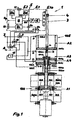
- the device according to the invention is in FIG. 1 shown applied to a valve 100, which is designed as a so-called.
- Double-seat valve and which receives a valve plate 101 and a double plate 102 between a first and a second valve housing 100a and 100b.
- the valve disk 101 experiences its independent drive via a valve rod 101a, and it comes in its opening movement of double plate 102 to the plant and transferred this also in the open position.
- the valve disk 101 cooperates with the first seat surface 103 via a first seat seal 107, and a second seat surface 104 is associated with the double disk 102 equipped with a second seat seal 108.
- Both closing members 101,102 control an unspecified connection bore between the first and second valve housings 100a and 100b.
- the valve disk 101 has a first fixed valve position y 1 (FIG. FIG. 2 ), the closed position shown, and a second fixed valve position y 2 , the open position. Between these two fixed valve positions, the end positions, a so-called full stroke H of the valve disk 101 is formed. To realize this full stroke H, a main piston 105a connected to the valve disk 101 via the valve rod 101a is acted upon by pressure medium D via a first pressure medium connection 106a either from the outside or via a valve rod bore 3b from the inside. For dependent execution of the full stroke H of the double plate 102 is dependent on the entrainment by the valve plate 101. In this context, its designed as a hollow rod 102 a valve rod has only guiding function.
- the defined end position limitation of the valve disk 101 and the double disk 102 in the respective closed position takes place via a metal bearing on the respectively assigned seat surface 103 or 104, ie the latter form the fixed position limitation A1 (first metal stop).
- the open position of the valve disk 101 and thus also of the double disk 102, the second end position, which supplies the second solid position signal y 2 , for example, as in FIG. 1 is shown schematically, realized by conditioning the main piston 105a at a second position limit A2 (second metal stop).
- the valve disk 101 is transferred to a partial open position for the purpose of its seat cleaning.
- This Teitoffengnagnagnagnagnagnagnagnagnagnagnagnagnagnagnagan or intermediate position provides the third fixed position message y 3 .
- the unique end position limit for this intermediate position is found by the first lift piston 105b at a third fixed position limit A3, the entrainment of the valve rod 101a by the first lift piston 105b via a first driver 101b formed on the valve rod 101a (third metallic stop).
- a second pressure medium connection 106b is used for pressurizing the first lift piston 105b.
- the double plate 102 can be converted into a partially open position and thus an intermediate position in which its seat cleaning is possible.
- the second lift piston 105c is acted upon by pressure medium D via a third pressure medium connection 106c.
- This intermediate position which provides the fourth fixed position message y 4 , is limited by the fourth position limit A4 (fourth metallic stop).
- the possible switching movements of the double-seat valve described above represent the maximum possible range of motion that the control according to the invention has to cope with.
- it is further provided to press the valve disk 101 in the non-activated state by means of an additional force on its seat surface 103.
- pressure medium D is applied to the main piston 105a on the rear side via a fourth pressure medium connection 106d.
- a first pilot valve 9, a second pilot valve 10 and a third pilot valve 11 are provided for feeding the pressure medium connections 106a to 106c.
- the activation of the fourth pressure medium connection 106d takes place via a so-called NOT element 15, which in case of need and whenever there is no actuation of the main piston 105a via the first pressure medium connection 106a, experiences a control.
- the control according to the invention is shown schematically, the task of which is, inter alia, to control the aforementioned pilot valves 9, 10 and 11, so that the above-described switching movements of the double-seat valve can be carried out.
- Z is the pressure medium supply
- A is the pressure medium discharge referred to.
- the valve rod 101a leading to the valve plate 101 continues above the main piston 105a in a valve rod 3, which is guided into a control head 1 and carries a magnet 4 at its end.
- the control head 1 includes i.a. a position indicator 5, which in turn consists of a sensor unit 5.1 and a communication unit 5.2.
- a position indicator 5 which in turn consists of a sensor unit 5.1 and a communication unit 5.2.
- a number of stationary magnetic field transducers 5.1a preferably magnetoresistive field transducers
- the magnetic field transducers 5.1a are so-called Hall sensors which provide a bipolar output signal as the magnet 4 approaches, passes and moves away from each magnetic field transducer 5.1a.
- the evaluation of the magnetic field passing through the magnetic field 5.1 a magnetic field for the purpose of detecting the position of the valve rod 3 is for example in the WO 96/10731 described.
- the output signals of the magnetic field converters 5.1a can be obtained serially or in parallel.
- the magnetic field converters 5.1a may be wired to a multiplexer 6, whereby the data is to be obtained serially. They are fed to an A / D converter 7, which is connected via a microprocessor 8 to a data memory 8a.
- Microprocessor 8 and data memory 8a and an internal control and display panel 8b, a signal adaptation 8c, a terminal block 8f and a connection for a parameterization device 8g are located in the communication unit 5.2, which has a first interface 8d and a second interface 8e with the sensor unit 5.1 connected is.
- a connection 8 h for the pilot valves 9, 10 and 11 is ensured via the second interface 8 e.
- control of the first switching movement of the double seat valve will allocate 100 the fixed position limits respectively approached A1 to A4, and each resulting solid position signals y 1 to y 4, measured by the information contained in the sensor unit 5.1 displacement measuring device 4, 5.1a are stored in the data memory 8a.
- These fixed position reports y 1 to y 4 are respectively assigned a tolerance range ⁇ T 1i to ⁇ T 4i specified in the data memory 8a in a predefined data set DS and from this the microprocessor 8 calculates the two limit values y 1o , y 1u to y 4o , y 4u of the respective tolerance range ⁇ T 1i to ⁇ T 4i .
- the current end positions and possibly also the current intermediate position of the valve rod 3 and the hollow rod 102a are continuously measured and the respectively assigned current fixed position signal y 1 * to y 4 * is used and with the two limit values y 1o , y 1u to y 4o , y 4u of the candidate tolerance range .DELTA.T 1i to .DELTA.T 4i compared.
- the hollow rod 102a of the double plate 102 is not guided into the control head 1 and thus in the range of the displacement measuring device 4, 5.1a, so that the intermediate position y 4 of the hollow rod 102a is not detected there can be.
- this insectsteliung is detected by a sensor, not shown, which is disposed between the second valve housing 100 b and the valve drive 105.
- the above-described fixed position reports y 1 to y 4 obtained by the position messages y generally supplied by means of the displacement measuring device 4, 5.1a, are in conjunction with the predetermined tolerance ranges ⁇ T 1i to ⁇ T 4i assigned to them FIG. 2 pictured.
- the example of the open position y 2 of the double-seat valve 100 is in FIG. 2 illustrated how the control according to the invention monitors the end positions and thus mutatis mutandis, the intermediate positions.
- the current open position y 2 for example, the current fixed position message y 2 * is determined and this measured value, based on a reference system B, is compared with the relevant limit values y 2o and y 2u .
- the measured value y 2 * is within the tolerance range ⁇ T 21 , but outside an approach tolerance ⁇ t w placed on both sides in this tolerance range, the double-seat valve 100 has reached a proper open position. This can be done, for example, by an optical signal via one of the control head 1 arranged indicator 12 (s. FIG.
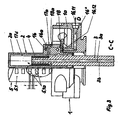
- the device for controlling the switching movement of a valve comprises in the control head 1, the outside of a housing lower part 1a ( FIG. 3 ) and this closing, not shown cover 21 is formed (s. FIG. 5 On the latter, a pot-shaped chamber housing 2a is arranged such that the end of the valve rod 3 in this, bounded on all sides and hermetically delimited from the environment, arrangement is found.
- the field of the magnet 4 spreads spatially, axially symmetric to the longitudinal axis 3a, wherein the direction given by the two poles N, S of the magnetic dipole is oriented concentrically to the longitudinal axis 3a.
- the valve rod 3 is connected to the in FIG. 3 not shown valve plate 101 (see FIG. 1 ), which changes the flow through the valve 100, and is movable along its longitudinal axis 3a.
- the pressure medium D for controlling the valve drive 105 (s. FIG. 1 ) for generating the full stroke H of the valve 100 is supplied via the valve rod bore 3b, which is executed within the valve rod 3 and terminates at the end thereof.
- the pressure medium D arrives in the valve rod bore 3b on the way from a supply port 16.11 on the housing lower part 1a via a second supply channel system 16 * in the housing lower part 1a, a supply channel connection point 16.12, a first supply channel section 16a of a supply channel system 16 in the installation block 2 , this in FIG. 3 not shown first pilot valve 9 (eg, electromagnetically operable valve; s FIG.
- the three pilot valves 9, 10 and 11 are arranged, wherein the first pilot valve 9, the full stroke H of the valve 100, the second pilot valve 10 a first partial stroke (first Lifthub for seat cleaning of the first seat 103 of the valve 100, if this is designed as a double-seat valve ) and the third pilot valve 11 a second partial lift (second Lifthub for seat cleaning of the second seat 104 of the aforementioned double-seat valve 100) controls.
- the three pilot valves 9 to 11 is located on the installation block 2, the so-called.
- NOT element 15 which is responsible for the control of the pressure medium D to the rearward loading of the main piston 105 a.
- the rearward application serves to generate an additional force, which ensures an increased closing force of the valve 100.
- a first group of pressure medium connections 13.1 which consists of three connections, is shown in each case, of which the supply connection 16.11 in FIG. 3 already mentioned.
- the second port is a discharge port 18.12, in which the aforementioned discharge channel system 18, which continues within an associated, not shown discharge channel system in the housing lower part 1a, ends.
- a check valve port 20 forms the third port.
- a first and a second terminal for control and signal processing lines 14.1 and 14.2 are provided (including supply voltage, pilot valve signals, feedback signals, external sensors).
- About the first group pressure fluid connections 13.1 the installation block 2 is connected to the outside of the control head 1 zoomed pressure medium lines.
- a connecting element 22 establishes a connection between the control head 1 and the valve drive 105 underneath.
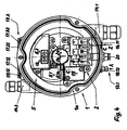
- the sensor unit 5.1 has at its upper end a dovetail-shaped fastening groove 5.1b (FIG. FIG. 4 ), in which a complementary fastening part 2 b engages at the upper end of the chamber housing 2 a for the purpose of a positive fastening.
- the communication unit 5.2 is in turn attached to the sensor unit 5.1; Together, both form the position indicator 5.
- three indicator lights 12 are provided, via which an integrated in the cover 21 scattering lens 2 a is arranged.
- the indicator 12 have different colors (for example, red, green and yellow), they can be steady or flashing light send out and their arrangement is made in cooperation with the scattered light lens 21a so that all the lights 12 are recognizable in the vicinity of the control head 1 from all directions.
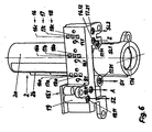
- first pressure medium channel connection 17.12 Via a first pressure medium channel connection 17.12, the first lift piston 105b (FIG. FIG. 1 ) for generating the first partial stroke (first Lifthub) pressure medium D supplied.
- a second pressure medium channel port 17.22 supplies the second lift piston 105c for generating the second partial stroke (second Lifthub) also with pressure medium D.
- Via a third pressure medium channel port 17.32 can alternatively in the FIGS. 1 and 3 described internal supply of the pressure medium D on the way via the valve rod 3 to the main piston 105 a, this external supply, that is, the main piston 105 a is one of the vorg. third pressure medium connection 17.32 outgoing hose from the outside (first pressure medium connection 106a) supplied with pressure medium D.
- a fourth pressure medium connection 19.12 controlled by the NOT element 15, pressure medium D is directed to the rear side of the main piston 105a.
- connection of the pilot valves 9 to 11 corresponding connections 9.1, 10.1 and 11.1 are respectively provided on the installation block 2 ( FIG. 6 ).
- first supply channel section 16a and a second supply channel section 16b and a third supply channel section 16c of the supply channel system 16 (FIG. FIG. 3 ).
- first pressure medium duct section 17a of a pressure medium system not shown, in the lower housing part 1a leads on the way via the fourth pressure medium duct section 17d into the interior of the chamber housing 2a (see FIG. FIG. 3 ).
- a second pressure medium channel section 17b extends from the second connection 10.1 via the installation block 2 into the valve drive 105 for controlling the first lift stroke.
- a third pressure medium passage section 17c extends from the third port 11.1 into the associated valve drive 105 for the second lift stroke.
- the first discharge channel section 18a (see also FIG. 3 ) terminates in the first port 9.1.
- a second and a third discharge channel section 18b, 18c respectively lead to the second and third connection 10.1, 11.1.
- the NOT element 15 is located on a fourth connection 15.1 (FIG. FIG. 6 ) are arranged on the installation block 2.
- the fourth pressure medium channel section 17d (s. FIG. 3 ) and thus the interior of the chamber housing 2a are connected via a not shown further pressure medium channel section with the NOT element 15.
- a arranged in the installation block 2, but not shown channel system for additional pressure medium D supplies, starting from the aforementioned fourth port 15.1 of the NOT element 15, the back of the main piston 105 for the full stroke H of the valve 100 with a corresponding pressure medium. The latter is supplied to the NOT element 15 via the supply channel system 16.
- the feed channel system 16 within the installation block 2 is located at the in FIG. 3 already shown supply channel connection point 16.12 (pressure medium supply Z) with the associated second supply channel system 16 * in the lower housing part 1a by means of a sealing ring, not shown sealingly connected ( FIG. 6 ).
- a first pressure medium channel system 17 in the installation block 2 via a first pressure medium connection point 17.11 (pressure means for first Lifthub SL1) or a second pressure medium connection point 17.21 (pressure means for the second Lifthub SL2) or a third pressure medium connection point 17.31 (external Control of the valve drive 105 for the full stroke H with the pressure medium SV) with the associated, not shown, the pressure medium channel system in the lower housing part 1a sealingly connected.
- discharge channel system 18 via a discharge channel connection point 18.11 (pressure medium discharge A) and a not shown second pressure medium channel system 19 for additional pressure medium via a fourth pressure medium connection point 19.11 (pressure means for additional load SZ) with the corresponding systems in Housing base 1a each sealingly connected.
Abstract
Description
Die Erfindung betrifft ein Verfahren zur Steuerung der Schaltbewegung eines Ventils nach dem Oberbegriff des Anspruchs 1 sowie eine Vorrichtung zur Durchführung des Verfahrens nach dem Oberbegriff des Anspruchs 9.The invention relates to a method for controlling the switching movement of a valve according to the preamble of
Mit einer bekannten Ventilsteuerung dieser Art kann die Position von Ventiltellern beispielsweise mit einer Genauigkeit von 0,1 mm erfasst werden (Zeitschrift dei 1-2/2001, Seite 14). Voraussetzung für diese Genauigkeit ist ein Sensorsystem, das vier unterschiedliche Erkennungspositionen ermöglicht.With a known valve control of this type, the position of valve plates, for example, with an accuracy of 0.1 mm can be detected (Journal dei 1-2 / 2001, page 14 ). Precondition for this accuracy is a sensor system that allows four different detection positions.
In der
Eine derartige Anordnung hat den Vorteil, dass sich die Positionsanzeige im Rahmen des vorgegebenen Toleranzbereichs selbst justieren kann, so dass beispielsweise Einflüsse auf den Hub des Ventils infolge Temperaturänderung, Dichtungsverschleiß oder Änderung der Anströmrichtung des Schließgliedes, die beispielsweise zu einer veränderten Schließlage des Ventiltellers führen können, erkannt und kompensiert werden können (sog. Selbstjustierung).Such an arrangement has the advantage that the position indicator can adjust itself within the specified tolerance range, so that, for example, influences on the stroke of the valve due to temperature change, seal wear or change the direction of flow of the closing member, which may for example lead to a changed closed position of the valve disk , can be detected and compensated (so-called self-adjustment).
Bei der herkömmlichen Technik werden beispielsweise die Schließ- und die Offenstellung des Ventils jeweils durch einen zugeordneten ortsfesten Stellungsmelder erfasst. Verändert sich nun beispielsweise durch die vorgenannten Einflussfaktoren die Schließlage des Ventiltellers und damit auch die der ursprünglichen Schließstellung zugeordnete Information, dann kann der ortsfest angeordnete Stellungsmelder eine derartige Veränderung nicht erkennen. Handelt es sich beispielsweise bei dem Stellungsmelder um einen sogenannten Mikroschalter, der mit einer ringförmigen Nut innerhalb der Ventilstange korrespondiert, dann wird die diesen Mikroschalter auslösende Nut in der ursprünglichen Schließlage ein Auslösesignal geben, obwohl das Ventil beispielsweise aufgrund eines Dichtungsverschleisses noch nicht vollständig geschlossen ist.In the conventional technique, for example, the closing and the open position of the valve are each detected by an associated stationary position indicator. If, for example, the closing position of the valve disk and thus also the information associated with the original closed position changes as a result of the aforementioned influencing factors, then the stationarily arranged position detector can not recognize such a change. For example, if the position indicator is a so-called microswitch corresponding to an annular groove within the valve stem, then the groove actuating this microswitch will give a trigger signal in the original closed position, although the valve is not fully closed, for example, due to seal wear.
Mit der in der
Ein Sensorsystem, das einerseits mit einem berührungsfrei arbeitenden Positionsanzeiger arbeitet und das andererseits sich an verändernde Betriebsbedingungen des Ventils im Rahmen vordefinierter Toleranzbereiche anpassen kann, wird in einschlägigen Fachzeitschriften als sog. "schwebendes Messsystem" bezeichnet (vergleiche Zeitschrift CIT/plus 4/01, Seiten 42 bis 46; Zeitschrift dei 1-2/2001, Seite 14; Zeitschrift Brauwelt Nr. 46147 (2000), Seiten 2018 bis 2023).A sensor system that works on the one hand with a non-contact position indicator and on the other hand can adapt to changing operating conditions of the valve within predefined tolerance ranges is referred to in relevant journals as a so-called "floating measuring system" (see periodical CIT / plus 4/01 , pages 42 to 46; Zeitschrift dei 1-2 / 2001 , page 14; Brauwelt magazine No. 46147 (2000), pages 2018 to 2023).
Mit der an den vorgenannten zitierten Literaturstellen beschriebenen Ventilsteuerung sind vier dort erwähnte unterschiedliche Erkennungspositionen des Ventils (feste Ventilstellungen) möglich. Neben den beiden Erkennungspositionen für die Schließ- und die Offenstellung des Ventils sind nun auch jene Positionen zu erkennen, in denen der Ventilsitz spaltweit über den einen oder den anderen Ventilteller zum Zwecke der sogenannten Sitzreinigung geöffnet wird, falls es sich bei dem zu steuernden Ventil um ein sogenanntes Doppelsitzventil handelt, das zwei relativ zueinander bewegliche Schließglieder aufweist, nämlich einen unabhängig angetriebenen Ventilteller und einen von diesem zwangsläufig und damit abhängig angetriebenen sog. Doppelteller.With the valve control described in the cited references cited above, four different detection positions of the valve (fixed valve positions) mentioned there are possible. In addition to the two recognition positions for the closing and the open position of the valve are now also those positions to recognize, in which the valve seat is opened gap-wide over one or the other valve disc for the purpose of so-called seat cleaning, if it is in the valve to be controlled is a so-called double-seat valve, which has two relatively movable closing members, namely an independently driven valve disc and a forcibly driven by this and thus dependent so-called.
Voraussetzung für die Realisierung eines sogenannten schwebenden Messsystems ist eine zuverlässig berührungsfrei, vorzugsweise geradlinig arbeitende Positionsanzeigevorrichtung. Eine derartige Vorrichtung ist beispielsweise aus der
Bei der Vorrichtung zur Steuerung der Ventilbewegung zwischen einer Anzahl von festen Ventilstellungen gemäß
Vorrichtungen dieser Art sind bereits aus den Dokumenten
Ausgehend von der grundlegenden Lösung einerseits zur Ventilsteuerung gemäß
Diese Aufgabe wird durch ein Verfahren mit den Merkmalen des Anspruchs 1 gelöst. Vorteilhafte Ausgestaltungen des vorgeschlagenen Verfahrens sind Gegenstand der Unteransprüche. Eine Vorrichtung zur Durchführung des Verfahrens ist gekennzeichnet durch die Merkmale des Anspruchs 9. Vorteilhafte Ausführungsformen der vorgeschlagenen Vorrichtung sind Gegenstand der nachgeordneten Unteransprüche.This object is achieved by a method having the features of
Der entscheidende Ansatz zur Erhöhung der Sicherheit bei der Erkennung der definierten festen Ventilstellungen besteht darin, dass diese Stellungen durch unmittelbare oder mittelbare Anlage der Ventilstange bzw. Ventilstangen an festen Stellungsbegrenzungen eindeutig bestimmt sind. Diese festen Stellungsbegrenzungen sind als metallische Anschläge ausgebildet. Dies bedeutet, dass sowohl in der Schließstellung des Ventils als auch in den anderen ausgezeichneten festen Ventilstellungen das unabhängig angetriebene Schließglied, der Ventilteller, eine metallische Anlage an der zugeordneten Stellungsbegrenzung (metallischer Anschlag) findet. Bei Vorrichtungen nach dem Stand der Technik ist dies beispielsweise nicht der Fall, da hier zumindest die Endlagenbegrenzung des Ventiltellers in der Schließstellung durch Auflage der mehr oder weniger duktilen, im Ventilteller angeordneten Sitzdichtung auf der zugeordneten Sitzfläche bestimmt wird. Auftretender Dichtungsverschleiß und Alterungsvorgänge verändern damit zwangsläufig die Schließstellung des Ventiltellers und erfordern bei Steuerungen nach dem Stand der Technik eine Selbstjustierung zumindest in dieser Erkennungsposition.The crucial approach to increase the safety in the detection of the defined fixed valve positions is that these positions are determined by direct or indirect investment of the valve rod or valve rods at fixed position limits. These fixed position limits are designed as metallic stops. This means that, both in the closed position of the valve and in the other excellent fixed valve positions, the independently driven closure member, the valve plate, will find a metallic abutment at the associated positional limit (metallic stop). In the case of devices according to the prior art, this is not the case, for example, since at least the end position limitation of the valve disk in the closed position is determined by the more or less ductile seat seal arranged in the valve disk on the assigned seat surface. Occurring seal wear and aging processes thus inevitably change the closed position of the valve disk and require in controls according to the prior art, a self-adjustment at least in this detection position.
Das Einrichten der Steuerung im Zuge der erstmaligen Schaltbewegungen des Ventils wird durch die festen Stellungsbegrenzungen erleichtert, da diese jeweils angefahren und die hieraus jeweils resultierenden festen Stellungsmeldungen gespeichert werden. Im Zuge dieses sog. Set-up wird der Steuerung im Vorwege die Ausstattung des Ventils mitgeteilt. Aus dieser Ausstattung resultieren die möglichen festen Ventilstellungen. Dies bedeutet, dass ein wie auch immer ausgestattetes Ventil sich danach selbsttätig, automatisch einrichtet und hierzu die notwendigen Parameter aus dem in Frage kommenden Datenspeicher der Steuerung entnimmt und setzt. Dabei sind die einzelnen Fertigungstoleranzen der diversen Bauteile, aus denen sich ein Ventil üblicherweise zusammensetzt, im wesentlichen ohne Belang, da die jeweilige feste Stellungsmeldung aus der tatsächlich sich ergebenden jeweiligen End- oder Zwischenstellung abgegriffen und dem Set-up zu Grunde gelegt wird. Im Zuge des Set-up wird den festen Stellungsmeldungen jeweils ein vorgegebener Toleranzbereich zugewiesen, so dass aus den festen Stellungsmeldungen in Verbindung mit dem jeweiligen Toleranzbereich die beiden Grenzwerte dieses jeweiligen Toleranzbereichs berechnet werden können.Setting up the control in the course of the first switching movements of the valve is facilitated by the fixed position limits, as these are each approached and stored therefrom each resulting fixed position messages. In the course of this so-called set-up, the controller is informed in advance of the equipment of the valve. From this equipment results in the possible fixed valve positions. This means that a whatsoever fitted valve automatically sets itself up automatically and, for this purpose, extracts and sets the necessary parameters from the relevant data memory of the controller. The individual manufacturing tolerances of the various components of which a valve is usually composed, essentially irrelevant, since the respective fixed position report tapped from the actual resulting respective final or intermediate position and the set-up is based. In the course of the set-up will be the fixed position reports each assigned a predetermined tolerance range, so that from the fixed position messages in conjunction with the respective tolerance range, the two limits of this respective tolerance range can be calculated.
In diesem Zusammenhang wird weiterhin vorgeschlagen, dass im Datensatz, der in der Steuerung hinterlegt ist und der die jeweilige Ventilkonfiguration, deren Schaltbewegungen und Schaltalgorithmus kennzeichnet und überwacht, Toleranzbereiche ΔT1i, ΔT2i, ΔT3i, ΔT4i unterschiedlicher Gütegrade i = 1, 2, 3, ... enthalten sind, wobei jeder Gütegrad i eine Toleranzbereichgruppe ΔT11, ΔT21, ΔT31, ΔT41; ΔT12, ΔT22, ΔT32, ΔT42; ΔT13, ΔT23, ...; ΔT14, ΔT24, ... umfasst. Die vorgesehenen Gütegrade i tragen den verschiedenen Ventilarten und ihren Betriebs- und Arbeitsbedingungen Rechnung. Die Auswahl des in Frage kommenden Gütegrades i erfolgt vor der erstmaligen Schaltbewegung des Ventils und im Vorwege zur Ausführung des Set-up.In this context, it is further proposed that in the data that is stored in the control and the respective valve configuration, the switching movement and the switching algorithm identifies and monitors, tolerance ranges .DELTA.T 1i, .DELTA.T 2i, .DELTA.T 3i, .DELTA.T 4i different grades i = 1, 2 , 3, ..., each grade i having a tolerance range group ΔT 11 , ΔT 21 , ΔT 31 , ΔT 41 ; ΔT 12 , ΔT 22 , ΔT 32 , ΔT 42 ; ΔT 13 , ΔT 23 , ...; ΔT 14 , ΔT 24 , .... The provided grades i take into account the different valve types and their operating and working conditions. The selection of the quality grade i in question takes place before the first switching movement of the valve and in advance to the execution of the set-up.
Im Gegensatz zu der vorstehend erwähnten Steuerung nach dem Stand der Technik verzichtet das vorgeschlagene Verfahren auf eine Kompensation festgestellter Änderungen für die festen Ventilstellungen. Es wird/werden lediglich während der nachfolgenden Schaltbewegungen des Ventils eine den aktuellen Endstellungen und/oder den aktuellen Zwischenstellungen jeweils zugeordnete aktuelle feste Stellungsmeldung y1 *, y2 *, y3 *, y4 * herangezogen und mit den beiden Grenzwerten y1o, y1u; y2o, y2u; ... des in Frage kommenden Toleranzbereichs ΔT1i, ΔT2i, ... verglichen. Aus der Berechnung der Grenzwerte und dem Vergleich dieser Grenzwerte mit den aktuellen festen Stellungsmeldungen kann auf einfache Art und Weise festgestellt werden, ob sich die aktuelle feste Ventilstellung innerhalb oder außerhalb des vorgegebenen Toleranzbereichs befindet. In diesem Zusammenhang wird weiterhin vorgeschlagen, dass bei Annäherung der aktuellen festen Stellungsmeldungen y1 * bis y4 * an die zugeordneten Grenzwerte y1o, y1u; y2o, y2u; ... und/oder beim Verlassen des zugeordneten Toleranzbereichs ΔT1i, ΔT2i, ... ein Schaft- und/oder Meldesignal generiert werden bzw. wird.In contrast to the aforementioned prior art control, the proposed method eliminates compensation for detected changes in the fixed valve positions. During the subsequent switching movements of the valve, a current fixed position message y 1 * , y 2 * , y 3 * , y 4 * assigned to the current end positions and / or the current intermediate positions is / are only used, and with the two limit values y 1o , y 1u ; y 2o , y 2u ; ... of the relevant tolerance range ΔT 1i , ΔT 2i , ... compared. From the calculation of the limits and the comparison of these limits with the current fixed position reports can be determined in a simple manner, whether the current fixed valve position is within or outside the specified tolerance range. In this context, it is further proposed that, when the current fixed position reports approach y 1 * to y 4 * , the associated limit values y 1o , y 1u ; y 2o , y 2u ; ... and / or when leaving the assigned tolerance range .DELTA.T 1i , .DELTA.T 2i , ... a shaft and / or message signal is generated or will.
Gemäß einem weiteren Vorschlag sieht eine Ausgestaltung des Verfahrens vor, dass den festen Stellungsmeldungen y1, y2, y3, y4 eine Toleranzbereichgruppe zugeordnet ist. Dies bedeutet, dass jede dieserfesten Steilungsmeldungen mit einem Toleranzbereich gleichen Gütegrades i kombiniert wird. Ein weiterer Vorschlag sieht in diesem Zusammenhang vor, dass den festen Stellungsmeldungen y1, y2, y3, y4 jeweils Toleranzbereiche unterschiedlicher Gütegrade zugeordnet sind. Daraus folgt beispielsweise, dass der Schließstellung des Ventils ein enger bemessener Toleranzbereich zugeordnet ist als beispielsweise der weniger kritischen Offenstellung des Ventils.According to another proposal, an embodiment of the method provides that the fixed position reports y 1 , y 2 , y 3 , y 4 is assigned a tolerance range group. This means that each of these fixed slope messages is combined with a tolerance range of equal quality i. Another proposal in this context provides that the fixed position reports y 1 , y 2 , y 3 , y 4 each tolerance ranges of different grades are assigned. It follows, for example, that the closed position of the valve is associated with a narrower sized tolerance range than, for example, the less critical open position of the valve.
Wenn abschätzbar ist, in welche Richtung Veränderungen der festen Stellungsmeldungen am wahrscheinlichsten sind, dann lässt sich mit Vorteil eine weitere Ausgestaltung des vorgeschlagenen Verfahrens anwenden, die vorsieht, dass der Toleranzbereich ΔT1i, ΔT2i, ΔT3i, ΔT4i, asymmetrisch und zugunsten der wahrscheinlichsten Veränderung der zugeordneten festen Stellungsmeldung y1, y2, y3, y4 zu letzterer angeordnet ist. Dies bedeutet in mathematischer Schreibweise, dass sich die jeweiligen Grenzwerte des vorgeschlagenen Toleranzbereichs folgendermaßen berechnen: y1o = y1 + ϕΔT1i, y1u = y1-[1-ϕ]ΔT1i, wobei der Anteilsfaktor ϕ einen Wert zwischen 0 und 1 annehmen kann.If it can be estimated in which direction changes in the fixed position reports are most likely, then it is advantageous to use a further embodiment of the proposed method, which provides that the tolerance range ΔT 1i , ΔT 2i , ΔT 3i , ΔT 4i be asymmetric and in favor of most likely change in the associated fixed position message y 1 , y 2 , y 3 , y 4 is arranged to the latter. This means in mathematical notation that the respective limits of the proposed tolerance range are calculated as follows: y 1o = y1 + φΔT 1i , y 1u = y 1 - [1-φ] ΔT 1i , where the proportion factor φ assumes a value between 0 and 1 can.
Darüber hinaus wird weiterhin vorgeschlagen, das Verfahren dahingehend auszugestalten, dass der Toleranzbereich ΔT1i, ΔT2i, ΔT3i, ΔT4i symmetrisch zur zugeordneten festen Stellungsmeldung y1, y2, y3, y4 angeordnet ist. Damit liegen der obere Grenzwert y1o und der untere Grenzwert y1u gleichweit von der festen Stellungsmeldung y1 entfernt; der Anteilsfaktor beträgt ϕ = 0,5. Dies trifft gleichermaßen auch für die anderen festen Stellungsmeldungen y2 bis y4 zu (y1o = y1 + ΔT1i/2; y1u = y1 - ΔT1i/2; ...).In addition, it is further proposed to design the method such that the tolerance range ΔT 1i , ΔT 2i , ΔT 3i , ΔT 4i is arranged symmetrically to the assigned fixed position signal y 1 , y 2 , y 3 , y 4 . Thus, the upper limit value y 1o and the lower limit value y 1u are equidistant from the fixed position signal y 1 ; the share factor is φ = 0.5. This applies equally to the other fixed position reports y 2 to y 4 (y 1o = y 1 + ΔT 1i / 2; y 1u = y 1 -ΔT 1i / 2; ...).
Um die Annäherung der aktuellen festen Stellungsmeldung y1 * bis y4 * an die zugeordneten Grenzwerte des Toleranzbereichs, die eine Wartung des Ventils ratsam erscheinen lässt, klar zu definieren, wird gemäß einer weiteren Ausgestaltung des Verfahrens vorgeschlagen, dass eine Annäherung dann gegeben ist, wenn die aktuelle feste Stellungsmeldung y1 * bis y4 * in eine Annäherungstoleranz Δtw eintritt, die innerhalb des jeweiligen Toleranzbereichsjeweils an die beiden Grenzwerte anschließt.In order to clearly define the approximation of the current fixed position signal y 1 * to y 4 * to the assigned limit values of the tolerance range, which makes maintenance of the valve advisable, it is proposed according to a further embodiment of the method that an approximation be given, when the current fixed position signal y 1 * to y 4 * enters an approach tolerance Δt w , which adjoins the two limit values within the respective tolerance range.
Die vorgeschlagene Vorrichtung zur Durchführung des Verfahrens zeichnet sich zum einen durch die bereits verfahrenstechnisch erwähnten festen Stellungsbegrenzungen A1 bis A4 aus, die als metallische Anschläge ausgebildet sind, sowie durch einen als berührungsfrei arbeitende Positionsanzeigevorrichtung ausgebildeten Stellungsmelder und durch einen Steuerkopf, der an der dem Ventil abgewandten Seite des Ventilantriebes angeordnet ist und der sämtliche zur Steuerung des Ventils notwendigen Mittel aufnimmt.The proposed device for carrying out the method is characterized on the one hand by the already mentioned procedurally mentioned fixed position limits A1 to A4, which are designed as metallic stops, and by a non-contact position indicator device position indicator and by a control head facing away from the valve Side of the valve drive is arranged and receives all necessary to control the valve means.
Eine vorteilhafte Ausführungsform sieht im Stellungsmelder eine als elektronische Unterbaugruppe ausgebildete Sensoreinheit vor, in der eine Anzahl ortsfester, magnetoresistiver Feldwandler in einer Reihenanordnung parallel und in Nachbarschaft zu einer zu erfassenden Ventilstangenbewegung angeordnet sind, wobei ein Magnet, verbunden mit der Ventilstange, entlang der Feldwandler verschiebbar ist. Eine derartige Sensoreinheit ist aus der
Die vorgeschlagene Vorrichtung gestaltet sich in ihrem Aufbau einfach, wenn, wie dies ein weiterer Vorschlag vorsieht, im Steuerkopf ein Installationsblock vorgesehen ist, der das gesamte Verteilungssystem für das Druckmittel in sich aufnimmt sowie die Pilotventile zur Steuerung des Druckmittels und den aus der Sensorund der Kommunikationseinheit bestehenden Stellungsmelder trägt.The proposed device is structurally simple in that, as a further proposal provides, in the control head an installation block is provided which receives the entire distribution system for the pressure medium and the pilot valves for controlling the pressure medium and the sensor and the communication unit carries existing position indicator.
In diesem Zusammenhang sieht eine weitere Ausführungsform vor, dass der Installationsblock für die höchste Ausbaustufe (maximale Ausstattung) der Steuerung eines Ventils und damit für ein Ventil mit allen optional möglichen Ausstattungsvarianten ausgeführt ist. Dies bedeutet, dass sämtliche Kanäle für die Zufuhr und die entsprechende Abfuhr von Druckmittel (Steuerluft) sowie weitere Verbindungskanäle in diesem Installationsblock angeordnet sind.In this connection, a further embodiment provides that the installation block for the highest expansion stage (maximum equipment) of the control of a valve and thus is designed for a valve with all optionally possible equipment variants. This means that all channels for the supply and the corresponding discharge of pressure medium (control air) and other connection channels are arranged in this installation block.
Zur elektrischen und/oder elektronischen Realisierung der unterschiedlichen Ausstattungsvarianten der Steuerung des Ventils, nämlich vom einfachsten Ventil mit einer Schließ- und einer Offenstellung, die stellungsmäßig zu detektieren sind, über ein Doppelsitzventil mit Sitzreinigung an jedem der beiden Schließglieder, ggf. in Verbindung mit einer sich wiederholenden Öffnungs- und Schließbewegung im Zuge der Sitzreinigung, bis zur Zusatzbelastung des Antriebskolbens für den Vollhub wird vorgeschlagen, die elektrische und elektronische Schaltungsanordnung entsprechend modular aufzubauen und die einzelnen Ausbaustufen der Schaltungsanordnung jeweils durch Aufstecken entsprechender modularer Bauteile zu verwirklichen. Zu diesem Zweck ist der Installationsblock für den Anschluss von drei Pilotventilen ausgerüstet, so dass neben der Ansteuerung des Vollhubes durch ein erstes Pilotventil zwei weitere Pilotventile zur Realisierung der beiden Zwischenstellungen (erster und zweiter Lifthub) angeordnet werden können. Die Steuerung ist dabei derart ausgestattet, dass unterschiedliche Versorgungsspannungen (Gleich- oder Wechselspannung unterschiedlicher Größe) an die Steuerung herangeführt werden können, ohne dass dieser jeweilige Sachverhalt zu einem Austausch des Pitotventils bzw. der Pilotventile führt. Die Spannungswandlung und Anpassung auf die durch das verwendete Pilotventil determinierte Spannung erfolgt in vorteilhafter Weise selbsttätig.For the electrical and / or electronic realization of the different equipment variants of the control of the valve, namely the simplest valve with a closed and an open position to be detected positionally, via a double seat valve with seat cleaning on each of the two closing members, possibly in conjunction with a Repetitive opening and closing movement in the course of the seat cleaning, to the additional load of the drive piston for the full stroke is proposed to construct the electrical and electronic circuit according to modular and to realize the individual stages of the circuit arrangement by plugging appropriate modular components. For this purpose, the installation block for the connection of three pilot valves is equipped, so that in addition to the control of the full stroke by a first pilot valve two more pilot valves for the realization of the two intermediate positions (first and second Lifthub) can be arranged. The controller is equipped in such a way that different supply voltages (DC or AC voltage of different sizes) can be supplied to the controller without this particular situation leading to an exchange of the pitot valve or the pilot valves. The voltage conversion and adaptation to the determined by the pilot valve voltage used is carried out automatically in an advantageous manner.
Gemäß einem weiteren Vorschlag wird das Druckmittel zur Ansteuerung des Ventilantriebes zur Erzeugung des Vollhubes dem Ventilantrieb von außen über einen ersten Druckmittelanschluss zugeführt.According to a further proposal, the pressure medium for controlling the valve drive for generating the full stroke is supplied to the valve drive from the outside via a first pressure medium connection.
Der vorstehend genannte externe erste Druckmittelanschluss kann entfallen, wenn das Druckmittel, wie dies ein weiterer Vorschlag vorsieht, über eine Ventilstangenbohrung in der Ventilstange geführt ist. Diese Ventilstangenbohrung mündet am Ende der Ventilstange, wo auch der Magnet des Stellungsmelders angeordnet ist, in ein zur Umgebung hin geschlossenes Kammergehäuse aus, das vom Druckmittel für den Ventilantrieb beaufschlagt ist. Eine derartige Anordnung führt zu einer Vereinfachung der Vorrichtung, da der externe Druckmittelanschluss am Steuerkopf und der üblicherweise außerhalb des Antriebes vom Steuerkopf zum Antriebszylinder verlegte Schlauch für die Zufuhr von Druckmittel entfallen.The above-mentioned external first pressure medium connection can be omitted if the pressure medium, as is provided by a further proposal, is guided over a valve rod bore in the valve rod. This valve rod bore opens at the end of the valve rod, where the magnet of the position indicator is disposed in a closed to the environment chamber chamber, which is acted upon by the pressure medium for the valve drive. Such an arrangement leads to a simplification of the device, since the external pressure medium connection on the control head and the usually laid outside the drive from the control head to the drive cylinder hose for the supply of pressure medium accounts.
Eine weitere Ausgestaltung der vorgeschlagenen Vorrichtung sieht vor, dass der Stellungsmelder mit mehr als einem Leuchtmelder unterschiedlicher Farbgebung ausgestattet ist, wobei die Leuchtmelder über eine Streulichtlinse, die in der geschlossenen Stirnseite einer den Steuerkopf verschließenden Abdeckhaube angeordnet ist, rundum (360 Grad) sichtbar sind, so dass die jeweilige Funktion des Ventils von allen Seiten wahrgenommen werden kann. Mittels der Leuchtmelderwerden die unterschiedlichen Schaltzustände (Schließstellung, Offenstellung, Sitzreinigungsstellung), Fehlermeldungen, Wartungsnotwendigkeit, Ventilstörungen oder Einrichtfunktionen (Set-up) angezeigt. Diese Leuchtmelder, vorzugsweise drei Leuchtmelder beispielsweise der Farbe grün, gelb, rot, die dauernd oder blinkend leuchten, sind am Kopf der Kommunikationseinheit angeordnet.A further embodiment of the proposed device provides that the position indicator is equipped with more than one indicator of different colors, the indicator lights are all around (360 degrees) visible via a scattered light lens, which is arranged in the closed end of a control head occlusive cover, so that the respective function of the valve can be perceived from all sides. By means of the indicator, the different switching states (closed position, open position, seat cleaning position), error messages, maintenance need, valve malfunctions or setup functions (set-up) are displayed. These indicator lights, preferably three indicator lights, for example, the color green, yellow, red, the permanent or flashing lights are arranged at the head of the communication unit.
Darüber hinaus sieht ein weiterer Vorschlag vor, dass der Ventilantrieb einen vierten Druckmittelanschluss aufweist, über den in der Schließstellung des Ventils die Schließkraft auf die Ventilstange durch Zufuhr von Druckmittel erhöht wird. Die Ansteuerung dieses vierten Druckmittelanschlusses erfolgt über ein sogenanntes NICHT-Element, das auf dem Installationsblock angeordnet ist und mit dem im Bedarfsfall, wenn der Antriebskolben für den Vollhub nicht angesteuert ist, Druckmittel wahlweise auf die rückwärtige Seite des Antriebskolbens für den Vollhub zur Unterstützung der dort wirkenden Federkraft geleitet werden kann.In addition, another proposal provides that the valve drive has a fourth pressure medium connection, via which, in the closed position of the valve, the closing force on the valve rod is increased by supplying pressure medium. The control of this fourth pressure medium connection via a so-called NOT element, which is arranged on the installation block and with the in case of need, if the drive piston for the full stroke is not controlled, pressure medium optionally on the rear side of the drive piston for the full stroke to support the there acting spring force can be passed.
Ein Ausführungsbeispiel der Vorrichtung, mit der das vorgeschlagene Verfahren zur Steuerung der Schaltbewegung eines Ventils erläutert wird, ist in der Zeichnung dargestellt und wird nachfolgend hinsichtlich Aufbau und Funktion beschrieben. Es zeigen
-
Figur 1 - in schematischer Darstellung eine erfindungsgemäße Vorrichtung zur Steuerung der Schaltbewegung eines sogenannten Doppelsitzventils;
-
Figur 2 - eine Darstellung der beiden Endstellungen und der beiden Zwischenstellungen der Ventilstangen eines Doppelsitzventils gemäß
Figur 1 in Verbindung mit den zugeordneten Toleranzbereichen und einer Annäherungstoleranz (beispielhaft dargestellt für die Offenstellung y2); -
Figur 3 - eine Teilansicht des Steuerkopfes (linksseitig) und einen Längsschnitt (rechtsseitig) durch diesen u.a. im Bereich der Ventilstange und dem diese umgebenden Kammergehäuse entsprechend einem in
Figur 4 -
Figur 4 - eine Draufsicht auf den von seiner Abdeckhaube befreiten Steuerkopf;
-
Figur 5 - eine perspektivische Ansicht des Steuerkopfes von der Seite der Pilotventile, wobei die Abdeckhaube angehoben ist und einen Blick auf die Pilotventile und den Stellungsmelder freigibt und
- Figur 6
- eine Perspektive des Installationsblockes von der Seite der Anschlüsse für die Pilotventile und vom Ventilantrieb aus gesehen.
- FIG. 1
- a schematic representation of an inventive device for controlling the switching movement of a so-called double-seat valve;
- FIG. 2
- an illustration of the two end positions and the two intermediate positions of the valve rods of a double seat valve according to
FIG. 1 in conjunction with the assigned tolerance ranges and an approach tolerance (exemplified for the open position y 2 ); - FIG. 3
- a partial view of the control head (left side) and a longitudinal section (right side) through this, inter alia, in the region of the valve rod and the surrounding chamber housing according to a in
FIG. 4 with CC marked cutting course; - FIG. 4
- a plan view of the freed from its cover control head;
- FIG. 5
- a perspective view of the control head from the side of the pilot valves, wherein the cover is raised and a view of the pilot valves and the position indicator releases and
- FIG. 6
- a perspective of the installation block from the side of the connections for the pilot valves and the valve drive seen from.
- 11
- Steuerkopfcontrol head
- 1a1a
- GehäuseunterteilHousing bottom
- 22
- Installationsblockinstallation unit
- 2a2a
- Kammergehäusechamber housing
- 2b2 B
- Befestigungsteilattachment portion
- 3, 101a3, 101a
- Ventilstangevalve rod
- 3a3a
- Längsachselongitudinal axis
- 3b3b
- VentilstangenbohrungValve stem hole
- 44
- Magnetmagnet
- 55
- Stellungsmelderposition indicator
- 5.15.1
- Sensoreinheitsensor unit
- 5.1a5.1a
- Magnetfeldwandler (Hallsensoren)Magnetic field transducer (Hall sensors)
- 5.1b5.1b
- Befestigungsnutmounting groove
- 5.25.2
- Kommunikationseinheitcommunication unit
- 66
- Multiplexermultiplexer
- 77
- A/D-WandlerA / D converter
- 88th
- Mikroprozessormicroprocessor
- 8a8a
- Datenspeicherdata storage
- 8b8b
- internes Bedien- und Anzeigefeldinternal operating and display field
- 8c8c
- Signalanpassungsignal Conditioning
- 8d8d
- erste Schnittstellefirst interface
- 8e8e
- zweite Schnittstellesecond interface
- 8f8f
- Klemmenleisteterminal block
- 8g8g
- Anschluss für ParametrierungsgerätConnection for parameterization device
- 8h8h
- Anschluss für PilotventileConnection for pilot valves
- 99
- erstes Pilotventil (Hauptantrieb)first pilot valve (main drive)
- 9.19.1
- erster Anschlussfirst connection
- 1010
- zweites Pilotventil (erster Liftantrieb)second pilot valve (first lift drive)
- 10.110.1
- zweiter Anschlusssecond connection
- 1111
- drittes Pilotventil (zweiter Liftantrieb)third pilot valve (second lift drive)
- 11.111.1
- dritter Anschlussthird connection
- 1212
- Leuchtmelderindicator lights
- 13.113.1
- erste Gruppe Druckmittelanschlüssefirst group of pressure medium connections
- 13.213.2
- zweite Gruppe Druckmittelanschlüssesecond group of pressure medium connections
- 14.114.1
- erster Anschluss für Steuer- und Signalverarbeitungsleitungenfirst connection for control and signal processing lines
- 14.214.2
- zweiter Anschluss für Steuer- und Signalverarbeitungsleitungensecond connection for control and signal processing lines
- 1515
- NICHT-Element (Zusatzkraft, schließend: Hauptantrieb)NON-element (additional force, closing: main drive)
- 15.115.1
- vierter Anschlussfourth connection
- 1616
- Zufuhrkanal-SystemFeeding channel system
- 16*16. *
- zweites Zufuhrkanal-Systemsecond feed channel system
- 16a16a
- erster Zufuhrkanal-Abschnittfirst feed channel section
- 16b16b
- zweiter Zufuhrkanal-Abschnittsecond feed channel section
- 16c16c
- dritter Zufuhrkanal-Abschnittthird feed channel section
- 16.1116:11
- Zufuhranschlusssupply port
- 16.1216:12
- Zufuhrkanal-VerbindungsstelleSupply channel connection point
- 1717
- erstes Druckmittelkanal-Systemfirst pressure medium channel system
- 17a17a
- erster Druckmittelkanal-Abschnittfirst pressure medium channel section
- 17b17b
- zweiter Druckmittelkanal-Abschnittsecond pressure medium channel section
- 17c17c
- dritter Druckmittelkanal-Abschnittthird pressure medium channel section
- 17d17d
- vierter Druckmittelkanal-Abschnittfourth pressure medium channel section
- 17.1117:11
- erste Druckmittel-Verbindungsstellefirst pressure medium connection point
- 17.1217:12
- erster Druckmittel-Anschlussfirst pressure medium connection
- 17.2117:21
- zweite Druckmittel-Verbindungsstellesecond pressure medium connection point
- 17.2217:22
- zweiter Druckmittel-Anschlusssecond pressure medium connection
- 17.3117:31
- dritte Druckmittel-Verbindungsstellethird pressure medium connection point
- 17.3217:32
- dritter Druckmittel-Anschlussthird pressure medium connection
- 1818
- Abfuhrkanal-SystemDischarge canal system
- 18a18a
- erster Abfuhrkanal-Abschnittfirst discharge channel section
- 18b18b
- zweiter Abfuhrkanal-Abschnittsecond discharge channel section
- 18c18c
- dritter Abfuhrkanal-Abschnittthird discharge channel section
- 18.1118:11
- Abfuhrkanal-VerbindungsstelleDischarge channel junction
- 18.1218:12
- Abfuhrkanal-AnschlussDischarge channel port
- 1919
- zweites Druckmittelkanal-Systemsecond pressure medium channel system
- 19.1119:11
- vierte Druckmittel-Verbindungsstellefourth pressure medium connection point
- 19.1219:12
- vierter Druckmittel-Anschlussfourth pressure medium connection
- 2020
- Rückschlagventil-AnschlussCheck valve port
- 2121
- Abdeckhaubecover
- 21a21a
- StreulichtlinseScattered light lens
- 2222
- Verbindungselementconnecting element
- 100100
- VentilValve
- 100a100a
- erstes Ventilgehäusefirst valve housing
- 100b100b
- zweites Ventilgehäusesecond valve housing
- 101101
- Ventiltellervalve disc
- 101a, 3101a, 3
- Ventilstangevalve rod
- 101b101b
- erster Mitnehmerfirst driver
- 102102
- Doppeltellerdouble plate
- 102a102
- Hohlstangehollow bar
- 102b102b
- zweiter Mitnehmersecond driver
- 103103
- erste Sitzflächefirst seat
- 104104
- zweite Sitzflächesecond seat
- 105105
- Ventilantriebvalve drive
- 105a105a
- Hauptkolben (Hauptantrieb)Main piston (main drive)
- 105b105b
- erster Liftkolben (erster Liftantrieb)first lift piston (first lift drive)
- 105c105c
- zweiter Liftkolben (zweiter Liftantrieb)second lift piston (second lift drive)
- 106a106a
- erster Druckmittelanschlussfirst pressure medium connection
- 106b106b
- zweiter Druckmittelanschlusssecond pressure medium connection
- 106c106c
- dritter Druckmittelanschlussthird pressure medium connection
- 106d106d
- vierter Druckmittelanschlussfourth pressure medium connection
- 107107
- erste Sitzdichtungfirst seat seal
- 108108
- zweite Sitzdichtungsecond seat seal
- AA
- Druckmittel-AbfuhrPressure fluid discharge
- A1A1
- erste Stellungsbegrenzung (erster metallischer Anschlag)first position limit (first metal stop)
- A2A2
- zweite Stellungsbegrenzung (zweiter metallischer Anschlag)second position limit (second metal stop)
- A3A3
- dritte Stellungsbegrenzung (dritter metallischer Anschlag)third position limit (third metallic stop)
- A4A4
- vierte Stellungsbegrenzung (vierter metallischer Anschlag)fourth position limit (fourth metallic stop)
- BB
- Bezugssystemreference system
- DD
- Druckmittellever
- DSDS
- Datensatzrecord
- HH
- VollhubFull lift
- NN
- magnetischer Nordpolmagnetic north pole
- SS
- magnetischer Südpolmagnetic south pole
- SL1SL1
- Steuerluft für ersten LifthubControl air for first lift stroke
- SL2SL2
- Druckmittel für zweiten LifthubPressure medium for second lift stroke
- SVSV
- Druckmittel für Vollhub (extern)Pressure medium for full stroke (external)
- SZSZ
- Druckmittel für ZusatzbelastungPressure medium for additional load
- ZZ
- Druckmittel-ZufuhrPressure medium supply
- ΔT1i ΔT 1i
- Toleranzbereich für die zugeordnete feste Stellungsmeldung y1 Tolerance range for the assigned fixed position signal y 1
- ΔT2i ΔT 2i
- Toleranzbereich für die zugeordnete feste Stellungsmeldung y2 Tolerance range for the assigned fixed position signal y 2
- ΔT3i ΔT 3i
- Toleranzbereich für die zugeordnete feste Stellungsmeldung y3 Tolerance range for the assigned fixed position signal y 3
- ΔT4i ΔT 4i
- Toleranzbereich für die zugeordnete feste Stellungsmeldung y4 Tolerance range for the assigned fixed position signal y 4
- ii
- Gütegradegrades
- Δtw Δt w
- Annäherungstoleranzapproximation tolerance
- yy
- Stellungsmeldungposition feedback
- y1 y 1
- erste feste Stellungsmeldung (erste Endstellung: Schließstellung)first fixed position report (first end position: closed position)
- y2 y 2
- zweite feste Stellungsmeldung (zweite Endstellung: Offenstellung)second fixed position message (second end position: open position)
- y3 y 3
- dritte feste Stellungsmeldung (Zwischenstellung des Ventiltellers: erster Lifthub)third fixed position message (intermediate position of the valve disk: first lift stroke)
- y4 y 4
- vierte feste Stellungsmeldung (Zwischenstellung des Doppeltellers: zweiter Lifthub)fourth fixed position report (intermediate position of the double plate: second lift stroke)
- y1*y 1 *
- erste aktuelle feste Stellungsmeldungfirst current fixed position report
- y2*y 2 *
- zweite aktuelle feste Stellungsmeldungsecond current fixed position report
- y3*y 3 *
- dritte aktuelle feste Stellungsmeldungthird current fixed position report
- y4*y 4 *
- vierte aktuelle feste Stellungsmeldungfourth current fixed position report
- y1 *w bis ... y4 *w y 1 * w to ... y 4 * w
- Wartungsmeldung für y1 * bis y4 * Maintenance message for y 1 * to y 4 *
- y1 *s bis ... y4 *s y 1 * s to ... y 4 * s
- Störungsmeldung für y1 * bis y4 * Fault message for y 1 * to y 4 *
- y1o, y1u y 1o , y 1u
- Grenzwerte des Toleranzbereichs ΔT1i Limit values of the tolerance range ΔT 1i
- y2o, y2u y 2o , y 2u
- Grenzwerte des Toleranzbereichs ΔT2i Limit values of the tolerance range ΔT 2i
- y3o, y3u y 3o , y 3u
- Grenzwerte des Toleranzbereichs ΔT3i Limit values of the tolerance range ΔT 3i
- y4o, y4u y 4o , y 4u
- Grenzwerte des Toleranzbereichs ΔT4i Limit values of the tolerance range ΔT 4i
- ϕφ
- Anteilsfaktorproportional factor
Die erfindungsgemäße Vorrichtung ist in
Über einen ersten Liftkolben 105b im Ventilantrieb 105 wird der Ventilteller 101 in eine Teiloffenstellung zum Zwecke seiner Sitzreinigung überführt. Diese Teitoffenstellung oder Zwischenstellung liefert die dritte feste Stellungsmeldung y3. Die eindeutige Endlagenbegrenzung für diese Zwischenstellung findet der erste Liftkolben 105b an einer dritten festen Stellungsbegrenzung A3, wobei die Mitnahme der Ventilstange 101a durch den ersten Liftkolben 105b über einen an der Ventilstange 101a ausgebildeten ersten Mitnehmer 101b erfolgt (dritter metallischer Anschlag). Zur Druckmittelbeaufschlagung des ersten Liftkolbens 105b dient ein zweiter Druckmittelanschluss 106b.Via a first lift piston 105b in the
Über einen zweiten Liftkolben 105c, der über einen zweiten Mitnehmer 102b an der Hohlstange 102a angreift, lässt sich der Doppelteller 102 in eine Teiloffenstellung und damit eine Zwischenstellung überführen, in der seine Sitzreinigung möglich ist. Hierzu wird der zweite Liftkolben 105c über einen dritten Druckmittelanschluss 106c mit Druckmittel D beaufschlagt. Diese Zwischenstellung, die die vierte feste Stellungsmeldung y4 liefert, wird durch die vierte Stellungsbegrenzung A4 begrenzt (vierter metallischer Anschlag).Via a second lift piston 105c, which engages via a second driver 102b on the hollow rod 102a, the
Die vorstehend beschriebenen möglichen Schaltbewegungen des Doppelsitzventils stellen das maximal mögliche Bewegungsspektrum dar, das die erfindungsgemäße Steuerung bewältigen muss. Darüber hinaus ist weiterhin vorgesehen, den Ventilteller 101 im nicht angesteuerten Zustand mittels einer Zusatzkraft auf seine Sitzfläche 103 zu pressen. Hierzu wird über einen vierten Druckmittelanschluss 106d der Hauptkolben 105a auf der rückwärtigen Seite mit Druckmittel D beaufschlagt.The possible switching movements of the double-seat valve described above represent the maximum possible range of motion that the control according to the invention has to cope with. In addition, it is further provided to press the
Zur Beschickung der Druckmittelanschlüsse 106a bis 106c sind ein erstes Pilotventil 9, ein zweites Pilotventil 10 und ein drittes Pilotventil 11 vorgesehen. Die Ansteuerung des vierten Druckmittelanschlusses 106d erfolgt über ein sog. NICHT-Element 15, das im Bedarfsfalle und immer dann, wenn keine Ansteuerung des Hauptkolbens 105a über den ersten Druckmittelanschluss 106a vorliegt, eine Ansteuerung erfährt. Im oberen Teil der Darstellung von
Die zum Ventilteller 101 führende Ventilstange 101a setzt sich oberhalb des Hauptkolbens 105a in einer Ventilstange 3 fort, die in einen Steuerkopf 1 hineingeführt ist und dort an ihrem Ende einen Magneten 4 trägt. Der Steuerkopf 1 umfasst u.a. einen Stellungsmelder 5, der wiederum aus einer Sensoreinheit 5.1 und einer Kommunikationseinheit 5.2 besteht. In der Sensoreinheit 5.1 sind eine Anzahl ortsfester Magnetfeldwandler 5.1a (vorzugsweise magnetoresistive Feldwandler) in einer Reihenanordnung parallel und in Nachbarschaft zu der Ventilstange 3 angeordnet, wobei der Magnet 4 synchron mit der Ventilstange 3, entlang der Magnetfeldwandler 5.1a verschiebbar ist. Bei den Magnetfeldwandlern 5.1a handelt es sich beispielsweise um sog. Hallsensoren, die ein bipolares Ausgangssignal vorgeben, wenn sich der Magnet 4 nähert, vorbeiläuft und sich von jedem Magnetfeldwandler 5.1a weg bewegt.The
Die Auswertung des die Magnetfeldwandler 5.1a durchsetzenden magnetischen Feldes zum Zwecke der Positionserfassung der Ventilstange 3 ist beispielsweise in der
Mit der vorstehend hinsichtlich ihres grundsätzlichen Aufbaus beschriebenen erfindungsgemäßen Steuerung werden im Zuge der erstmaligen Schaltbewegung des Doppelsitzventils 100 die festen Stellungsbegrenzungen A1 bis A4 jeweils angefahren, und die hieraus jeweils resultierenden festen Stellungsmeldungen y1 bis y4, gemessen mit der in der Sensoreinheit 5.1 enthaltenen Wegmesseinrichtung 4, 5.1a, werden im Datenspeicher 8a gespeichert. Diesen festen Stellungsmeldungen y1 bis y4 wird jeweils ein im Datenspeicher 8a in einem vordefinierten Datensatz DS vorgegebener Toleranzbereich ΔT1i bis ΔT4i zugewiesen und daraus errechnet der Mikroprozessor 8 die beiden Grenzwerte y1o, y1u bis y4o, y4u des jeweiligen Toleranzbereichs ΔT1i bis ΔT4i. Während der nachfolgenden Schaltbewegungen des Doppelsitzventils 100 werden laufend die aktuellen Endstellungen und ggf. auch die aktuelle Zwischenstellung der Ventilstange 3 und der Hohlstange 102a gemessen und die jeweils zugeordnete aktuelle feste Stellungsmeldung y1 * bis y4 * wird herangezogen und mit den beiden Grenzwerten y1o, y1u bis y4o, y4u des in Frage kommenden Toleranzbereichs ΔT1i bis ΔT4i verglichen. Hierbei ist anzumerken, dass bei der dargestellten Ausführungsform des Doppelsitzventils 100 die Hohlstange 102a des Doppeltellers 102 nicht bis in den Steuerkopf 1 und somit in den Bereich der Wegmesseinrichtung 4, 5.1a hineingeführt ist, so dass die Zwischenstellung y4 der Hohlstange 102a dort nicht erfasst werden kann. Im vorliegenden Falle wird diese Zwischensteliung über einen nicht dargestellten Sensor erfasst, der zwischen dem zweiten Ventilgehäuse 100b und dem Ventilantrieb 105 angeordnet ist.With the above in terms of their basic structure of the invention described control of the first switching movement of the double seat valve will allocate 100 the fixed position limits respectively approached A1 to A4, and each resulting solid position signals y 1 to y 4, measured by the information contained in the sensor unit 5.1
Die vorstehend beschriebenen festen Stellungsmeldungen y1 bis y4, erhalten durch die mittels der Wegmesseinrichtung 4, 5.1a generell gelieferten Stellungsmeldungen y, sind in Verbindung mit den diesen zugewiesenen vorgegebenen Toleranzbereichen ΔT1i bis ΔT4i in
Am Beispiel der Offenstellung y2 des Doppelsitzventils 100 ist in
Die Vorrichtung zur Steuerung der Schaltbewegung eines Ventils umfasst in dem Steuerkopf 1, der außenseits von einem Gehäuseunterteil 1a (
Das Druckmittel D zur Ansteuerung des Ventilantriebes 105 (s.
Auf dem mit dem Gehäuseunterteil 1a verbundenden Installationsblock 2 des Steuerkopfes 1 (
Die Sensoreinheit 5.1 besitzt an ihrem oberen Ende eine schwalbenschwanzförmige Befestigungsnut 5.1b (
Vier Anschlüsse einer zweiten Gruppe Druckmittelanschlüsse 13.2 (
Über einen ersten Druckmittelkanal-Anschluss 17.12 wird dem ersten Liftkolben 105b (
Zum Anschluss der Pilotventile 9 bis 11 sind am Installationsblock 2 jeweils entsprechende Anschlüsse 9.1, 10.1 und 11.1 vorgesehen (
Der vierte Druckmittelkanal-Abschnitt 17d (s.
Das Zufuhrkanal-System 16 innerhalb des Installationsblockes 2 ist an der in
Claims (15)
- Method for controlling the switching movement of a valve comprising at least one translatory moveable valve rod carrying a closure member, wherein said valve rod(s) is/are brought to two final positions resulting in a complete stroke (H) by means of an actuator acted upon by pressure medium, wherein, if required, at least one valve rod is brought into an intermediate position forming a partially open position of the closure member located between those final positions, wherein the actual position of the valve rod illustrating the valve rod movement is continuously detected through a position indicator with reference to a set reference system and the position information (y) hereto is continuously stored, and that a comparison is provided between these actually obtained data and such, which have been stored before the first switching movement of the valve,
characterised in that• the two final positions and the intermediate position(s) are each definitely determined by the direct or indirect abutment of the valve rod(s) against fixed metallic position stops (A1, A2, A3, A4),• in the course of the first switching movements of the valves, it is driven up to each of the fixed position• stops (A1, A2, ...) and the respective position information ((y1, y2, y3, y4) resulting therefrom is stored,• the fixed position information ((y1, y2, ... ) is respectively associated with a predetermined range of tolerance (ΔT1i, ΔT2i, ΔT3i, ΔT4i) and the two threshold values (y10, y1u; y20, y2u, y30, y3u; y40, y4u) of the respective range of tolerance (ΔT1i, ΔT2i,...) are calculated therefrom,• during the following switching movements of the valve the actual position information (Y1*, y2*, Y3*, Y4*) respectively associated with the actual final positions and/or the actual intermediate position(s) is taken and compared with the two threshold values (Y1o, Ylu; Y20, Y2u; ... ) of the possible range of tolerance (ΔT1i, ΔT2i,...) and• a switching and/or notification signal is/are generated, if the actual fixed position information (Y1*, Y2*, Y3*, Y4*) approaches the associated threshold values (y10, y1u; y20, y2u... ) and/or if the associated range of tolerance ΔT1i, ΔT2i,... ) is left. - Method according to claim 1, characterised in that the data stored before the first switching movement of the valve is restored from a data record (DS) filed in the control, which characterises and monitors the respective valve configuration, the switching movement and the switching algorithm thereof.
- Method according to claim 2, characterised in that the data record (D5) includes ranges of tolerance (ΔT1i, ΔT2i, ΔT3i, ΔT4i) of different quality factors (i = 1, 2, 3 ... ), each quality factor (i) comprising a tolerance range group (ΔT11 ΔT21, ΔT31, ΔT41, ΔT12, ΔT22, ΔT32 ΔT42, ΔT13, ΔT23; ΔT14, ΔT24, ...).
- Method according to claims 3, characterised in that the fixed position information (y1, y2, y3, y4) is associated with a tolerance range group.
- Method according to claims 3, characterised in that the fixed position information (y1, y2, y3, y4) is associated with respective ranges of tolerances of different quality factors (i).
- Method according to one of the claims 1 to 5, characterised in that the range of tolerance (ΔT1i, ΔT2i, ΔT3i, ΔT4i) is arranged asymmetrically and in favour of a most probable variation of the associated fixed position information (y1, y2, y3, y4) of the latter (y10 = y1 + ϕ ΔT1i, y1u = y1 - [1-ϕ) ΔT1i with percentage factor ϕ, wherein 0 ≤ ϕ ≤ 1; ....).
- Method according to one of the claims 1 to 6, characterised in that the range of tolerance (ΔT1i, ΔT2i, ΔT3i, ΔT4i) is arranged symmetrically to the associated fixed position information (y1, y2, y3, y4)(y10 = y1 + ΔT1i/2; y1u = y1 - ΔT1i/2 ; ..., wherein ϕ =0,5).
- Method according to one of the claims 1 to 7, characterised in that a maintenance signal is generated, if the actual fixed position information (Y1*, y2*, Y3*, Y4*) approaches the associated threshold values (Y1o, Y1u; Y20, Y2u; ... ) of the range of tolerance {(ΔT1i, ΔT2i, ΔT3i, ΔT4i), said approaching being respectively defined by an approaching tolerance (ΔTw), which follows the respective threshold values (Y1o, Y1u; Y20, Y2u; ... ).
- Device for the implementation of the method according to one of the claims 1 to 8, consisting of:• a valve (100) with at least one tranlatory moveable valve rod (3, 101a, 102a) carrying a closure member (101, 102),• a valve actuator (105) acted upon by pressure medium for the valve rod (s) (3, 101a, 102a),• means for controlling the pressure medium for the valve actuator (105),• a position indicator (5) connected to the valve rod (3, 101a) and continuously detecting the actual position of the valve rod (3, 101a) illustrating the movement of the valve rod with reference to a set reference system and providing actual position information (Y) about this,• means for the continuous storing of the actual position information (y) and• means for calculating and comparing the data given from the first switching movement of the valve and/or data detected in the course of the valve movements,• that two final positions (Y1, Y2) of the valve rod (3, 101a) resulting in a complete stroke (H) are definitely determined by direct or indirect abutment of the valve rod against fixed metallic position stops (A1, A2),• and that all means required for the controlling of the valve (100) are arranged in a control head (1) provided at the side of the valve actuator (105) facing away from the valve (100),characterised in that the device is formed such• that respectively one intermediate position (y3, y4) of the valve rod(s) (3, 101a; 102a) between the final positions (Y1, y2) to form a partially open position of the respective closure member (101, 102) is definitely determined by direct or indirect abutment of the valve rod(s) against fixed position stops (A3, A4), and• that the position indicator (5) is formed as a position indicator working free of contact, which comprises a number of stationary magnetic field transformers (5.la) in a sensor unit (5.1) in a series arrangement in parallel and adjacent to a valve rod movement to be detected, and that, connected with the valve rod (3), a magnet (4) is displaceable along the field transformer (5.1a).
- Device according to claim 9, characterised in that an installation block (2) is provided in the control head (I), in which the complete distribution system for the pressure means is accommodated as well as pilot valves (9, 10, 11, 15) for controlling the pressure means, and which carries the position indicator (5) consisting of the sensor unit (S.1) and a communication unit (5.2).
- Device according to claim 10, characterised in that the installation block (2) is adapted for the highest stage of extension of the control of the valve (loo), i. e. driving of both final positions and each intermediate position of of the valve and double disk, and that the extension occurs in modular manner.
- Device according to one of the claims 9 to 11, characterised in that the pressure medium for driving the valve actuator (105) for the generation of the complete stroke (H) is guided through a valve rod bore (3b) in the val ve rod (3).
- Device according to one of the claims 9 to 11, characterised in that the pressure medium for driving the valve actuator (105) for the generation of the complete stroke (H) is supplied to the valve actuator (105) from the outside through a first pressure medium connection (106a).
- Device according to one of the cl aims 9 to 13, characterised in that the valve actuator (105) comprises a fourth pressure medium connection (106d), through which in the closed position of the valve (100) the closing force onto the valve rod (3, 101a) is increase by supply of pressure medium.
- Device according to one of the claims 9 to 14, characterised in that the position indicator (5) is equipped with more than one signal lamp (12) of different colouring, said signal lamps (12) being visible all around, i. e. 360 degrees, through a dispersion lens (21a) arranged in the closed front side of a covering hood (21) closing the control head (1).
Applications Claiming Priority (3)
| Application Number | Priority Date | Filing Date | Title |
|---|---|---|---|
| DE10123243 | 2001-05-12 | ||
| DE10123243 | 2001-05-12 | ||
| PCT/EP2002/005135 WO2002093058A1 (en) | 2001-05-12 | 2002-05-10 | Method and device for controlling the switching movement of a valve |
Publications (3)
| Publication Number | Publication Date |
|---|---|
| EP1387975A1 EP1387975A1 (en) | 2004-02-11 |
| EP1387975B1 EP1387975B1 (en) | 2004-09-15 |
| EP1387975B2 true EP1387975B2 (en) | 2008-09-17 |
Family
ID=7684622
Family Applications (1)
| Application Number | Title | Priority Date | Filing Date |
|---|---|---|---|
| EP02738049A Expired - Lifetime EP1387975B2 (en) | 2001-05-12 | 2002-05-10 | Method and device for controlling the switching movement of a valve |
Country Status (8)
| Country | Link |
|---|---|
| US (1) | US7032878B2 (en) |
| EP (1) | EP1387975B2 (en) |
| JP (1) | JP4194369B2 (en) |
| AT (1) | ATE276470T1 (en) |
| DE (1) | DE50201048D1 (en) |
| DK (1) | DK1387975T4 (en) |
| ES (1) | ES2229151T5 (en) |
| WO (1) | WO2002093058A1 (en) |
Cited By (1)
| Publication number | Priority date | Publication date | Assignee | Title |
|---|---|---|---|---|
| DE102011016650A1 (en) * | 2011-04-01 | 2012-10-04 | Südmo Holding GmbH | Device for monitoring and controlling a valve and such a valve |
Families Citing this family (33)
| Publication number | Priority date | Publication date | Assignee | Title |
|---|---|---|---|---|
| DE20314092U1 (en) * | 2003-09-11 | 2003-11-20 | Tuchenhagen Gmbh | Positioners, especially for translatory or rotary movement |
| DE10351105B4 (en) * | 2003-11-03 | 2006-01-19 | Tuchenhagen Gmbh | Electrical circuit arrangement for controlling the switching movement of valves |
| ES2313610T3 (en) * | 2005-02-10 | 2009-03-01 | Tuchenhagen Gmbh | DEVICE FOR CONTROL OF THE MOVEMENT OF SWITCHING A VALVE. |
| US7417331B2 (en) * | 2006-05-08 | 2008-08-26 | Towertech Research Group, Inc. | Combustion engine driven electric generator apparatus |
| DK2016318T3 (en) * | 2006-05-10 | 2016-12-19 | Gea Tuchenhagen Gmbh | Husaggregering for monitoring, control and regulation systems for a process valve |
| DE102006039493B4 (en) * | 2006-08-21 | 2016-06-30 | Kieselmann Gmbh | Double sealing valve, especially for the food, beverage and pharmaceutical industries |
| DE102007019050A1 (en) * | 2007-04-23 | 2008-11-13 | Abb Ag | Method for operating a functionally modular automation device with a control loop |
| DE102007058251A1 (en) | 2007-12-04 | 2009-06-10 | Apv Rosista Gmbh | Device for controlling a process valve for use in food technology |
| DE102008004597B4 (en) * | 2008-01-16 | 2017-06-08 | Gea Tuchenhagen Gmbh | Seat cleaning double seat valve |
| DE102008019541A1 (en) * | 2008-04-18 | 2009-10-22 | Wabco Gmbh | Position measuring system |
| DK200800779A (en) * | 2008-06-05 | 2009-12-06 | Alfa Laval Kolding As | Sensing and control device |
| DE202009012182U1 (en) * | 2009-09-08 | 2009-12-10 | Bürkert Werke GmbH & Co.KG | control module |
| US8555428B2 (en) | 2009-11-17 | 2013-10-15 | Kohler Co. | Plumbing fixture with flush valve actuator and methods of calibrating same |
| US8453674B2 (en) * | 2010-03-12 | 2013-06-04 | Target Rock Division Of Curtiss-Wright Flow Control Corporation | Valve fault indication and control |
| EP2614281B1 (en) | 2010-09-09 | 2015-01-14 | GEA Tuchenhagen GmbH | Diagnostic method for poppet valves and measuring device for carrying out said method |
| DE102011113046B4 (en) | 2011-09-10 | 2013-04-11 | Gea Tuchenhagen Gmbh | Control unit for a valve |
| DE102011120287B3 (en) * | 2011-12-03 | 2012-11-15 | Gea Tuchenhagen Gmbh | Drive for shifting double seat valve, has drive piston that is moved from closed position to partially open position toward open position, so that valve is operated using seat plate during specific configuration of drive |
| DE202012002019U1 (en) | 2012-02-27 | 2012-04-03 | Bürkert Werke GmbH | Manually actuable control module |
| US9303786B2 (en) * | 2013-04-16 | 2016-04-05 | Honeywell International Inc. | Autonomous valve control and monitoring |
| DE102013018564B4 (en) * | 2013-11-05 | 2018-04-05 | Gea Tuchenhagen Gmbh | Valve control device and process valve |
| EP3112733A1 (en) * | 2015-06-29 | 2017-01-04 | Alfa Laval Corporate AB | Valve controller and method of controlling a valve |
| DK3141971T3 (en) | 2015-09-11 | 2021-12-06 | Alfa Laval Corp Ab | SETUP OF VALVE CONTROL UNIT |
| DE102016207982B4 (en) | 2016-05-10 | 2018-03-15 | Festo Ag & Co. Kg | locking device |
| DE102016108832A1 (en) | 2016-05-12 | 2017-11-16 | Bürkert Werke GmbH | Method for controlling a valve and valve |
| US10460846B2 (en) * | 2016-09-26 | 2019-10-29 | Institute of Nuclear Energy Research, Atomic Energy Council, Executive Yuan, R.O.C. | Examination and test system for nuclear-grade control valve |
| EP3601808B1 (en) | 2017-06-16 | 2020-12-09 | Festo SE & Co. KG | Process control device |
| DE102017121094A1 (en) * | 2017-09-12 | 2019-03-14 | Bürkert Werke GmbH & Co. KG | Valve control head |
| US10385891B2 (en) * | 2017-09-15 | 2019-08-20 | Infineon Technologies Ag | Magnetic sensor arrangement for determining a position of an actuator |
| EP3567288B1 (en) | 2018-05-08 | 2021-07-14 | Alfa Laval Corporate AB | Valve controller and method of controlling a valve |
| PL3683479T3 (en) * | 2019-01-15 | 2021-08-16 | Contelec Ag | Positioning system for a valve |
| WO2022258742A1 (en) * | 2021-06-11 | 2022-12-15 | Gea Tuchenhagen Gmbh | Double seat valve |
| DE102021118302A1 (en) * | 2021-07-15 | 2023-01-19 | Bürkert Werke GmbH & Co. KG | Valve with a position detection device |
| DE102021004172A1 (en) | 2021-08-13 | 2023-02-16 | Gea Tuchenhagen Gmbh | Lift valve with lift drive |
Citations (4)
| Publication number | Priority date | Publication date | Assignee | Title |
|---|---|---|---|---|
| DE2827753C3 (en) † | 1978-06-23 | 1981-07-16 | Paul Pleiger Maschinenfabrik, 5810 Witten | Control device with tendency behavior for an actuating element, in particular for the actuator of a valve |
| DE3108778C2 (en) † | 1980-07-22 | 1986-10-16 | Otto Tuchenhagen GmbH & Co KG, 2059 Büchen | Process for cleaning both seat surfaces of a double seat valve and device for carrying out the process |
| WO1995017624A1 (en) † | 1993-12-21 | 1995-06-29 | Ole Cramer Nielsen | An apparatus for controlling a valve |
| EP1030988A1 (en) † | 1997-11-13 | 2000-08-30 | Alfa Laval LKM A/S | Double seat valve |
Family Cites Families (6)
| Publication number | Priority date | Publication date | Assignee | Title |
|---|---|---|---|---|
| SE437710B (en) * | 1977-01-29 | 1985-03-11 | Tuchenhagen Otto Gmbh | PIPE CONNECTORS WITH LEAK CONTROL AND CLEANABLE LECK CHAMBER AND EXPORTED AS DOUBLE-SET COUPLING FOR PIPE PIPES |
| GB8620357D0 (en) * | 1986-08-21 | 1986-10-01 | Apv Int Ltd | Flow control valve |
| DE69007481T2 (en) * | 1989-06-20 | 1994-08-18 | Combustion Eng | DATA COLLECTION FROM A PNEUMATIC ACTUATED VALVE. |
| US5589769A (en) * | 1994-09-30 | 1996-12-31 | Honeywell Inc. | Position detection apparatus including a circuit for receiving a plurality of output signal values and fitting the output signal values to a curve |
| US5771926A (en) * | 1995-11-03 | 1998-06-30 | Medal; George L. | Double seat value with switch monitoring design |
| US6360773B1 (en) * | 1999-06-21 | 2002-03-26 | Honeywell International Inc. | Methods for monitoring wear in seat materials of valves |
-
2002
- 2002-05-10 US US10/477,286 patent/US7032878B2/en not_active Expired - Lifetime
- 2002-05-10 ES ES02738049T patent/ES2229151T5/en not_active Expired - Lifetime
- 2002-05-10 JP JP2002590293A patent/JP4194369B2/en not_active Expired - Fee Related
- 2002-05-10 DK DK02738049T patent/DK1387975T4/en active
- 2002-05-10 DE DE50201048T patent/DE50201048D1/en not_active Expired - Lifetime
- 2002-05-10 WO PCT/EP2002/005135 patent/WO2002093058A1/en active IP Right Grant
- 2002-05-10 EP EP02738049A patent/EP1387975B2/en not_active Expired - Lifetime
- 2002-05-10 AT AT02738049T patent/ATE276470T1/en not_active IP Right Cessation
Patent Citations (4)
| Publication number | Priority date | Publication date | Assignee | Title |
|---|---|---|---|---|
| DE2827753C3 (en) † | 1978-06-23 | 1981-07-16 | Paul Pleiger Maschinenfabrik, 5810 Witten | Control device with tendency behavior for an actuating element, in particular for the actuator of a valve |
| DE3108778C2 (en) † | 1980-07-22 | 1986-10-16 | Otto Tuchenhagen GmbH & Co KG, 2059 Büchen | Process for cleaning both seat surfaces of a double seat valve and device for carrying out the process |
| WO1995017624A1 (en) † | 1993-12-21 | 1995-06-29 | Ole Cramer Nielsen | An apparatus for controlling a valve |
| EP1030988A1 (en) † | 1997-11-13 | 2000-08-30 | Alfa Laval LKM A/S | Double seat valve |
Non-Patent Citations (1)
| Title |
|---|
| Broschuere PD65496 DE1 † |
Cited By (1)
| Publication number | Priority date | Publication date | Assignee | Title |
|---|---|---|---|---|
| DE102011016650A1 (en) * | 2011-04-01 | 2012-10-04 | Südmo Holding GmbH | Device for monitoring and controlling a valve and such a valve |
Also Published As
| Publication number | Publication date |
|---|---|
| ATE276470T1 (en) | 2004-10-15 |
| DE50201048D1 (en) | 2004-10-21 |
| DK1387975T3 (en) | 2005-01-17 |
| DK1387975T4 (en) | 2009-02-02 |
| EP1387975A1 (en) | 2004-02-11 |
| EP1387975B1 (en) | 2004-09-15 |
| US20040211928A1 (en) | 2004-10-28 |
| JP2004533584A (en) | 2004-11-04 |
| US7032878B2 (en) | 2006-04-25 |
| ES2229151T3 (en) | 2005-04-16 |
| WO2002093058A1 (en) | 2002-11-21 |
| ES2229151T5 (en) | 2009-03-16 |
| JP4194369B2 (en) | 2008-12-10 |
Similar Documents
| Publication | Publication Date | Title |
|---|---|---|
| EP1387975B2 (en) | Method and device for controlling the switching movement of a valve | |
| AT402280B (en) | HYDRAULIC ACTUATING ARRANGEMENT FOR A VEHICLE TAIL | |
| DE60033342T2 (en) | Directional control valve with position determination | |
| EP1084358A1 (en) | Dual safety valve | |
| EP0471884B1 (en) | Electrohydraulic servovalve | |
| EP0803653A1 (en) | Pneumatic commandassembly | |
| DE602004004936T2 (en) | Proportional pressure control valve with overpressure or underpressure pumping option. | |
| DE102011117295A1 (en) | Method for detecting faults and detecting the valve lift of a glue valve | |
| EP0829892A1 (en) | Hydraulic drive | |
| DE2848358C2 (en) | Fault monitoring arrangement for a double valve unit in a pneumatic circuit | |
| EP1462673B1 (en) | Procedure and device for monitoring an electomagnetically applied brake | |
| DE4317706C2 (en) | Power-operated directional seat valve | |
| EP1287900B1 (en) | Coating installation with a closed loop control system | |
| WO2006084541A1 (en) | Device for controlling the switching movement of a valve | |
| EP0822344A2 (en) | Pneumatic control device and a block valve for such a device | |
| EP0630452B1 (en) | Proportional distributing valve | |
| DE4035017C1 (en) | ||
| EP0822343B1 (en) | Position controller and a control valve with such a controller | |
| DE102007058251A1 (en) | Device for controlling a process valve for use in food technology | |
| EP0288877B1 (en) | Control system for a programmed spraying device | |
| DE4244304A1 (en) | Actuating device for a hydraulic actuator with pressure-proportional control signal | |
| DE2723935C2 (en) | Device for monitoring the position of the actuator of a hydraulic servomotor | |
| DE3209248A1 (en) | Load-related brake pressure control device for commercial vehicles | |
| EP1491862A1 (en) | Magnetic position detection apparatus for valves | |
| DE3209247A1 (en) | Load-related brake pressure control device for commercial vehicles |
Legal Events
| Date | Code | Title | Description |
|---|---|---|---|
| PUAI | Public reference made under article 153(3) epc to a published international application that has entered the european phase |
Free format text: ORIGINAL CODE: 0009012 |
|
| 17P | Request for examination filed |
Effective date: 20031025 |
|
| AK | Designated contracting states |
Kind code of ref document: A1 Designated state(s): AT BE CH CY DE DK ES FI FR GB GR IE IT LI LU MC NL PT SE TR |
|
| GRAP | Despatch of communication of intention to grant a patent |
Free format text: ORIGINAL CODE: EPIDOSNIGR1 |
|
| GRAS | Grant fee paid |
Free format text: ORIGINAL CODE: EPIDOSNIGR3 |
|
| GRAA | (expected) grant |
Free format text: ORIGINAL CODE: 0009210 |
|
| AK | Designated contracting states |
Kind code of ref document: B1 Designated state(s): AT BE CH CY DE DK ES FI FR GB GR IE IT LI LU MC NL PT SE TR |
|
| PG25 | Lapsed in a contracting state [announced via postgrant information from national office to epo] |
Ref country code: IE Free format text: LAPSE BECAUSE OF FAILURE TO SUBMIT A TRANSLATION OF THE DESCRIPTION OR TO PAY THE FEE WITHIN THE PRESCRIBED TIME-LIMIT Effective date: 20040915 Ref country code: TR Free format text: LAPSE BECAUSE OF FAILURE TO SUBMIT A TRANSLATION OF THE DESCRIPTION OR TO PAY THE FEE WITHIN THE PRESCRIBED TIME-LIMIT Effective date: 20040915 Ref country code: FI Free format text: LAPSE BECAUSE OF FAILURE TO SUBMIT A TRANSLATION OF THE DESCRIPTION OR TO PAY THE FEE WITHIN THE PRESCRIBED TIME-LIMIT Effective date: 20040915 Ref country code: GB Free format text: LAPSE BECAUSE OF FAILURE TO SUBMIT A TRANSLATION OF THE DESCRIPTION OR TO PAY THE FEE WITHIN THE PRESCRIBED TIME-LIMIT Effective date: 20040915 |
|
| REG | Reference to a national code |
Ref country code: GB Ref legal event code: FG4D Free format text: NOT ENGLISH Ref country code: CH Ref legal event code: EP |
|
| REG | Reference to a national code |
Ref country code: IE Ref legal event code: FG4D Free format text: GERMAN |
|
| REF | Corresponds to: |
Ref document number: 50201048 Country of ref document: DE Date of ref document: 20041021 Kind code of ref document: P |
|
| REG | Reference to a national code |
Ref country code: SE Ref legal event code: TRGR |
|
| PG25 | Lapsed in a contracting state [announced via postgrant information from national office to epo] |
Ref country code: GR Free format text: LAPSE BECAUSE OF FAILURE TO SUBMIT A TRANSLATION OF THE DESCRIPTION OR TO PAY THE FEE WITHIN THE PRESCRIBED TIME-LIMIT Effective date: 20041215 |
|
| REG | Reference to a national code |
Ref country code: DK Ref legal event code: T3 |
|
| GBV | Gb: ep patent (uk) treated as always having been void in accordance with gb section 77(7)/1977 [no translation filed] |
Effective date: 20040915 |
|
| REG | Reference to a national code |
Ref country code: ES Ref legal event code: FG2A Ref document number: 2229151 Country of ref document: ES Kind code of ref document: T3 |
|
| REG | Reference to a national code |
Ref country code: IE Ref legal event code: FD4D |
|
| PG25 | Lapsed in a contracting state [announced via postgrant information from national office to epo] |
Ref country code: CY Free format text: LAPSE BECAUSE OF FAILURE TO SUBMIT A TRANSLATION OF THE DESCRIPTION OR TO PAY THE FEE WITHIN THE PRESCRIBED TIME-LIMIT Effective date: 20050510 Ref country code: LU Free format text: LAPSE BECAUSE OF NON-PAYMENT OF DUE FEES Effective date: 20050510 Ref country code: AT Free format text: LAPSE BECAUSE OF NON-PAYMENT OF DUE FEES Effective date: 20050510 |
|
| PG25 | Lapsed in a contracting state [announced via postgrant information from national office to epo] |
Ref country code: BE Free format text: LAPSE BECAUSE OF NON-PAYMENT OF DUE FEES Effective date: 20050531 Ref country code: MC Free format text: LAPSE BECAUSE OF NON-PAYMENT OF DUE FEES Effective date: 20050531 |
|
| ET | Fr: translation filed | ||
| PLAQ | Examination of admissibility of opposition: information related to despatch of communication + time limit deleted |
Free format text: ORIGINAL CODE: EPIDOSDOPE2 |
|
| PLBQ | Unpublished change to opponent data |
Free format text: ORIGINAL CODE: EPIDOS OPPO |
|
| PLBI | Opposition filed |
Free format text: ORIGINAL CODE: 0009260 |
|
| PLAQ | Examination of admissibility of opposition: information related to despatch of communication + time limit deleted |
Free format text: ORIGINAL CODE: EPIDOSDOPE2 |
|
| PLAR | Examination of admissibility of opposition: information related to receipt of reply deleted |
Free format text: ORIGINAL CODE: EPIDOSDOPE4 |
|
| PLBQ | Unpublished change to opponent data |
Free format text: ORIGINAL CODE: EPIDOS OPPO |
|
| PLAB | Opposition data, opponent's data or that of the opponent's representative modified |
Free format text: ORIGINAL CODE: 0009299OPPO |
|
| PLAX | Notice of opposition and request to file observation + time limit sent |
Free format text: ORIGINAL CODE: EPIDOSNOBS2 |
|
| 26 | Opposition filed |
Opponent name: ALFA LAVAL KOLDING A/S Effective date: 20050615 |
|
| R26 | Opposition filed (corrected) |
Opponent name: ALFA LAVAL KOLDING A/S Effective date: 20050615 |
|
| NLR1 | Nl: opposition has been filed with the epo |
Opponent name: ALFA LAVAL KOLDING A/S |
|
| PLBB | Reply of patent proprietor to notice(s) of opposition received |
Free format text: ORIGINAL CODE: EPIDOSNOBS3 |
|
| BERE | Be: lapsed |
Owner name: *TUCHENHAGEN G.M.B.H. Effective date: 20050531 |
|
| PG25 | Lapsed in a contracting state [announced via postgrant information from national office to epo] |
Ref country code: LI Free format text: LAPSE BECAUSE OF NON-PAYMENT OF DUE FEES Effective date: 20060531 Ref country code: CH Free format text: LAPSE BECAUSE OF NON-PAYMENT OF DUE FEES Effective date: 20060531 |
|
| REG | Reference to a national code |
Ref country code: CH Ref legal event code: PL |
|
| BERE | Be: lapsed |
Owner name: *TUCHENHAGEN G.M.B.H. Effective date: 20050531 |
|
| PG25 | Lapsed in a contracting state [announced via postgrant information from national office to epo] |
Ref country code: PT Free format text: LAPSE BECAUSE OF NON-PAYMENT OF DUE FEES Effective date: 20050215 |
|
| PUAH | Patent maintained in amended form |
Free format text: ORIGINAL CODE: 0009272 |
|
| STAA | Information on the status of an ep patent application or granted ep patent |
Free format text: STATUS: PATENT MAINTAINED AS AMENDED |
|
| 27A | Patent maintained in amended form |
Effective date: 20080917 |
|
| AK | Designated contracting states |
Kind code of ref document: B2 Designated state(s): AT BE CH CY DE DK ES FI FR GB GR IE IT LI LU MC NL PT SE TR |
|
| NLR2 | Nl: decision of opposition |
Effective date: 20080917 |
|
| REG | Reference to a national code |
Ref country code: SE Ref legal event code: RPEO |
|
| REG | Reference to a national code |
Ref country code: DK Ref legal event code: T4 |
|
| NLR3 | Nl: receipt of modified translations in the netherlands language after an opposition procedure | ||
| REG | Reference to a national code |
Ref country code: ES Ref legal event code: DC2A Date of ref document: 20081217 Kind code of ref document: T5 |
|
| PLAB | Opposition data, opponent's data or that of the opponent's representative modified |
Free format text: ORIGINAL CODE: 0009299OPPO |
|
| REG | Reference to a national code |
Ref country code: FR Ref legal event code: PLFP Year of fee payment: 15 |
|
| REG | Reference to a national code |
Ref country code: FR Ref legal event code: PLFP Year of fee payment: 16 |
|
| REG | Reference to a national code |
Ref country code: FR Ref legal event code: PLFP Year of fee payment: 17 |
|
| PGFP | Annual fee paid to national office [announced via postgrant information from national office to epo] |
Ref country code: DE Payment date: 20210531 Year of fee payment: 20 Ref country code: FR Payment date: 20210521 Year of fee payment: 20 Ref country code: IT Payment date: 20210531 Year of fee payment: 20 Ref country code: NL Payment date: 20210519 Year of fee payment: 20 |
|
| PGFP | Annual fee paid to national office [announced via postgrant information from national office to epo] |
Ref country code: SE Payment date: 20210521 Year of fee payment: 20 Ref country code: ES Payment date: 20210618 Year of fee payment: 20 Ref country code: DK Payment date: 20210521 Year of fee payment: 20 |
|
| REG | Reference to a national code |
Ref country code: DE Ref legal event code: R071 Ref document number: 50201048 Country of ref document: DE |
|
| REG | Reference to a national code |
Ref country code: NL Ref legal event code: MK Effective date: 20220509 |
|
| REG | Reference to a national code |
Ref country code: DK Ref legal event code: EUP Expiry date: 20220510 |
|
| REG | Reference to a national code |
Ref country code: ES Ref legal event code: FD2A Effective date: 20220805 |
|
| PG25 | Lapsed in a contracting state [announced via postgrant information from national office to epo] |
Ref country code: ES Free format text: LAPSE BECAUSE OF EXPIRATION OF PROTECTION Effective date: 20220511 |