EP1387422A1 - Process for the manufacture of catalyst-coated substrates - Google Patents
Process for the manufacture of catalyst-coated substrates Download PDFInfo
- Publication number
- EP1387422A1 EP1387422A1 EP02017238A EP02017238A EP1387422A1 EP 1387422 A1 EP1387422 A1 EP 1387422A1 EP 02017238 A EP02017238 A EP 02017238A EP 02017238 A EP02017238 A EP 02017238A EP 1387422 A1 EP1387422 A1 EP 1387422A1
- Authority
- EP
- European Patent Office
- Prior art keywords
- catalyst
- coated
- membrane
- compartment
- substrate
- Prior art date
- Legal status (The legal status is an assumption and is not a legal conclusion. Google has not performed a legal analysis and makes no representation as to the accuracy of the status listed.)
- Granted
Links
- 239000003054 catalyst Substances 0.000 title claims abstract description 88
- 238000000034 method Methods 0.000 title claims abstract description 52
- 239000000758 substrate Substances 0.000 title claims abstract description 46
- 238000004519 manufacturing process Methods 0.000 title claims abstract description 16
- 239000012528 membrane Substances 0.000 claims abstract description 46
- XLYOFNOQVPJJNP-UHFFFAOYSA-N water Substances O XLYOFNOQVPJJNP-UHFFFAOYSA-N 0.000 claims abstract description 37
- 238000000576 coating method Methods 0.000 claims abstract description 26
- 239000011248 coating agent Substances 0.000 claims abstract description 24
- 239000000976 ink Substances 0.000 claims description 58
- 229920000554 ionomer Polymers 0.000 claims description 32
- 239000000463 material Substances 0.000 claims description 20
- 238000007639 printing Methods 0.000 claims description 17
- 239000004094 surface-active agent Substances 0.000 claims description 13
- 238000007650 screen-printing Methods 0.000 claims description 10
- OKTJSMMVPCPJKN-UHFFFAOYSA-N Carbon Chemical compound [C] OKTJSMMVPCPJKN-UHFFFAOYSA-N 0.000 claims description 9
- 229910052799 carbon Inorganic materials 0.000 claims description 8
- 238000001035 drying Methods 0.000 claims description 8
- 239000010411 electrocatalyst Substances 0.000 claims description 8
- 239000003960 organic solvent Substances 0.000 claims description 8
- 229920000049 Carbon (fiber) Polymers 0.000 claims description 7
- 238000009792 diffusion process Methods 0.000 claims description 7
- 239000004917 carbon fiber Substances 0.000 claims description 6
- VNWKTOKETHGBQD-UHFFFAOYSA-N methane Chemical compound C VNWKTOKETHGBQD-UHFFFAOYSA-N 0.000 claims description 6
- 229920006254 polymer film Polymers 0.000 claims description 6
- 239000004744 fabric Substances 0.000 claims description 3
- 238000007645 offset printing Methods 0.000 claims description 3
- 238000005507 spraying Methods 0.000 claims description 3
- 238000010345 tape casting Methods 0.000 claims description 3
- 238000010023 transfer printing Methods 0.000 claims description 2
- 230000010354 integration Effects 0.000 claims 1
- 230000000063 preceeding effect Effects 0.000 claims 1
- 239000000446 fuel Substances 0.000 abstract description 21
- 230000008021 deposition Effects 0.000 abstract 1
- 239000000203 mixture Substances 0.000 description 12
- OKKJLVBELUTLKV-UHFFFAOYSA-N Methanol Chemical compound OC OKKJLVBELUTLKV-UHFFFAOYSA-N 0.000 description 9
- 239000007789 gas Substances 0.000 description 9
- UFHFLCQGNIYNRP-UHFFFAOYSA-N Hydrogen Chemical compound [H][H] UFHFLCQGNIYNRP-UHFFFAOYSA-N 0.000 description 8
- 239000001257 hydrogen Substances 0.000 description 8
- 229910052739 hydrogen Inorganic materials 0.000 description 8
- 229920001343 polytetrafluoroethylene Polymers 0.000 description 7
- 239000004810 polytetrafluoroethylene Substances 0.000 description 7
- 239000000123 paper Substances 0.000 description 6
- BASFCYQUMIYNBI-UHFFFAOYSA-N platinum Chemical group [Pt] BASFCYQUMIYNBI-UHFFFAOYSA-N 0.000 description 6
- 239000010970 precious metal Substances 0.000 description 6
- LYCAIKOWRPUZTN-UHFFFAOYSA-N Ethylene glycol Chemical compound OCCO LYCAIKOWRPUZTN-UHFFFAOYSA-N 0.000 description 5
- 238000005516 engineering process Methods 0.000 description 5
- -1 polytetrafluoroethylene Polymers 0.000 description 5
- 239000002904 solvent Substances 0.000 description 5
- 229920000557 Nafion® Polymers 0.000 description 4
- 239000006229 carbon black Substances 0.000 description 4
- 235000019241 carbon black Nutrition 0.000 description 4
- 239000002184 metal Substances 0.000 description 4
- 229910052751 metal Inorganic materials 0.000 description 4
- UHOVQNZJYSORNB-UHFFFAOYSA-N Benzene Chemical compound C1=CC=CC=C1 UHOVQNZJYSORNB-UHFFFAOYSA-N 0.000 description 3
- IAZDPXIOMUYVGZ-UHFFFAOYSA-N Dimethylsulphoxide Chemical compound CS(C)=O IAZDPXIOMUYVGZ-UHFFFAOYSA-N 0.000 description 3
- DNIAPMSPPWPWGF-UHFFFAOYSA-N Propylene glycol Chemical compound CC(O)CO DNIAPMSPPWPWGF-UHFFFAOYSA-N 0.000 description 3
- YXFVVABEGXRONW-UHFFFAOYSA-N Toluene Chemical compound CC1=CC=CC=C1 YXFVVABEGXRONW-UHFFFAOYSA-N 0.000 description 3
- QVGXLLKOCUKJST-UHFFFAOYSA-N atomic oxygen Chemical compound [O] QVGXLLKOCUKJST-UHFFFAOYSA-N 0.000 description 3
- 238000006243 chemical reaction Methods 0.000 description 3
- MTHSVFCYNBDYFN-UHFFFAOYSA-N diethylene glycol Chemical compound OCCOCCO MTHSVFCYNBDYFN-UHFFFAOYSA-N 0.000 description 3
- 238000007731 hot pressing Methods 0.000 description 3
- 239000006199 nebulizer Substances 0.000 description 3
- 239000001301 oxygen Substances 0.000 description 3
- 229910052760 oxygen Inorganic materials 0.000 description 3
- 239000002245 particle Substances 0.000 description 3
- 239000005518 polymer electrolyte Substances 0.000 description 3
- 239000000126 substance Substances 0.000 description 3
- 238000012360 testing method Methods 0.000 description 3
- 238000012546 transfer Methods 0.000 description 3
- 239000000080 wetting agent Substances 0.000 description 3
- 150000001298 alcohols Chemical class 0.000 description 2
- 230000001680 brushing effect Effects 0.000 description 2
- 239000003795 chemical substances by application Substances 0.000 description 2
- SZXQTJUDPRGNJN-UHFFFAOYSA-N dipropylene glycol Chemical compound OCCCOCCCO SZXQTJUDPRGNJN-UHFFFAOYSA-N 0.000 description 2
- 150000002148 esters Chemical class 0.000 description 2
- 238000001704 evaporation Methods 0.000 description 2
- 150000002334 glycols Chemical class 0.000 description 2
- 230000002209 hydrophobic effect Effects 0.000 description 2
- 229920001600 hydrophobic polymer Polymers 0.000 description 2
- 238000011068 loading method Methods 0.000 description 2
- 239000003595 mist Substances 0.000 description 2
- 239000007800 oxidant agent Substances 0.000 description 2
- 230000003647 oxidation Effects 0.000 description 2
- 238000007254 oxidation reaction Methods 0.000 description 2
- 238000009736 wetting Methods 0.000 description 2
- NECRQCBKTGZNMH-UHFFFAOYSA-N 3,5-dimethylhex-1-yn-3-ol Chemical compound CC(C)CC(C)(O)C#C NECRQCBKTGZNMH-UHFFFAOYSA-N 0.000 description 1
- AGGCEDYMGLPKNS-UHFFFAOYSA-N 5,5,6-trimethylundec-3-yne-2,2-diol Chemical compound CCCCCC(C)C(C)(C)C#CC(C)(O)O AGGCEDYMGLPKNS-UHFFFAOYSA-N 0.000 description 1
- LFQSCWFLJHTTHZ-UHFFFAOYSA-N Ethanol Chemical compound CCO LFQSCWFLJHTTHZ-UHFFFAOYSA-N 0.000 description 1
- KMTRUDSVKNLOMY-UHFFFAOYSA-N Ethylene carbonate Chemical compound O=C1OCCO1 KMTRUDSVKNLOMY-UHFFFAOYSA-N 0.000 description 1
- 229920006360 Hostaflon Polymers 0.000 description 1
- SECXISVLQFMRJM-UHFFFAOYSA-N N-Methylpyrrolidone Chemical compound CN1CCCC1=O SECXISVLQFMRJM-UHFFFAOYSA-N 0.000 description 1
- 239000004698 Polyethylene Substances 0.000 description 1
- 239000004642 Polyimide Substances 0.000 description 1
- 229910002849 PtRu Inorganic materials 0.000 description 1
- 239000000654 additive Substances 0.000 description 1
- 239000003570 air Substances 0.000 description 1
- 125000000129 anionic group Chemical group 0.000 description 1
- 239000003945 anionic surfactant Substances 0.000 description 1
- 239000003849 aromatic solvent Substances 0.000 description 1
- 238000000429 assembly Methods 0.000 description 1
- 239000012298 atmosphere Substances 0.000 description 1
- CDQSJQSWAWPGKG-UHFFFAOYSA-N butane-1,1-diol Chemical compound CCCC(O)O CDQSJQSWAWPGKG-UHFFFAOYSA-N 0.000 description 1
- 239000003575 carbonaceous material Substances 0.000 description 1
- 150000001732 carboxylic acid derivatives Chemical class 0.000 description 1
- 239000003093 cationic surfactant Substances 0.000 description 1
- 239000002131 composite material Substances 0.000 description 1
- 239000002322 conducting polymer Substances 0.000 description 1
- 229920001940 conductive polymer Polymers 0.000 description 1
- 238000010924 continuous production Methods 0.000 description 1
- 229920001577 copolymer Polymers 0.000 description 1
- 238000013461 design Methods 0.000 description 1
- 230000005611 electricity Effects 0.000 description 1
- 230000008020 evaporation Effects 0.000 description 1
- 239000000835 fiber Substances 0.000 description 1
- 238000009472 formulation Methods 0.000 description 1
- WGCNASOHLSPBMP-UHFFFAOYSA-N hydroxyacetaldehyde Natural products OCC=O WGCNASOHLSPBMP-UHFFFAOYSA-N 0.000 description 1
- 239000004615 ingredient Substances 0.000 description 1
- 229910052809 inorganic oxide Inorganic materials 0.000 description 1
- 238000003475 lamination Methods 0.000 description 1
- 150000002739 metals Chemical class 0.000 description 1
- 239000002105 nanoparticle Substances 0.000 description 1
- 239000002736 nonionic surfactant Substances 0.000 description 1
- 238000011056 performance test Methods 0.000 description 1
- 230000000737 periodic effect Effects 0.000 description 1
- 239000004033 plastic Substances 0.000 description 1
- 229920003023 plastic Polymers 0.000 description 1
- 239000002798 polar solvent Substances 0.000 description 1
- 229920001643 poly(ether ketone) Polymers 0.000 description 1
- 229920002480 polybenzimidazole Polymers 0.000 description 1
- 229920000728 polyester Polymers 0.000 description 1
- 229920006267 polyester film Polymers 0.000 description 1
- 229920000573 polyethylene Polymers 0.000 description 1
- 229920001721 polyimide Polymers 0.000 description 1
- 239000000843 powder Substances 0.000 description 1
- 238000002360 preparation method Methods 0.000 description 1
- 238000012545 processing Methods 0.000 description 1
- RUOJZAUFBMNUDX-UHFFFAOYSA-N propylene carbonate Chemical compound CC1COC(=O)O1 RUOJZAUFBMNUDX-UHFFFAOYSA-N 0.000 description 1
- 239000012429 reaction media Substances 0.000 description 1
- 229920006395 saturated elastomer Polymers 0.000 description 1
- 238000009738 saturating Methods 0.000 description 1
- 239000007787 solid Substances 0.000 description 1
- 239000008347 soybean phospholipid Substances 0.000 description 1
- 238000010561 standard procedure Methods 0.000 description 1
- 238000003756 stirring Methods 0.000 description 1
- 125000000542 sulfonic acid group Chemical group 0.000 description 1
- 230000003746 surface roughness Effects 0.000 description 1
- 239000004753 textile Substances 0.000 description 1
- 231100000331 toxic Toxicity 0.000 description 1
- 230000002588 toxic effect Effects 0.000 description 1
Images
Classifications
-
- H—ELECTRICITY
- H01—ELECTRIC ELEMENTS
- H01M—PROCESSES OR MEANS, e.g. BATTERIES, FOR THE DIRECT CONVERSION OF CHEMICAL ENERGY INTO ELECTRICAL ENERGY
- H01M4/00—Electrodes
- H01M4/86—Inert electrodes with catalytic activity, e.g. for fuel cells
- H01M4/90—Selection of catalytic material
-
- B01J35/59—
-
- C—CHEMISTRY; METALLURGY
- C25—ELECTROLYTIC OR ELECTROPHORETIC PROCESSES; APPARATUS THEREFOR
- C25B—ELECTROLYTIC OR ELECTROPHORETIC PROCESSES FOR THE PRODUCTION OF COMPOUNDS OR NON-METALS; APPARATUS THEREFOR
- C25B9/00—Cells or assemblies of cells; Constructional parts of cells; Assemblies of constructional parts, e.g. electrode-diaphragm assemblies; Process-related cell features
- C25B9/17—Cells comprising dimensionally-stable non-movable electrodes; Assemblies of constructional parts thereof
- C25B9/19—Cells comprising dimensionally-stable non-movable electrodes; Assemblies of constructional parts thereof with diaphragms
- C25B9/23—Cells comprising dimensionally-stable non-movable electrodes; Assemblies of constructional parts thereof with diaphragms comprising ion-exchange membranes in or on which electrode material is embedded
-
- B—PERFORMING OPERATIONS; TRANSPORTING
- B01—PHYSICAL OR CHEMICAL PROCESSES OR APPARATUS IN GENERAL
- B01J—CHEMICAL OR PHYSICAL PROCESSES, e.g. CATALYSIS OR COLLOID CHEMISTRY; THEIR RELEVANT APPARATUS
- B01J37/00—Processes, in general, for preparing catalysts; Processes, in general, for activation of catalysts
- B01J37/02—Impregnation, coating or precipitation
- B01J37/0215—Coating
-
- H—ELECTRICITY
- H01—ELECTRIC ELEMENTS
- H01M—PROCESSES OR MEANS, e.g. BATTERIES, FOR THE DIRECT CONVERSION OF CHEMICAL ENERGY INTO ELECTRICAL ENERGY
- H01M4/00—Electrodes
- H01M4/86—Inert electrodes with catalytic activity, e.g. for fuel cells
- H01M4/88—Processes of manufacture
- H01M4/8825—Methods for deposition of the catalytic active composition
- H01M4/8828—Coating with slurry or ink
-
- H—ELECTRICITY
- H01—ELECTRIC ELEMENTS
- H01M—PROCESSES OR MEANS, e.g. BATTERIES, FOR THE DIRECT CONVERSION OF CHEMICAL ENERGY INTO ELECTRICAL ENERGY
- H01M4/00—Electrodes
- H01M4/86—Inert electrodes with catalytic activity, e.g. for fuel cells
- H01M4/88—Processes of manufacture
- H01M4/8878—Treatment steps after deposition of the catalytic active composition or after shaping of the electrode being free-standing body
- H01M4/8882—Heat treatment, e.g. drying, baking
-
- B—PERFORMING OPERATIONS; TRANSPORTING
- B01—PHYSICAL OR CHEMICAL PROCESSES OR APPARATUS IN GENERAL
- B01J—CHEMICAL OR PHYSICAL PROCESSES, e.g. CATALYSIS OR COLLOID CHEMISTRY; THEIR RELEVANT APPARATUS
- B01J23/00—Catalysts comprising metals or metal oxides or hydroxides, not provided for in group B01J21/00
- B01J23/38—Catalysts comprising metals or metal oxides or hydroxides, not provided for in group B01J21/00 of noble metals
- B01J23/40—Catalysts comprising metals or metal oxides or hydroxides, not provided for in group B01J21/00 of noble metals of the platinum group metals
-
- B—PERFORMING OPERATIONS; TRANSPORTING
- B01—PHYSICAL OR CHEMICAL PROCESSES OR APPARATUS IN GENERAL
- B01J—CHEMICAL OR PHYSICAL PROCESSES, e.g. CATALYSIS OR COLLOID CHEMISTRY; THEIR RELEVANT APPARATUS
- B01J37/00—Processes, in general, for preparing catalysts; Processes, in general, for activation of catalysts
- B01J37/02—Impregnation, coating or precipitation
- B01J37/024—Multiple impregnation or coating
- B01J37/0248—Coatings comprising impregnated particles
-
- B—PERFORMING OPERATIONS; TRANSPORTING
- B41—PRINTING; LINING MACHINES; TYPEWRITERS; STAMPS
- B41M—PRINTING, DUPLICATING, MARKING, OR COPYING PROCESSES; COLOUR PRINTING
- B41M1/00—Inking and printing with a printer's forme
- B41M1/06—Lithographic printing
-
- B—PERFORMING OPERATIONS; TRANSPORTING
- B41—PRINTING; LINING MACHINES; TYPEWRITERS; STAMPS
- B41M—PRINTING, DUPLICATING, MARKING, OR COPYING PROCESSES; COLOUR PRINTING
- B41M1/00—Inking and printing with a printer's forme
- B41M1/12—Stencil printing; Silk-screen printing
-
- B—PERFORMING OPERATIONS; TRANSPORTING
- B41—PRINTING; LINING MACHINES; TYPEWRITERS; STAMPS
- B41M—PRINTING, DUPLICATING, MARKING, OR COPYING PROCESSES; COLOUR PRINTING
- B41M1/00—Inking and printing with a printer's forme
- B41M1/26—Printing on other surfaces than ordinary paper
- B41M1/30—Printing on other surfaces than ordinary paper on organic plastics, horn or similar materials
-
- B—PERFORMING OPERATIONS; TRANSPORTING
- B41—PRINTING; LINING MACHINES; TYPEWRITERS; STAMPS
- B41M—PRINTING, DUPLICATING, MARKING, OR COPYING PROCESSES; COLOUR PRINTING
- B41M3/00—Printing processes to produce particular kinds of printed work, e.g. patterns
- B41M3/006—Patterns of chemical products used for a specific purpose, e.g. pesticides, perfumes, adhesive patterns; use of microencapsulated material; Printing on smoking articles
-
- H—ELECTRICITY
- H01—ELECTRIC ELEMENTS
- H01M—PROCESSES OR MEANS, e.g. BATTERIES, FOR THE DIRECT CONVERSION OF CHEMICAL ENERGY INTO ELECTRICAL ENERGY
- H01M4/00—Electrodes
- H01M4/86—Inert electrodes with catalytic activity, e.g. for fuel cells
- H01M4/8605—Porous electrodes
-
- H—ELECTRICITY
- H01—ELECTRIC ELEMENTS
- H01M—PROCESSES OR MEANS, e.g. BATTERIES, FOR THE DIRECT CONVERSION OF CHEMICAL ENERGY INTO ELECTRICAL ENERGY
- H01M4/00—Electrodes
- H01M4/86—Inert electrodes with catalytic activity, e.g. for fuel cells
- H01M4/88—Processes of manufacture
- H01M4/8803—Supports for the deposition of the catalytic active composition
- H01M4/8807—Gas diffusion layers
-
- H—ELECTRICITY
- H01—ELECTRIC ELEMENTS
- H01M—PROCESSES OR MEANS, e.g. BATTERIES, FOR THE DIRECT CONVERSION OF CHEMICAL ENERGY INTO ELECTRICAL ENERGY
- H01M4/00—Electrodes
- H01M4/86—Inert electrodes with catalytic activity, e.g. for fuel cells
- H01M4/88—Processes of manufacture
- H01M4/8803—Supports for the deposition of the catalytic active composition
- H01M4/881—Electrolytic membranes
-
- H—ELECTRICITY
- H01—ELECTRIC ELEMENTS
- H01M—PROCESSES OR MEANS, e.g. BATTERIES, FOR THE DIRECT CONVERSION OF CHEMICAL ENERGY INTO ELECTRICAL ENERGY
- H01M8/00—Fuel cells; Manufacture thereof
- H01M8/10—Fuel cells with solid electrolytes
- H01M8/1009—Fuel cells with solid electrolytes with one of the reactants being liquid, solid or liquid-charged
- H01M8/1011—Direct alcohol fuel cells [DAFC], e.g. direct methanol fuel cells [DMFC]
-
- Y—GENERAL TAGGING OF NEW TECHNOLOGICAL DEVELOPMENTS; GENERAL TAGGING OF CROSS-SECTIONAL TECHNOLOGIES SPANNING OVER SEVERAL SECTIONS OF THE IPC; TECHNICAL SUBJECTS COVERED BY FORMER USPC CROSS-REFERENCE ART COLLECTIONS [XRACs] AND DIGESTS
- Y02—TECHNOLOGIES OR APPLICATIONS FOR MITIGATION OR ADAPTATION AGAINST CLIMATE CHANGE
- Y02E—REDUCTION OF GREENHOUSE GAS [GHG] EMISSIONS, RELATED TO ENERGY GENERATION, TRANSMISSION OR DISTRIBUTION
- Y02E60/00—Enabling technologies; Technologies with a potential or indirect contribution to GHG emissions mitigation
- Y02E60/30—Hydrogen technology
- Y02E60/50—Fuel cells
-
- Y—GENERAL TAGGING OF NEW TECHNOLOGICAL DEVELOPMENTS; GENERAL TAGGING OF CROSS-SECTIONAL TECHNOLOGIES SPANNING OVER SEVERAL SECTIONS OF THE IPC; TECHNICAL SUBJECTS COVERED BY FORMER USPC CROSS-REFERENCE ART COLLECTIONS [XRACs] AND DIGESTS
- Y02—TECHNOLOGIES OR APPLICATIONS FOR MITIGATION OR ADAPTATION AGAINST CLIMATE CHANGE
- Y02P—CLIMATE CHANGE MITIGATION TECHNOLOGIES IN THE PRODUCTION OR PROCESSING OF GOODS
- Y02P70/00—Climate change mitigation technologies in the production process for final industrial or consumer products
- Y02P70/50—Manufacturing or production processes characterised by the final manufactured product
Definitions
- the invention relates to the field of electrochemical cells and fuel cells, more specifically to polymer-electrolyte-membrane fuel cells (PEMFC) and direct methanol fuel cells (DMFC) and describes a process for the manufacture of catalyst-coated substrates.
- the catalyst-coated substrates e.g. catalyst-coated membranes ("CCMs"), catalyst-coated backings ("CCBs") and other catalyst-coated tape materials, are manu-factured in a new process comprising the application of water-based catalyst inks to the substrates under controlled relative humidity and temperature. In a subsequent step, the substrates are hold at this controlled humidity for a certain period of time to achieve leveling of the ink deposits. After the drying step, very smooth catalyst layers are obtained and the production process is improved.
- CCMs catalyst-coated membranes
- CCBs catalyst-coated backings
- other catalyst-coated tape materials are manu-factured in a new process comprising the application of water-based catalyst inks to
- the catalyst-coated membranes (CCMs), catalyst-coated backings (CCBs) and catalyst-coated tapes manufactured according to this process can be used for production of three-layer and five-layer membrane-electrode-assemblies (MEAs). These MEAs find use as components for PEMFC and DMFC stacks.
- Fuel cells convert a fuel and an oxidising agent into electricity, heat and water at two spatially separated electrodes. Hydrogen or a hydrogen-rich gas can be used as the fuel and oxygen or air as the oxidising agent.
- the energy conversion process in the fuel cell is distinguished by particularly high efficiency. For this reason, fuel cells are gaining increasing importance for mobile, stationary and portable applications.
- the polymer electrolyte membrane fuel cell (PEMFC) and the direct methanol fuel cell (DMFC, a variation of the PEMFC, powered directly by methanol instead of hydrogen) are suitable for use as energy converting devices due to their compact design, their power density and high efficiency.
- the technology of fuel cells is broadly described in the literature, see for example K. Kordesch and G. Simader, "Fuel Cells and its Application”, VCH Verlag Chemie, Weinheim (Germany), 1996.
- a catalyst-coated membrane (hereinafter abbreviated "CCM”) comprises a polymer electrolyte membrane which is provided on both sides with a catalytically active layer.
- One of the layers takes the form of an anode for the oxidation of hydrogen and the second layer takes the form of a cathode for the reduction of oxygen.
- the CCM consists of three layers (anode catalyst layer, ionomer membrane and cathode catalyst layer), it is often referred to as “three-layer MEA”.
- Gas diffusion layers are placed onto the anode and cathode layers of the CCM in order to bring the gaseous reaction media (hydrogen and air) to the catalytically active layers and, at the same time, to establish an electrical contact.
- GDLs usually consist of carbon-based substrates, such as carbon fibre paper or carbon fabric, which are highly porous and allow the reaction gases a good access to the electrodes. Furthermore they are hydro-phobic in order to remove the product water from the fuel cell.
- GDLs can be coated with a microlayer to improve the contact to the membrane.
- the microlayer usually consists of a mixture of electrically conducting carbon black and a hydrophobic polymer e.g.
- the GDLs can be tailored specifically into anode-type GDLs or cathode-type GDLs, depending on which side they are built into a MEA. Furthermore, they can be coated with a catalyst layer and subsequently laminated to the ionomer membrane. These catalyst-coated GDLs are frequently referred to as “catalyst-coated backings” (abbreviated “CCBs”) or gas diffusion electrodes (“GDEs").
- CABs catalyst-coated backings
- GDEs gas diffusion electrodes
- a membrane-electrode-assembly (“five-layer MEA”) is the central component in a polymer-electrolyte-membrane (PEM) fuel cell and consists of five layers: The anode GDL, the anode catalyst layer, the ionomer membrane, the cathode catalyst layer and the cathode GDL.
- a MEA can be manufactured by combining a CCM with two GDLs (on the anode and the cathode side) or, alternatively, by combining an ionomer membrane with two catalyst-coated backings (CCBs) at the anode and the cathode side. In both cases, a five-layer MEA product is obtained.
- the anode and cathode catalyst layers contain electrocatalysts, which catalyse the respective reaction (oxidation of hydrogen at the anode and reduction of oxygen at the cathode).
- the metals of the platinum group of the periodic table are preferably used as the catalytically active components.
- supported catalysts are used, in which the catalytically active platinum group metals have been fixed in nano-sized particle form to the surface of a conductive support material.
- the average particle size of the platinum group metal is between about 1 and 10 nm. Carbon blacks with particle sizes of 10 to 100 nm and high electrical conductivity have proven to be suitable as support materials.
- the polymer electrolyte membrane consists of proton-conducting polymer materials. These materials are also referred to below as ionomers. Tetrafluoroethylene-fluorovinyl-ether copolymer with sulfonic acid groups is preferably used. This material is marketed for example by E.I. DuPont under the trade name Nafion®. However, other, especially fluorine-free, ionomer materials such as sulfonated polyether ketones or aryl ketones or polybenzimidazoles may also be used. Suitable ionomer materials are described by O. Savadogo in "Journal of New Materials for Electrochemical Systems" I, 47-66 (1998). For use in fuel cells, these membranes generally have a thickness from 10 to 200 ⁇ m.
- the catalyst layers are applied directly onto the ionomer membrane resulting in a catalyst-coated membrane (CCM). This method is described for example in EP 1 037 295 B1, EP 1 176 652 A2 and other pending applications of the applicant.
- the catalyst layers may be applied to the GDL (or "backing") substrates. Two CCBs are then laminated with an ionomer membrane to yield the five-layer MEA.
- the catalyst layers are first applied to a inert substrate, for example a PTFE sheet or blank, dried and then transferred to the surface of an ionomer membrane by means of hot-pressing.
- a inert substrate for example a PTFE sheet or blank
- the CCMs made by this method are combined with GDLs to form a five-layer MEA.
- EP 731 520 A1 discloses an ink containing catalyst, ionomer, water and optionally up to 10 wt.% of additional organic components. These inks reveal a weak adhesion, predominantly to the surface of ionomer membranes. Furthermore, their leveling and wetting characteristics are very poor. Therefore, the ink deposits form a very rough surface and do not wet the substrate completely. A detailed process for application of these inks is not disclosed.
- EP 1 176 652 A2 is directed to catalyst inks containing water and linear dialcohols as organic solvents up to a concentration of 50 wt.%. A process for use of these inks is not disclosed.
- the main drawback is the short screen-life of the ink due to rapid evaporation of the main solvent water. This leads to an increase of ink viscosity, which in turn results in a increase of ink deposits on the substrate over the period of operation. Furthermore, the ink dries out very quick on the sceen and this finally causes clogging Qf the screen. Additionally, the print quality is affected, since a poor leveling of the thickened ink occurs and results in weak adhesion to the substrate material.
- DE-OS 2 105 742 a printing process suitable for inks with rapidly evaporating and toxic solvents is disclosed.
- a closed compartment above the screen is applied to the screen printing machine to overcome these problems.
- a device is added to maintain a saturated atmosphere of solvent above the screen.
- water-based chemical compositions suitable for screen printing are described.
- a method of screen printing with these water-based inks comprising saturating the volume above the printing surface with water vapor is claimed.
- This printing method is applied for water-based color ink compositions for printing on, for example, textile materials, paper or plastic substrates.
- a separate leveling step is not disclosed.
- This application process should overcome the problems with water-based inks listed above and should be straight-forward, simple and fast. Furthermore, an improved formulation of water-based catalyst inks for use in this process should be provided.
- the application process should be easily scaleable to high-volume manufacturing and applicable to a continuous production line. Last but not least, the process should be environmentally safe and sustainable.
- a new process for application of water-based catalyst inks to various substrates is provided.
- These inks can be applied by a printing process (screen printing, stencil printing, offset printing etc.), by doctor-blading, brushing, spraying or by other known coating techniques.
- the coating process is performed on a coating machine with a containment maintaining a controlled humidity in the range of 60 to 100 % relative humidity and at a temperature in the range of 10 to 60°C. Furthermore, the coated substrate is subjected to a leveling process under controlled humidity and temperature conditions e.g. for 1 to 10 minutes.
- the humidity and temperature in the coating step and the leveling step can be the same or different.
- the leveling step can be conducted in a second compartment (leveling compartment) or in the same compartment as the coating step. In this fashion, a smooth, uniform catalyst layer with very low surface roughness is achieved.
- Still another aspect of the invention is to provide improved catalyst inks.
- improved water-based catalyst inks should be used.
- These new, improved water-based catalyst ink compositions preferably comprise at least one specific surfactant with a vapor pressure in the range of 1 to 600 Pascal (Pa) at ambient temperature (20-25°C).
- the surfactants improve the wetting and leveling characteristics of the ink, particularly to hydrophobic substrate materials, such as polymer films or PTFE-impregnated backings.
- the high vapor pressure facilitates the removal of the surfactant(s) after the leveling process at slightly elevated temperatures in the drying stage.
- Suitable surfactants for the present invention are materials with vapor pressures in the range of 1 to 600 Pa, preferably in the range of 400 to 600 Pa at 20-25°C.
- surfactants examples include nonionic, anionic or cationic surfactants, such as fluorinated wetting agents (Fluorad TM types, manufactured by 3M Co.), tetramethyl-decyn-diol-based wetting agents (Surfynol TM types, manufactured by Air Products and Chemicals Inc.), soya-lecithin-based wetting agents or phospho-amino-lipoides and the like.
- fluorinated wetting agents Fluorad TM types, manufactured by 3M Co.
- tetramethyl-decyn-diol-based wetting agents Surfynol TM types, manufactured by Air Products and Chemicals Inc.
- soya-lecithin-based wetting agents or phospho-amino-lipoides and the like soya-lecithin-based wetting agents or phospho-amino-lipoides and the like.
- the vapor pressure of the materials can be determined by standard techniques. Lists of
- the catalyst ink comprises electrocatalyst, ionomer and water as a main solvent in addition to the surfactant.
- the amount of surfactant added is usually in the range of 0.1 to 20 wt.% based on the total composition of the catalyst ink.
- the water-based ink may contain organic solvents, additives, defoamers, pore-forming agents and the like. Mixtures of the listed ingredients as well as mixtures of various surfactants may also be used.
- a preferred water-based catalyst ink contains 5 to 75 wt.% of electrocatalyst, 10 to 75 wt.% of ionomer solution (water-based or organic solvent-based), 10 to 75 wt.% of (e.g. deionized) water, 0 to 50 wt.% of organic solvent and 0.1 to 20 wt.% of surfactant with a vapor pressure of 1 to 600 Pa.
- Suitable organic solvents are glycols (e.g. ethylene glycol, diethylene glycol, propylene glycol, dipropylene glycol, butanediol and mixtures thereof), alcohols (e.g. C 1-4 alcohols, and mixtures thereof), esters (e.g.
- esters of C 1-4 alcohol with C 1-4 carboxylic acid and mixtures thereof aromatic solvents (e.g. benzene or toluene) and aprotic polar solvents (e.g. N-methylpyrrolidone, ethylene carbonate, propylene carbonate, DMSO) and the like.
- aromatic solvents e.g. benzene or toluene
- aprotic polar solvents e.g. N-methylpyrrolidone, ethylene carbonate, propylene carbonate, DMSO
- glycols are employed.
- the ionomer solutions are commercially available and typically comprise an ionomer in water or an organic solvent. Generally, they contain 5 to 20 wt.-% ionomer. Depending on the type of electrocatalyst, the weight ratio of ionomer to electrocatalyst is usually from 1:1 to 1:15, preferably from 1:1 to 1:10 and more preferably 1:2 to 1:6.
- the ionomer solution is diluted with water and optionally additional organic solvent to ensure that the resultant ink can be processed.
- Suitable electrocatalysts are e.g. carbon black supported precious metal-based catalysts such as Pt/C or PtRu/C.
- precious metal powders and precious metal blacks as well as inorganic oxides containing precious or non-precious metals can be used.
- the direct coating of substrate such as an ionomer membrane is performed in a continuous roll-to-roll process.
- a screen-printer comprising a compartment with controlled relative humidity is used for application of the catalyst ink.
- the catalyst ink is leveled in a second compartment with the same relative humidity and subsequently dried. According to this process, a catalyst-coated membrane (CCM) is manufactured.
- CCM catalyst-coated membrane
- the catalyst ink is used to prepare a catalyst layer on gas diffusion layers (GDLs) based on a substrate such as a carbon-based material.
- GDLs gas diffusion layers
- the application process is performed with a screen-printing device comprising a compartment with controlled relative humidity and a separate compartment for leveling of the ink, however, the process is conducted discontinuously using individual sheets of carbon fiber substrates rather than a substrate in a roll form.
- the catalyst ink is deposited onto an inert transfer medium (for example polyester film or tape) in a continuous reel-to-reel process. After leveling and drying, the catalyst deposit is transferred from the polymer film substrate to the surface of an ionomer membrane as an example of a substrate by means of a hot-pressing/lamination process.
- the CCM manufactured in this embodiment can be subsequently sandwiched between two GDLs without a catalyst layer to yield a 5-layer MEA.
- the CCM can be prepared in a combined process by direct coating of the anode layer by screen printing followed by indirect coating of the cathode layer by a tape-transfer process using a catalyst-coated tape and a hot-pressing step.
- the coating of GDLs as described in the second embodiment can also be performed in a reel-to-reel process.
- a range of different substrate materials can be coated in the process with water-based catalyst ink.
- hydrophobic polymer films such as polyester, polyimide, polyethylene, PTFE-coated films etc
- transfer tape materials paper-based materials
- decal substrates metal substrate tapes
- metal substrate tapes and the like. These materials can be used in roll form or as individual sheets.
- different methods for the application of catalyst inks can be employed (e.g. stencil printing, offset-printing, transfer printing, doctor-blading, brushing, spraying or other known coating techniques).
- ionomer membranes various types, such as solid uniform membranes, supported membranes on a polymer film, bi-layer membranes, reinforced ionomer membranes as well as composite membranes can be used.
- GDLs various commercially available materials known in fuel cell technology can be processed. Examples are carbon paper, carbon fibers, carbon cloth, woven or nonwoven carbon mesh, needled felt, knitted fabric etc.
- the porous carbon type supports may be wet proofed and may contain a microlayer.
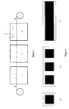
- Figure 1 shows a schematic drawing of a reel-to-reel manufacturing line according to the present invention comprising an integrated coating machine.
- the continuous strip substrate (3) is fed to the screen printer from a feeding roll (1) and guided through three different treatment compartments and then wound up on a receiving roll (2).
- the first treatment compartment is the coating compartment (4) for printing under controlled humidity and temperature.
- the strip substrate is then introduced into the leveling compartment (5) which also provides controlled humidity and temperature. Finally, the printed catalyst layers are dried in a drying compartment (6).
- the manufacturing line from Figure 1 allows printing and leveling under different atmospheres. If the atmospheres for printing and leveling are the same, then the coating and leveling compartment can be combined to form one large compartment comprising a coating section and a leveling section.
- Figure 2 shows possible coating patterns on single sheet substrates (a), and on continuous strips b) and c).
- the feeding roll (1) in Figure 1 must be replaced with an appropriate sheet feeding device and further transport devices for transporting single sheets through the manufacturing line must be provided.
- Receiving roll (2) must be replaced with a single sheet collecting device.
- This example describes the direct coating of an ionomer membrane using a water-based catalyst ink (preparation of a catalyst-coated membrane, CCM).
- a water-based catalyst ink was formulated according to the following composition: 20.0 g Electrocatalyst Elyst A 40 (40 % Pt/C, OMG AG, Hanau) 63.8 g Nafion® ionomer solution (15 wt.% in water) 15.0 g Dipropylene glycol 1.2 g Surfactant Surfynol® 420 (Air Products and Chemicals, Inc.) 100.0 g
- the precious metal-based catalyst was thoroughly mixed with the Nafion solution, then the glycol solvent and the surfactant were added and the catalyst ink was prepared by stirring.
- the coating of catalyst ink onto an ionomer membrane strip (Nation® 112, thickness 50 ⁇ m, width 0.5 m, length 10 m) was performed on a continuous reel-to-reel-coating machine as disclosed in EP 1 037 295 B1.
- the active area to be printed on the front and the back side of the membrane was 100 cm 2 (10 x 10 cm).
- the squeegee area of the screen-printing machine was covered with a sealed compartment , in which a constant relative humidity of 90% at a temperature of 25°C was maintained.
- water vapor mist was continuously added to the compartment by means of an ultrasonic nebulizer. Additionally, a separate leveling chamber was integrated into the reel-to-reel equipment line, which was also supplied with water vapor from the nebulizer. After the printing step, the membrane strip was transported through the separate leveling chamber with controlled humidity (90% relative humidity, 25°C, residence time 2 minutes). The individual print deposits of the screen mesh pattern were leveled and a smooth, continuous catalyst layer was formed. After having passed the leveling chamber, the coated membrane was dried in a belt dryer by means of hot air. The drying conditions were 100°C for 5 minutes. The Pt-loading after the first print was 0.2 mg Pt/cm 2 .
- a second printing step was conducted on the back side of the ionomer membrane.
- the parameters for printing, leveling and drying were identical to the first run..
- the total precious metal loading of the membrane after two printing steps (on front and back side) was 0.5 mg Pt/cm 2 .
- the CCM was cut to an active area of 50 cm 2 and assembled with two un-catalyzed GDLs to form an MEA showing very good results in the PEMFC performance test (hydrogen/air operation, cf. table 1).
- the catalyst ink described in example 1 was used for coating of a GDL substrate.
- the GDL substrate was prepared as follows: A sheet of carbon fiber paper (length 80 cm, width 80 cm, thickness 350 ⁇ m, porosity 85%; supplied by SGL Carbon Group, type SIGRACET) was wet proofed with a water-based PTFE solution (type Hostaflon TF 5032, Dyneon, Gendorf) to a PTFE content of 10 wt.% . After that, a microlayer consisting of carbon black and PTFE was applied to one side of the carbon fiber paper. Then the microlayer-coated surface of the GDL substrate was coated with the water-based catalyst ink by a screen printing process.
- a water-based PTFE solution type Hostaflon TF 5032, Dyneon, Gendorf
- the squeegee area of the screen-printing machine was covered with a sealed compartment, in which a constant relative humidity of 95% at a temperature of 25°C was maintained.
- water vapor mist was continuously added to the compartment by means of an ultrasonic nebulizer.
- the substrate was transferred to a leveling chamber and allowed to level for 2 mins at 95% relative humidity at 25°C.
- the catalysed GDL was dried at 120°C for 10 mins.
- An ionomer membrane Nafion 112 was sandwiched between two of the catalysed GDLs (cutted to an active area of 50 cm 2 ) and hot-pressed at 150°C and 15 bar pressure for 20 seconds to form a 5-layer MEA. This MEA showed very good results in the PEMFC electrochemical testing (cf. table 1).
- the CCMs/MEAs were tested in a PEMFC single cell with an active area of 50 cm 2 running on hydrogen/air feed gases.
- the cell temperature was 80°C, the operating gas pressure was 1.5 bar.
- Anode humidification was 80°C, cathode humidification was 60°C and stoichiometries were 1.5 (anode) / 2 (cathode).
- the MEAs based on CCMs and CCBs manufactured according to the present invention possess a high cell voltage in the range of 670 mV at a current density of 600 mA/cm 2 (this results in a power density of about 0.4 W/cm 2 ). Results of electrochemical testing of five-layer MEAs Example 1 Example 2 Cell Voltage @ 600mA/cm 2 (mV) 670 680
Abstract
Description
- The invention relates to the field of electrochemical cells and fuel cells, more specifically to polymer-electrolyte-membrane fuel cells (PEMFC) and direct methanol fuel cells (DMFC) and describes a process for the manufacture of catalyst-coated substrates. The catalyst-coated substrates, e.g. catalyst-coated membranes ("CCMs"), catalyst-coated backings ("CCBs") and other catalyst-coated tape materials, are manu-factured in a new process comprising the application of water-based catalyst inks to the substrates under controlled relative humidity and temperature. In a subsequent step, the substrates are hold at this controlled humidity for a certain period of time to achieve leveling of the ink deposits. After the drying step, very smooth catalyst layers are obtained and the production process is improved.
- The catalyst-coated membranes (CCMs), catalyst-coated backings (CCBs) and catalyst-coated tapes manufactured according to this process can be used for production of three-layer and five-layer membrane-electrode-assemblies (MEAs). These MEAs find use as components for PEMFC and DMFC stacks.
- Fuel cells convert a fuel and an oxidising agent into electricity, heat and water at two spatially separated electrodes. Hydrogen or a hydrogen-rich gas can be used as the fuel and oxygen or air as the oxidising agent. The energy conversion process in the fuel cell is distinguished by particularly high efficiency. For this reason, fuel cells are gaining increasing importance for mobile, stationary and portable applications.
- The polymer electrolyte membrane fuel cell (PEMFC) and the direct methanol fuel cell (DMFC, a variation of the PEMFC, powered directly by methanol instead of hydrogen) are suitable for use as energy converting devices due to their compact design, their power density and high efficiency. The technology of fuel cells is broadly described in the literature, see for example K. Kordesch and G. Simader, "Fuel Cells and its Application", VCH Verlag Chemie, Weinheim (Germany), 1996.
- In the following section, the technical terms used in the present invention are described in greater detail:
- A catalyst-coated membrane (hereinafter abbreviated "CCM") comprises a polymer electrolyte membrane which is provided on both sides with a catalytically active layer. One of the layers takes the form of an anode for the oxidation of hydrogen and the second layer takes the form of a cathode for the reduction of oxygen. As the CCM consists of three layers (anode catalyst layer, ionomer membrane and cathode catalyst layer), it is often referred to as "three-layer MEA".
- Gas diffusion layers ("GDLs"), sometimes referred to as gas diffusion substrates or backings, are placed onto the anode and cathode layers of the CCM in order to bring the gaseous reaction media (hydrogen and air) to the catalytically active layers and, at the same time, to establish an electrical contact. GDLs usually consist of carbon-based substrates, such as carbon fibre paper or carbon fabric, which are highly porous and allow the reaction gases a good access to the electrodes. Furthermore they are hydro-phobic in order to remove the product water from the fuel cell. GDLs can be coated with a microlayer to improve the contact to the membrane. The microlayer usually consists of a mixture of electrically conducting carbon black and a hydrophobic polymer e.g. polytetrafluoroethylene (PTFE). The GDLs can be tailored specifically into anode-type GDLs or cathode-type GDLs, depending on which side they are built into a MEA. Furthermore, they can be coated with a catalyst layer and subsequently laminated to the ionomer membrane. These catalyst-coated GDLs are frequently referred to as "catalyst-coated backings" (abbreviated "CCBs") or gas diffusion electrodes ("GDEs").
- A membrane-electrode-assembly ("five-layer MEA") is the central component in a polymer-electrolyte-membrane (PEM) fuel cell and consists of five layers: The anode GDL, the anode catalyst layer, the ionomer membrane, the cathode catalyst layer and the cathode GDL. A MEA can be manufactured by combining a CCM with two GDLs (on the anode and the cathode side) or, alternatively, by combining an ionomer membrane with two catalyst-coated backings (CCBs) at the anode and the cathode side. In both cases, a five-layer MEA product is obtained.
- The anode and cathode catalyst layers contain electrocatalysts, which catalyse the respective reaction (oxidation of hydrogen at the anode and reduction of oxygen at the cathode). The metals of the platinum group of the periodic table are preferably used as the catalytically active components. For the most part, supported catalysts are used, in which the catalytically active platinum group metals have been fixed in nano-sized particle form to the surface of a conductive support material. The average particle size of the platinum group metal is between about 1 and 10 nm. Carbon blacks with particle sizes of 10 to 100 nm and high electrical conductivity have proven to be suitable as support materials.
- The polymer electrolyte membrane consists of proton-conducting polymer materials. These materials are also referred to below as ionomers. Tetrafluoroethylene-fluorovinyl-ether copolymer with sulfonic acid groups is preferably used. This material is marketed for example by E.I. DuPont under the trade name Nafion®. However, other, especially fluorine-free, ionomer materials such as sulfonated polyether ketones or aryl ketones or polybenzimidazoles may also be used. Suitable ionomer materials are described by O. Savadogo in "Journal of New Materials for Electrochemical Systems" I, 47-66 (1998). For use in fuel cells, these membranes generally have a thickness from 10 to 200 µm.
- In the "CCM-technology", the catalyst layers are applied directly onto the ionomer membrane resulting in a catalyst-coated membrane (CCM). This method is described for example in
EP 1 037 295 B1,EP 1 176 652 A2 and other pending applications of the applicant. - Alternatively, in the "CCB-technology", the catalyst layers may be applied to the GDL (or "backing") substrates. Two CCBs are then laminated with an ionomer membrane to yield the five-layer MEA.
- In a third route, sometimes referred to as "Decal method" and described for example in EP 0 600 888 B1, the catalyst layers are first applied to a inert substrate, for example a PTFE sheet or blank, dried and then transferred to the surface of an ionomer membrane by means of hot-pressing. The CCMs made by this method are combined with GDLs to form a five-layer MEA.
- Water based catalyst inks are well-known in the literature. EP 731 520 A1 discloses an ink containing catalyst, ionomer, water and optionally up to 10 wt.% of additional organic components. These inks reveal a weak adhesion, predominantly to the surface of ionomer membranes. Furthermore, their leveling and wetting characteristics are very poor. Therefore, the ink deposits form a very rough surface and do not wet the substrate completely. A detailed process for application of these inks is not disclosed.
-
EP 1 176 652 A2 is directed to catalyst inks containing water and linear dialcohols as organic solvents up to a concentration of 50 wt.%. A process for use of these inks is not disclosed. - Additional drawbacks with water-based inks exist on the processing and manufacturing side. The main drawback is the short screen-life of the ink due to rapid evaporation of the main solvent water. This leads to an increase of ink viscosity, which in turn results in a increase of ink deposits on the substrate over the period of operation. Furthermore, the ink dries out very quick on the sceen and this finally causes clogging Qf the screen. Additionally, the print quality is affected, since a poor leveling of the thickened ink occurs and results in weak adhesion to the substrate material.
- There were various efforts made to overcome the drawbacks associated with water-based inks in the past. However, none of these efforts address fuel cell technology or catalyst-containing inks for fuel cell applications.
- In DE-OS 2 105 742, a printing process suitable for inks with rapidly evaporating and toxic solvents is disclosed. A closed compartment above the screen is applied to the screen printing machine to overcome these problems. A device is added to maintain a saturated atmosphere of solvent above the screen.
- In WO 93/03103, water-based chemical compositions suitable for screen printing are described. A method of screen printing with these water-based inks comprising saturating the volume above the printing surface with water vapor is claimed. This printing method is applied for water-based color ink compositions for printing on, for example, textile materials, paper or plastic substrates. A separate leveling step is not disclosed.
- It was an objective of the present invention to provide an application process for water-based catalyst inks onto specialty substrates such as, e.g., ionomer membranes and gas diffusion layers. This application process should overcome the problems with water-based inks listed above and should be straight-forward, simple and fast. Furthermore, an improved formulation of water-based catalyst inks for use in this process should be provided. The application process should be easily scaleable to high-volume manufacturing and applicable to a continuous production line. Last but not least, the process should be environmentally safe and sustainable.
- Thus, a new process for application of water-based catalyst inks to various substrates is provided. These inks can be applied by a printing process (screen printing, stencil printing, offset printing etc.), by doctor-blading, brushing, spraying or by other known coating techniques.
- According to a preferred embodiment of the invention, the coating process is performed on a coating machine with a containment maintaining a controlled humidity in the range of 60 to 100 % relative humidity and at a temperature in the range of 10 to 60°C. Furthermore, the coated substrate is subjected to a leveling process under controlled humidity and temperature conditions e.g. for 1 to 10 minutes. The humidity and temperature in the coating step and the leveling step can be the same or different. The leveling step can be conducted in a second compartment (leveling compartment) or in the same compartment as the coating step. In this fashion, a smooth, uniform catalyst layer with very low surface roughness is achieved.
- Still another aspect of the invention is to provide improved catalyst inks. In order to achieve optimum results in the coating process of the present application, improved water-based catalyst inks should be used. These new, improved water-based catalyst ink compositions preferably comprise at least one specific surfactant with a vapor pressure in the range of 1 to 600 Pascal (Pa) at ambient temperature (20-25°C). The surfactants improve the wetting and leveling characteristics of the ink, particularly to hydrophobic substrate materials, such as polymer films or PTFE-impregnated backings. The high vapor pressure facilitates the removal of the surfactant(s) after the leveling process at slightly elevated temperatures in the drying stage. As a consequence, less surfactant remains in the printed electrode layers; this in turn leads to an improvement in electrical performance of the electrode layers and, consequently, of the MEAs manufactured with these inks. Suitable surfactants for the present invention are materials with vapor pressures in the range of 1 to 600 Pa, preferably in the range of 400 to 600 Pa at 20-25°C. Examples for suitable classes of surfactants are nonionic, anionic or cationic surfactants, such as fluorinated wetting agents (FluoradTM types, manufactured by 3M Co.), tetramethyl-decyn-diol-based wetting agents (SurfynolTM types, manufactured by Air Products and Chemicals Inc.), soya-lecithin-based wetting agents or phospho-amino-lipoides and the like. The vapor pressure of the materials can be determined by standard techniques. Lists of such data are also available e.g. in "CRC Handbook of Chemistry and Physics", CRC Press LLC, Boca Raton (USA).
- The catalyst ink comprises electrocatalyst, ionomer and water as a main solvent in addition to the surfactant. The amount of surfactant added is usually in the range of 0.1 to 20 wt.% based on the total composition of the catalyst ink. In addition, the water-based ink may contain organic solvents, additives, defoamers, pore-forming agents and the like. Mixtures of the listed ingredients as well as mixtures of various surfactants may also be used.
- A preferred water-based catalyst ink contains 5 to 75 wt.% of electrocatalyst, 10 to 75 wt.% of ionomer solution (water-based or organic solvent-based), 10 to 75 wt.% of (e.g. deionized) water, 0 to 50 wt.% of organic solvent and 0.1 to 20 wt.% of surfactant with a vapor pressure of 1 to 600 Pa. Suitable organic solvents are glycols (e.g. ethylene glycol, diethylene glycol, propylene glycol, dipropylene glycol, butanediol and mixtures thereof), alcohols (e.g. C1-4 alcohols, and mixtures thereof), esters (e.g. esters of C1-4 alcohol with C1-4 carboxylic acid and mixtures thereof), aromatic solvents (e.g. benzene or toluene) and aprotic polar solvents (e.g. N-methylpyrrolidone, ethylene carbonate, propylene carbonate, DMSO) and the like. Preferably, glycols are employed.
- The ionomer solutions are commercially available and typically comprise an ionomer in water or an organic solvent. Generally, they contain 5 to 20 wt.-% ionomer. Depending on the type of electrocatalyst, the weight ratio of ionomer to electrocatalyst is usually from 1:1 to 1:15, preferably from 1:1 to 1:10 and more preferably 1:2 to 1:6. The ionomer solution is diluted with water and optionally additional organic solvent to ensure that the resultant ink can be processed.
- Suitable electrocatalysts are e.g. carbon black supported precious metal-based catalysts such as Pt/C or PtRu/C. However precious metal powders and precious metal blacks as well as inorganic oxides containing precious or non-precious metals can be used.
- In a first embodiment of the present invention, the direct coating of substrate such as an ionomer membrane is performed in a continuous roll-to-roll process. A screen-printer comprising a compartment with controlled relative humidity is used for application of the catalyst ink. After printing, the catalyst ink is leveled in a second compartment with the same relative humidity and subsequently dried. According to this process, a catalyst-coated membrane (CCM) is manufactured.
- In a second embodiment of the invention, the catalyst ink is used to prepare a catalyst layer on gas diffusion layers (GDLs) based on a substrate such as a carbon-based material. Again, the application process is performed with a screen-printing device comprising a compartment with controlled relative humidity and a separate compartment for leveling of the ink, however, the process is conducted discontinuously using individual sheets of carbon fiber substrates rather than a substrate in a roll form.
- In a third embodiment of the invention, the catalyst ink is deposited onto an inert transfer medium (for example polyester film or tape) in a continuous reel-to-reel process. After leveling and drying, the catalyst deposit is transferred from the polymer film substrate to the surface of an ionomer membrane as an example of a substrate by means of a hot-pressing/lamination process. The CCM manufactured in this embodiment can be subsequently sandwiched between two GDLs without a catalyst layer to yield a 5-layer MEA.
- Variations of these embodiments are possible. For example, the CCM can be prepared in a combined process by direct coating of the anode layer by screen printing followed by indirect coating of the cathode layer by a tape-transfer process using a catalyst-coated tape and a hot-pressing step. Furthermore, the coating of GDLs as described in the second embodiment can also be performed in a reel-to-reel process.
- In addition to ionomer membranes and carbon fiber substrates, a range of different substrate materials can be coated in the process with water-based catalyst ink. Examples are hydrophobic polymer films (such as polyester, polyimide, polyethylene, PTFE-coated films etc), transfer tape materials, paper-based materials, decal substrates, metal substrate tapes, and the like. These materials can be used in roll form or as individual sheets. Additionally, different methods for the application of catalyst inks can be employed (e.g. stencil printing, offset-printing, transfer printing, doctor-blading, brushing, spraying or other known coating techniques).
- As for ionomer membranes, various types, such as solid uniform membranes, supported membranes on a polymer film, bi-layer membranes, reinforced ionomer membranes as well as composite membranes can be used.
- As for GDLs, various commercially available materials known in fuel cell technology can be processed. Examples are carbon paper, carbon fibers, carbon cloth, woven or nonwoven carbon mesh, needled felt, knitted fabric etc. The porous carbon type supports may be wet proofed and may contain a microlayer.
- Figure 1 and Figure 2 are provided to further explain the invention. Figure 1 shows a schematic drawing of a reel-to-reel manufacturing line according to the present invention comprising an integrated coating machine. The continuous strip substrate (3) is fed to the screen printer from a feeding roll (1) and guided through three different treatment compartments and then wound up on a receiving roll (2). The first treatment compartment is the coating compartment (4) for printing under controlled humidity and temperature. The strip substrate is then introduced into the leveling compartment (5) which also provides controlled humidity and temperature. Finally, the printed catalyst layers are dried in a drying compartment (6).
- The manufacturing line from Figure 1 allows printing and leveling under different atmospheres. If the atmospheres for printing and leveling are the same, then the coating and leveling compartment can be combined to form one large compartment comprising a coating section and a leveling section.
- Figure 2 shows possible coating patterns on single sheet substrates (a), and on continuous strips b) and c). For coating single sheet substrates, the feeding roll (1) in Figure 1 must be replaced with an appropriate sheet feeding device and further transport devices for transporting single sheets through the manufacturing line must be provided. Receiving roll (2) must be replaced with a single sheet collecting device.
- The following examples describe the scope of the invention in more detail. These examples are presented to aid in an understanding of the present invention and are not intended to, and should not be construed to, limit the invention in any way.
- This example describes the direct coating of an ionomer membrane using a water-based catalyst ink (preparation of a catalyst-coated membrane, CCM). A water-based catalyst ink was formulated according to the following composition:
20.0 g Electrocatalyst Elyst A 40 (40 % Pt/C, OMG AG, Hanau) 63.8 g Nafion® ionomer solution (15 wt.% in water) 15.0 g Dipropylene glycol 1.2 g Surfactant Surfynol® 420 (Air Products and Chemicals, Inc.) 100.0 g - The precious metal-based catalyst was thoroughly mixed with the Nafion solution, then the glycol solvent and the surfactant were added and the catalyst ink was prepared by stirring. The coating of catalyst ink onto an ionomer membrane strip (Nation® 112, thickness 50 µm, width 0.5 m, length 10 m) was performed on a continuous reel-to-reel-coating machine as disclosed in
EP 1 037 295 B1. The active area to be printed on the front and the back side of the membrane was 100 cm2 (10 x 10 cm). The squeegee area of the screen-printing machine was covered with a sealed compartment , in which a constant relative humidity of 90% at a temperature of 25°C was maintained. To that purpose, water vapor mist was continuously added to the compartment by means of an ultrasonic nebulizer. Additionally, a separate leveling chamber was integrated into the reel-to-reel equipment line, which was also supplied with water vapor from the nebulizer. After the printing step, the membrane strip was transported through the separate leveling chamber with controlled humidity (90% relative humidity, 25°C,residence time 2 minutes). The individual print deposits of the screen mesh pattern were leveled and a smooth, continuous catalyst layer was formed. After having passed the leveling chamber, the coated membrane was dried in a belt dryer by means of hot air. The drying conditions were 100°C for 5 minutes. The Pt-loading after the first print was 0.2 mg Pt/cm2. - Subsequently, a second printing step was conducted on the back side of the ionomer membrane. The parameters for printing, leveling and drying were identical to the first run.. The total precious metal loading of the membrane after two printing steps (on front and back side) was 0.5 mg Pt/cm2. The CCM was cut to an active area of 50 cm2 and assembled with two un-catalyzed GDLs to form an MEA showing very good results in the PEMFC performance test (hydrogen/air operation, cf. table 1).
- The catalyst ink described in example 1 was used for coating of a GDL substrate. The GDL substrate was prepared as follows: A sheet of carbon fiber paper (length 80 cm, width 80 cm, thickness 350 µm, porosity 85%; supplied by SGL Carbon Group, type SIGRACET) was wet proofed with a water-based PTFE solution (type Hostaflon TF 5032, Dyneon, Gendorf) to a PTFE content of 10 wt.% . After that, a microlayer consisting of carbon black and PTFE was applied to one side of the carbon fiber paper. Then the microlayer-coated surface of the GDL substrate was coated with the water-based catalyst ink by a screen printing process. The squeegee area of the screen-printing machine was covered with a sealed compartment, in which a constant relative humidity of 95% at a temperature of 25°C was maintained. To that purpose, water vapor mist was continuously added to the compartment by means of an ultrasonic nebulizer. After the printing step, the substrate was transferred to a leveling chamber and allowed to level for 2 mins at 95% relative humidity at 25°C. Finally, the catalysed GDL was dried at 120°C for 10 mins. An ionomer membrane (Nafion 112) was sandwiched between two of the catalysed GDLs (cutted to an active area of 50 cm2) and hot-pressed at 150°C and 15 bar pressure for 20 seconds to form a 5-layer MEA. This MEA showed very good results in the PEMFC electrochemical testing (cf. table 1).
- The CCMs/MEAs were tested in a PEMFC single cell with an active area of 50 cm2 running on hydrogen/air feed gases. The cell temperature was 80°C, the operating gas pressure was 1.5 bar. Anode humidification was 80°C, cathode humidification was 60°C and stoichiometries were 1.5 (anode) / 2 (cathode). As shown in table 1, the MEAs based on CCMs and CCBs manufactured according to the present invention possess a high cell voltage in the range of 670 mV at a current density of 600 mA/cm2 (this results in a power density of about 0.4 W/cm2).
Results of electrochemical testing of five-layer MEAs Example 1 Example 2 Cell Voltage @ 600mA/cm2 (mV) 670 680
Claims (13)
- A process for application of a catalyst ink onto a substrate, said ink comprising electrocatalyst, ionomer, water, surfactant and optionally organic solvent, said process comprising the steps of:(a) coating of a catalyst ink to a substrate in a compartment with controlled humidity and temperature;(b) leveling the deposited catalyst ink in a compartment with controlled humidity and temperature; and(c) drying the catalyst-coated substrate at elevated temperatures.
- The process according to claim 1, wherein the application of catalyst ink is performed by screen printing, stencil printing, offset printing, spraying, transfer printing or doctor blading.
- The process according to claim 1, wherein the substrate is based on a polymer film, an ionomer membrane, a carbon fiber, a carbon cloth, a carbon felt or a paper-type material, said substrate being present as an individual sheet or in continuous roll form.
- The process according to claim 1, wherein the coating compartment and the leveling compartment are independently of each other maintained at a humidity of 60 to 100 % relative humidity and at a temperature in the range of 10 to 60°C.
- The process according to any one of claims 1 to 4, wherein the leveling of the deposited catalyst ink is performed for a period of 1 to 10 minutes.
- The process according to claim 1, wherein the drying of the catalyst ink is performed at temperatures in the range of 40 to 150°C for 1 to 10 minutes.
- A device for application of catalyst inks according to any of the preceeding claims, said device comprising a coating machine with a compartment for catalyst ink application and a compartment for leveling of the deposited catalyst ink, said devices being adapted for integration into a continuous manufacturing line.
- The device according to claim 7, wherein the coating compartment and leveling compartment are a single compartment or separate compartments.
- A catalyst-coated membrane for the manufacture of a membrane-electrode- assembly obtainable by the process according to any one of claims 1 to 6.
- A catalyst-coated gas diffusion substrate for the manufacture of a membrane-electrode-assembly obtainable by the process according to any one of claims 1 to 6.
- A catalyst-coated polymer film for the manufacture of a membrane-electrode-assembly obtainable by the process according to any one of claims 1 to 6.
- A membrane-electrode-assembly manufactured by use of a catalyst-coated membrane, a catalyst-coated gas diffusion substrate or a catalyst-coated polymer film obtainable by the process according to any one of claims 1 to 6.
- Use of a membrane-electrode-assembly obtainable by the process according to any one of claims 1 to 6 as a component in a PEMFC or DMFC stack.
Priority Applications (6)
| Application Number | Priority Date | Filing Date | Title |
|---|---|---|---|
| EP02017238.3A EP1387422B1 (en) | 2002-07-31 | 2002-07-31 | Process for the manufacture of catalyst-coated substrates |
| BR0302426-1A BR0302426A (en) | 2002-07-31 | 2003-07-23 | Manufacture of catalyst coated substrates |
| US10/627,238 US20040023105A1 (en) | 2002-07-31 | 2003-07-24 | Process for the manufacture of catalyst-coated substrates and water-based catalyst inks for use therefor |
| KR1020030051259A KR101041734B1 (en) | 2002-07-31 | 2003-07-25 | A process for the manufacture of catalyst-coated substrates, a device for the application of catalyst inks, a composition and a membrane-electrode-assembly comprising the substrate produced by the process, and a method of using the membrane-electrode-assembly |
| CA2436261A CA2436261C (en) | 2002-07-31 | 2003-07-30 | Process for the manufacture of catalyst-coated substrates |
| JP2003283238A JP4896365B2 (en) | 2002-07-31 | 2003-07-30 | Method for applying aqueous catalyst ink onto a substrate, and catalyst coated substrate and membrane electrode assembly obtained thereby |
Applications Claiming Priority (1)
| Application Number | Priority Date | Filing Date | Title |
|---|---|---|---|
| EP02017238.3A EP1387422B1 (en) | 2002-07-31 | 2002-07-31 | Process for the manufacture of catalyst-coated substrates |
Publications (2)
| Publication Number | Publication Date |
|---|---|
| EP1387422A1 true EP1387422A1 (en) | 2004-02-04 |
| EP1387422B1 EP1387422B1 (en) | 2016-04-06 |
Family
ID=30011116
Family Applications (1)
| Application Number | Title | Priority Date | Filing Date |
|---|---|---|---|
| EP02017238.3A Expired - Lifetime EP1387422B1 (en) | 2002-07-31 | 2002-07-31 | Process for the manufacture of catalyst-coated substrates |
Country Status (6)
| Country | Link |
|---|---|
| US (1) | US20040023105A1 (en) |
| EP (1) | EP1387422B1 (en) |
| JP (1) | JP4896365B2 (en) |
| KR (1) | KR101041734B1 (en) |
| BR (1) | BR0302426A (en) |
| CA (1) | CA2436261C (en) |
Cited By (5)
| Publication number | Priority date | Publication date | Assignee | Title |
|---|---|---|---|---|
| FR2892861A1 (en) * | 2005-11-02 | 2007-05-04 | Commissariat Energie Atomique | Fabrication of a continuous catalyst-coated-backing electrode-membrane-electrode assembly for the subsequent fabrication of a proton exchange membrane fuel cell |
| WO2011003884A1 (en) * | 2009-07-07 | 2011-01-13 | Basf Se | Ink comprising polymer particles, electrode, and mea |
| WO2020115450A1 (en) | 2018-12-07 | 2020-06-11 | Compagnie Generale Des Etablissements Michelin | Method for producing a membrane electrode assembly for a fuel cell |
| FR3089693A1 (en) | 2018-12-07 | 2020-06-12 | Compagnie Generale Des Etablissements Michelin | Method of manufacturing a membrane-electrode assembly for a fuel cell |
| WO2023099684A1 (en) * | 2021-12-01 | 2023-06-08 | Fundació Eurecat | Fabrication method of a membrane electrode assembly (mea), mea, cell and uses thereof |
Families Citing this family (22)
| Publication number | Priority date | Publication date | Assignee | Title |
|---|---|---|---|---|
| NL1014696C2 (en) * | 2000-03-20 | 2001-09-28 | Stichting Energie | Manufacture of low-temperature fuel cell electrodes. |
| DE60230979D1 (en) * | 2002-07-31 | 2009-03-12 | Umicore Ag & Co Kg | Aqueous catalyst inks and their use in the preparation of catalyst coated substrates |
| US20050041251A1 (en) * | 2003-08-18 | 2005-02-24 | Hong Cao | Method and apparatus for measuring loading of waterproofing agent in carbon substrate |
| US7153802B2 (en) * | 2004-04-07 | 2006-12-26 | Proton Energy Systems, Inc. | Method of making an electrode for a membrane electrode assembly and method of making the membrane electrode assembly |
| JP4506252B2 (en) * | 2004-04-13 | 2010-07-21 | 富士電機システムズ株式会社 | Manufacturing method of fuel cell and electrode substrate |
| US7041191B2 (en) * | 2004-05-27 | 2006-05-09 | Institute Of Nuclear Energy Research | Method for manufacturing membrane electrode assembly of fuel cell by printing processes |
| US8182884B2 (en) * | 2005-02-28 | 2012-05-22 | GM Global Technology Operations LLC | Process for application of a hydrophilic coating to fuel cell bipolar plates |
| JP2008534719A (en) * | 2005-03-30 | 2008-08-28 | ユミコア・アクチエンゲゼルシャフト・ウント・コムパニー・コマンディットゲゼルシャフト | Ink for producing catalyst layer |
| WO2006111450A1 (en) * | 2005-04-20 | 2006-10-26 | Agfa Graphics Nv | Process for offset printing of a catalytic species via a hydrophilic phase |
| US20060236886A1 (en) * | 2005-04-20 | 2006-10-26 | Agfa-Gevaert | Process for the offset printing of a catalytic species via a hydrophilic phase |
| DE112006002140B4 (en) | 2005-08-12 | 2022-07-14 | GM Global Technology Operations LLC (n. d. Ges. d. Staates Delaware) | Hydrophilic coating for fuel cell bipolar plate and method of making same |
| JP4550784B2 (en) * | 2005-09-28 | 2010-09-22 | 本田技研工業株式会社 | Manufacturing method of electrolyte structure |
| JP5422957B2 (en) * | 2008-09-29 | 2014-02-19 | 大日本印刷株式会社 | Ink for inkjet for forming catalyst layer for fuel cell, catalyst layer for fuel cell and method for producing the same, and catalyst layer-electrolyte membrane laminate |
| WO2011028998A1 (en) * | 2009-09-03 | 2011-03-10 | E. I. Du Pont De Nemours And Company | Improved catalyst coated membranes having composite, thin membranes and thin cathodes for use in direct methanol fuel cells |
| WO2014037828A1 (en) * | 2012-09-06 | 2014-03-13 | Basf Se | Gas-diffusion electrodes for metal-oxygen cells and the production of said electrodes |
| US10022951B2 (en) * | 2014-04-28 | 2018-07-17 | Xerox Corporation | Systems and methods for implementing a vapor condensation technique for delivering a uniform layer of dampening solution in an image forming device using a variable data digital lithographic printing process |
| US9819029B2 (en) * | 2016-02-15 | 2017-11-14 | Doosan Fuel Cell America, Inc. | Method of making a fuel cell component |
| WO2020056368A1 (en) * | 2018-09-14 | 2020-03-19 | Sila Nanotechnologies, Inc. | Battery electrode composition comprising biomass-derived carbon |
| DE102019212134A1 (en) * | 2019-08-13 | 2021-02-18 | Robert Bosch Gmbh | Membrane electrode unit for a polymer electrolyte membrane fuel cell with a partial area of a membrane surface free of a catalyst layer of a proton-conducting membrane of the membrane electrode unit |
| CN110581285A (en) * | 2019-09-20 | 2019-12-17 | 东方电气(成都)氢燃料电池科技有限公司 | Catalyst slurry preparation method and device |
| US20230047140A1 (en) * | 2021-08-16 | 2023-02-16 | University Of Tennessee Research Foundation | Electrodes comprising liquid/gas diffusion layers and systems and methods for making and using the same |
| CN116314982B (en) * | 2023-05-16 | 2023-08-11 | 武汉氢能与燃料电池产业技术研究院有限公司 | Proton exchange membrane fuel cell CCM production device and method based on transfer printing process |
Citations (8)
| Publication number | Priority date | Publication date | Assignee | Title |
|---|---|---|---|---|
| DE2105742A1 (en) | 1971-02-08 | 1972-08-31 | Signograph Ges | Printing processes, in particular for screen printing, and apparatus for carrying out the process |
| WO1993003103A1 (en) | 1991-08-09 | 1993-02-18 | Minnesota Mining And Manufacturing Company | Water-based chemical compositions |
| EP0731520A1 (en) | 1995-03-09 | 1996-09-11 | Johnson Matthey Public Limited Company | Materials for use in catalytic electrode manufacture |
| EP0600888B1 (en) | 1991-02-19 | 1997-08-27 | THE REGENTS OF THE UNIVERSITY OF CALIFORNIA as represented by LOS ALAMOS NATIONAL LABORATORY | Membrane catalyst layer for fuel cells |
| US5778789A (en) * | 1996-03-13 | 1998-07-14 | Sun Chemical | Offset lithographic printing process with a water based ink |
| US6073554A (en) * | 1998-02-13 | 2000-06-13 | Cutcher, Sr.; Thomas V. | Ink shield screen printing assembly and process |
| EP1037295A1 (en) * | 1999-03-11 | 2000-09-20 | Degussa-Hüls Aktiengesellschaft | Method for applying electrode layers on a tape-like polymer electrolyte membrane for fuel cells |
| EP1176652A2 (en) | 2000-07-29 | 2002-01-30 | OMG AG & Co. KG | Ink for manufacturing membrane electrode units for PEM fuel cells |
Family Cites Families (6)
| Publication number | Priority date | Publication date | Assignee | Title |
|---|---|---|---|---|
| JPH04331270A (en) * | 1991-05-02 | 1992-11-19 | Chisso Corp | Printing ink composition |
| US5867363A (en) * | 1992-09-18 | 1999-02-02 | Pinnacle Research Institute, Inc. | Energy storage device |
| JP2921785B2 (en) * | 1995-04-05 | 1999-07-19 | キヤノン株式会社 | Recording medium, method for manufacturing the medium, and image forming method |
| DE19837669A1 (en) * | 1998-08-20 | 2000-03-09 | Degussa | Catalyst layer for polymer electrolyte fuel cells |
| JP2003173786A (en) * | 2001-12-05 | 2003-06-20 | Mitsubishi Electric Corp | Forming method and device of catalyst layer for solid polymer fuel cell |
| DE60230979D1 (en) * | 2002-07-31 | 2009-03-12 | Umicore Ag & Co Kg | Aqueous catalyst inks and their use in the preparation of catalyst coated substrates |
-
2002
- 2002-07-31 EP EP02017238.3A patent/EP1387422B1/en not_active Expired - Lifetime
-
2003
- 2003-07-23 BR BR0302426-1A patent/BR0302426A/en not_active Application Discontinuation
- 2003-07-24 US US10/627,238 patent/US20040023105A1/en not_active Abandoned
- 2003-07-25 KR KR1020030051259A patent/KR101041734B1/en not_active IP Right Cessation
- 2003-07-30 JP JP2003283238A patent/JP4896365B2/en not_active Expired - Fee Related
- 2003-07-30 CA CA2436261A patent/CA2436261C/en not_active Expired - Fee Related
Patent Citations (9)
| Publication number | Priority date | Publication date | Assignee | Title |
|---|---|---|---|---|
| DE2105742A1 (en) | 1971-02-08 | 1972-08-31 | Signograph Ges | Printing processes, in particular for screen printing, and apparatus for carrying out the process |
| EP0600888B1 (en) | 1991-02-19 | 1997-08-27 | THE REGENTS OF THE UNIVERSITY OF CALIFORNIA as represented by LOS ALAMOS NATIONAL LABORATORY | Membrane catalyst layer for fuel cells |
| WO1993003103A1 (en) | 1991-08-09 | 1993-02-18 | Minnesota Mining And Manufacturing Company | Water-based chemical compositions |
| EP0731520A1 (en) | 1995-03-09 | 1996-09-11 | Johnson Matthey Public Limited Company | Materials for use in catalytic electrode manufacture |
| US5778789A (en) * | 1996-03-13 | 1998-07-14 | Sun Chemical | Offset lithographic printing process with a water based ink |
| US6073554A (en) * | 1998-02-13 | 2000-06-13 | Cutcher, Sr.; Thomas V. | Ink shield screen printing assembly and process |
| EP1037295A1 (en) * | 1999-03-11 | 2000-09-20 | Degussa-Hüls Aktiengesellschaft | Method for applying electrode layers on a tape-like polymer electrolyte membrane for fuel cells |
| EP1037295B1 (en) | 1999-03-11 | 2001-06-13 | dmc2 Degussa Metals Catalysts Cerdec AG | Method for applying electrode layers on a tape-like polymer electrolyte membrane for fuel cells |
| EP1176652A2 (en) | 2000-07-29 | 2002-01-30 | OMG AG & Co. KG | Ink for manufacturing membrane electrode units for PEM fuel cells |
Non-Patent Citations (1)
| Title |
|---|
| O. SAVADOGO, JOURNAL OF NEW MATERIALS FOR ELECTROCHEMICAL SYSTEMS, vol. I, 1998, pages 47 - 66 |
Cited By (6)
| Publication number | Priority date | Publication date | Assignee | Title |
|---|---|---|---|---|
| FR2892861A1 (en) * | 2005-11-02 | 2007-05-04 | Commissariat Energie Atomique | Fabrication of a continuous catalyst-coated-backing electrode-membrane-electrode assembly for the subsequent fabrication of a proton exchange membrane fuel cell |
| WO2007051775A1 (en) * | 2005-11-02 | 2007-05-10 | Commissariat A L'energie Atomique | Method for continuously producing a ccb electrode-membrane-electrode assembly |
| WO2011003884A1 (en) * | 2009-07-07 | 2011-01-13 | Basf Se | Ink comprising polymer particles, electrode, and mea |
| WO2020115450A1 (en) | 2018-12-07 | 2020-06-11 | Compagnie Generale Des Etablissements Michelin | Method for producing a membrane electrode assembly for a fuel cell |
| FR3089693A1 (en) | 2018-12-07 | 2020-06-12 | Compagnie Generale Des Etablissements Michelin | Method of manufacturing a membrane-electrode assembly for a fuel cell |
| WO2023099684A1 (en) * | 2021-12-01 | 2023-06-08 | Fundació Eurecat | Fabrication method of a membrane electrode assembly (mea), mea, cell and uses thereof |
Also Published As
| Publication number | Publication date |
|---|---|
| JP4896365B2 (en) | 2012-03-14 |
| US20040023105A1 (en) | 2004-02-05 |
| JP2004071564A (en) | 2004-03-04 |
| KR101041734B1 (en) | 2011-06-16 |
| KR20040012498A (en) | 2004-02-11 |
| EP1387422B1 (en) | 2016-04-06 |
| BR0302426A (en) | 2004-09-08 |
| CA2436261C (en) | 2014-04-22 |
| CA2436261A1 (en) | 2004-01-31 |
Similar Documents
| Publication | Publication Date | Title |
|---|---|---|
| EP1387422B1 (en) | Process for the manufacture of catalyst-coated substrates | |
| EP1387423B1 (en) | Water-based catalyst inks and their use for manufacture of catalyst-coated substrates | |
| EP1369948B1 (en) | Process for the manufacture of membrane-electrode-assemblies using catalyst-coated membranes and adhesives | |
| US6998149B2 (en) | Process for producing a membrane electrode assembly for fuel cells | |
| US8017281B2 (en) | Membrane-electrode assembly for fuel cell with catalyst layer having a first and a second porosity | |
| US8507151B2 (en) | Membrane electrode assembly having low surface ionomer concentration | |
| US6933003B2 (en) | Method of making membrane electrode assemblies | |
| US20140315121A1 (en) | Method for the preparation of catalyst-coated membranes method for the preparation of catalyst-coated membranes | |
| US7285307B2 (en) | Process for producing catalyst-coated membranes and membrane-electrode assemblies for fuel cells | |
| US20110097651A1 (en) | Membrane Electrode Assembly (MEA) Fabrication Procedure on Polymer Electrolyte Membrane Fuel Cell | |
| JP2010505222A (en) | Structure for gas diffusion electrode | |
| CA2683867A1 (en) | Production process of polymer electrolyte membrane for solid polymer electrolyte fuel cell, membrane electrode assembly for solid polymer electrolyte fuel cell, and solid polymer electrolyte fuel cell | |
| CA2688060A1 (en) | Membrane electrode assembly for fuel cell | |
| EP1365464B1 (en) | Continuous process for manufacture of gas diffusion layers for fuel cells | |
| JP2006079904A (en) | Polymer electrolyte fuel cell and its manufacturing method | |
| US20100167160A1 (en) | Method For Producing Polymer Electrolyte Membrane For Solid Polymer Fuel Cell, Membrane Eelctrode Assembly For Solid Polymer Fuel Cell, and Solid Polymer Fuel Cell | |
| EP3664209B1 (en) | Manufacturing method for membrane electrode assembly, and stacked body | |
| KR20090030104A (en) | Membrane-electrode assembly for fuel cell, method of producing same and fuel cell system including same | |
| KR20080045420A (en) | Method of producing membrane-electrode assembly |
Legal Events
| Date | Code | Title | Description |
|---|---|---|---|
| PUAI | Public reference made under article 153(3) epc to a published international application that has entered the european phase |
Free format text: ORIGINAL CODE: 0009012 |
|
| 17P | Request for examination filed |
Effective date: 20020830 |
|
| AK | Designated contracting states |
Kind code of ref document: A1 Designated state(s): AT BE BG CH CY CZ DE DK EE ES FI FR GB GR IE IT LI LU MC NL PT SE SK TR |
|
| AX | Request for extension of the european patent |
Extension state: AL LT LV MK RO SI |
|
| AKX | Designation fees paid |
Designated state(s): AT BE BG CH CY CZ DE DK EE ES FI FR GB GR IE IT LI LU MC NL PT SE SK TR |
|
| 17Q | First examination report despatched |
Effective date: 20070119 |
|
| RIC1 | Information provided on ipc code assigned before grant |
Ipc: B01J 23/40 20060101ALN20150630BHEP Ipc: B01J 37/02 20060101ALI20150630BHEP Ipc: C25B 9/10 20060101ALI20150630BHEP Ipc: B01J 35/06 20060101AFI20150630BHEP Ipc: B41M 1/12 20060101ALN20150630BHEP Ipc: H01M 4/88 20060101ALI20150630BHEP Ipc: B41M 3/00 20060101ALN20150630BHEP Ipc: H01M 4/86 20060101ALN20150630BHEP Ipc: H01M 8/10 20060101ALN20150630BHEP Ipc: B41M 1/06 20060101ALN20150630BHEP Ipc: B41M 1/30 20060101ALN20150630BHEP |
|
| REG | Reference to a national code |
Ref country code: DE Ref legal event code: R079 Ref document number: 60247930 Country of ref document: DE Free format text: PREVIOUS MAIN CLASS: H01M0004880000 Ipc: B01J0035060000 |
|
| GRAP | Despatch of communication of intention to grant a patent |
Free format text: ORIGINAL CODE: EPIDOSNIGR1 |
|
| INTG | Intention to grant announced |
Effective date: 20150925 |
|
| RIC1 | Information provided on ipc code assigned before grant |
Ipc: H01M 8/10 20060101ALN20150911BHEP Ipc: C25B 9/10 20060101ALI20150911BHEP Ipc: H01M 4/88 20060101ALI20150911BHEP Ipc: B41M 1/06 20060101ALN20150911BHEP Ipc: B01J 35/06 20060101AFI20150911BHEP Ipc: B01J 23/40 20060101ALN20150911BHEP Ipc: B41M 1/12 20060101ALN20150911BHEP Ipc: B41M 3/00 20060101ALN20150911BHEP Ipc: B41M 1/30 20060101ALN20150911BHEP Ipc: H01M 4/86 20060101ALN20150911BHEP Ipc: B01J 37/02 20060101ALI20150911BHEP |
|
| GRAS | Grant fee paid |
Free format text: ORIGINAL CODE: EPIDOSNIGR3 |
|
| GRAA | (expected) grant |
Free format text: ORIGINAL CODE: 0009210 |
|
| AK | Designated contracting states |
Kind code of ref document: B1 Designated state(s): AT BE BG CH CY CZ DE DK EE ES FI FR GB GR IE IT LI LU MC NL PT SE SK TR |
|
| REG | Reference to a national code |
Ref country code: GB Ref legal event code: FG4D |
|
| REG | Reference to a national code |
Ref country code: AT Ref legal event code: REF Ref document number: 787134 Country of ref document: AT Kind code of ref document: T Effective date: 20160415 Ref country code: CH Ref legal event code: EP |
|
| REG | Reference to a national code |
Ref country code: IE Ref legal event code: FG4D |
|
| REG | Reference to a national code |
Ref country code: DE Ref legal event code: R096 Ref document number: 60247930 Country of ref document: DE |
|
| REG | Reference to a national code |
Ref country code: FR Ref legal event code: PLFP Year of fee payment: 15 |
|
| REG | Reference to a national code |
Ref country code: NL Ref legal event code: MP Effective date: 20160406 |
|
| REG | Reference to a national code |
Ref country code: AT Ref legal event code: MK05 Ref document number: 787134 Country of ref document: AT Kind code of ref document: T Effective date: 20160406 |
|
| PGFP | Annual fee paid to national office [announced via postgrant information from national office to epo] |
Ref country code: FR Payment date: 20160613 Year of fee payment: 15 |
|
| PG25 | Lapsed in a contracting state [announced via postgrant information from national office to epo] |
Ref country code: NL Free format text: LAPSE BECAUSE OF FAILURE TO SUBMIT A TRANSLATION OF THE DESCRIPTION OR TO PAY THE FEE WITHIN THE PRESCRIBED TIME-LIMIT Effective date: 20160406 |
|
| PG25 | Lapsed in a contracting state [announced via postgrant information from national office to epo] |
Ref country code: FI Free format text: LAPSE BECAUSE OF FAILURE TO SUBMIT A TRANSLATION OF THE DESCRIPTION OR TO PAY THE FEE WITHIN THE PRESCRIBED TIME-LIMIT Effective date: 20160406 |
|
| PGFP | Annual fee paid to national office [announced via postgrant information from national office to epo] |
Ref country code: GB Payment date: 20160727 Year of fee payment: 15 Ref country code: DE Payment date: 20160726 Year of fee payment: 15 |
|
| PG25 | Lapsed in a contracting state [announced via postgrant information from national office to epo] |
Ref country code: AT Free format text: LAPSE BECAUSE OF FAILURE TO SUBMIT A TRANSLATION OF THE DESCRIPTION OR TO PAY THE FEE WITHIN THE PRESCRIBED TIME-LIMIT Effective date: 20160406 Ref country code: GR Free format text: LAPSE BECAUSE OF FAILURE TO SUBMIT A TRANSLATION OF THE DESCRIPTION OR TO PAY THE FEE WITHIN THE PRESCRIBED TIME-LIMIT Effective date: 20160707 Ref country code: PT Free format text: LAPSE BECAUSE OF FAILURE TO SUBMIT A TRANSLATION OF THE DESCRIPTION OR TO PAY THE FEE WITHIN THE PRESCRIBED TIME-LIMIT Effective date: 20160808 Ref country code: ES Free format text: LAPSE BECAUSE OF FAILURE TO SUBMIT A TRANSLATION OF THE DESCRIPTION OR TO PAY THE FEE WITHIN THE PRESCRIBED TIME-LIMIT Effective date: 20160406 Ref country code: SE Free format text: LAPSE BECAUSE OF FAILURE TO SUBMIT A TRANSLATION OF THE DESCRIPTION OR TO PAY THE FEE WITHIN THE PRESCRIBED TIME-LIMIT Effective date: 20160406 |
|
| PG25 | Lapsed in a contracting state [announced via postgrant information from national office to epo] |
Ref country code: BE Free format text: LAPSE BECAUSE OF FAILURE TO SUBMIT A TRANSLATION OF THE DESCRIPTION OR TO PAY THE FEE WITHIN THE PRESCRIBED TIME-LIMIT Effective date: 20160406 Ref country code: IT Free format text: LAPSE BECAUSE OF FAILURE TO SUBMIT A TRANSLATION OF THE DESCRIPTION OR TO PAY THE FEE WITHIN THE PRESCRIBED TIME-LIMIT Effective date: 20160406 |
|
| REG | Reference to a national code |
Ref country code: DE Ref legal event code: R097 Ref document number: 60247930 Country of ref document: DE |
|
| PG25 | Lapsed in a contracting state [announced via postgrant information from national office to epo] |
Ref country code: DK Free format text: LAPSE BECAUSE OF FAILURE TO SUBMIT A TRANSLATION OF THE DESCRIPTION OR TO PAY THE FEE WITHIN THE PRESCRIBED TIME-LIMIT Effective date: 20160406 Ref country code: EE Free format text: LAPSE BECAUSE OF FAILURE TO SUBMIT A TRANSLATION OF THE DESCRIPTION OR TO PAY THE FEE WITHIN THE PRESCRIBED TIME-LIMIT Effective date: 20160406 Ref country code: SK Free format text: LAPSE BECAUSE OF FAILURE TO SUBMIT A TRANSLATION OF THE DESCRIPTION OR TO PAY THE FEE WITHIN THE PRESCRIBED TIME-LIMIT Effective date: 20160406 Ref country code: CZ Free format text: LAPSE BECAUSE OF FAILURE TO SUBMIT A TRANSLATION OF THE DESCRIPTION OR TO PAY THE FEE WITHIN THE PRESCRIBED TIME-LIMIT Effective date: 20160406 |
|
| PLBE | No opposition filed within time limit |
Free format text: ORIGINAL CODE: 0009261 |
|
| STAA | Information on the status of an ep patent application or granted ep patent |
Free format text: STATUS: NO OPPOSITION FILED WITHIN TIME LIMIT |
|
| REG | Reference to a national code |
Ref country code: CH Ref legal event code: PL |
|
| 26N | No opposition filed |
Effective date: 20170110 |
|
| PG25 | Lapsed in a contracting state [announced via postgrant information from national office to epo] |
Ref country code: MC Free format text: LAPSE BECAUSE OF FAILURE TO SUBMIT A TRANSLATION OF THE DESCRIPTION OR TO PAY THE FEE WITHIN THE PRESCRIBED TIME-LIMIT Effective date: 20160406 |
|
| PG25 | Lapsed in a contracting state [announced via postgrant information from national office to epo] |
Ref country code: LI Free format text: LAPSE BECAUSE OF NON-PAYMENT OF DUE FEES Effective date: 20160731 Ref country code: CH Free format text: LAPSE BECAUSE OF NON-PAYMENT OF DUE FEES Effective date: 20160731 |
|
| REG | Reference to a national code |
Ref country code: IE Ref legal event code: MM4A |
|
| PG25 | Lapsed in a contracting state [announced via postgrant information from national office to epo] |
Ref country code: IE Free format text: LAPSE BECAUSE OF NON-PAYMENT OF DUE FEES Effective date: 20160731 |
|
| PG25 | Lapsed in a contracting state [announced via postgrant information from national office to epo] |
Ref country code: LU Free format text: LAPSE BECAUSE OF NON-PAYMENT OF DUE FEES Effective date: 20160731 |
|
| REG | Reference to a national code |
Ref country code: DE Ref legal event code: R119 Ref document number: 60247930 Country of ref document: DE |
|
| GBPC | Gb: european patent ceased through non-payment of renewal fee |
Effective date: 20170731 |
|
| REG | Reference to a national code |
Ref country code: FR Ref legal event code: ST Effective date: 20180330 |
|
| PG25 | Lapsed in a contracting state [announced via postgrant information from national office to epo] |
Ref country code: DE Free format text: LAPSE BECAUSE OF NON-PAYMENT OF DUE FEES Effective date: 20180201 Ref country code: GB Free format text: LAPSE BECAUSE OF NON-PAYMENT OF DUE FEES Effective date: 20170731 |
|
| PG25 | Lapsed in a contracting state [announced via postgrant information from national office to epo] |
Ref country code: CY Free format text: LAPSE BECAUSE OF FAILURE TO SUBMIT A TRANSLATION OF THE DESCRIPTION OR TO PAY THE FEE WITHIN THE PRESCRIBED TIME-LIMIT Effective date: 20160406 Ref country code: FR Free format text: LAPSE BECAUSE OF NON-PAYMENT OF DUE FEES Effective date: 20170731 |
|
| PG25 | Lapsed in a contracting state [announced via postgrant information from national office to epo] |
Ref country code: TR Free format text: LAPSE BECAUSE OF FAILURE TO SUBMIT A TRANSLATION OF THE DESCRIPTION OR TO PAY THE FEE WITHIN THE PRESCRIBED TIME-LIMIT Effective date: 20160406 |
|
| PG25 | Lapsed in a contracting state [announced via postgrant information from national office to epo] |
Ref country code: BG Free format text: LAPSE BECAUSE OF FAILURE TO SUBMIT A TRANSLATION OF THE DESCRIPTION OR TO PAY THE FEE WITHIN THE PRESCRIBED TIME-LIMIT Effective date: 20160406 |