EP1387233A2 - Flow control device - Google Patents
Flow control device Download PDFInfo
- Publication number
- EP1387233A2 EP1387233A2 EP03007681A EP03007681A EP1387233A2 EP 1387233 A2 EP1387233 A2 EP 1387233A2 EP 03007681 A EP03007681 A EP 03007681A EP 03007681 A EP03007681 A EP 03007681A EP 1387233 A2 EP1387233 A2 EP 1387233A2
- Authority
- EP
- European Patent Office
- Prior art keywords
- flow control
- servo controller
- servo
- circuit
- switch
- Prior art date
- Legal status (The legal status is an assumption and is not a legal conclusion. Google has not performed a legal analysis and makes no representation as to the accuracy of the status listed.)
- Granted
Links
- 238000009499 grossing Methods 0.000 claims description 14
- 239000007788 liquid Substances 0.000 claims description 2
- XEEYBQQBJWHFJM-UHFFFAOYSA-N Iron Chemical group [Fe] XEEYBQQBJWHFJM-UHFFFAOYSA-N 0.000 description 14
- 239000000446 fuel Substances 0.000 description 10
- 239000007789 gas Substances 0.000 description 8
- 238000010586 diagram Methods 0.000 description 7
- 239000003990 capacitor Substances 0.000 description 5
- 238000012544 monitoring process Methods 0.000 description 4
- 238000001514 detection method Methods 0.000 description 2
- 239000012530 fluid Substances 0.000 description 2
- 230000002159 abnormal effect Effects 0.000 description 1
- 230000015556 catabolic process Effects 0.000 description 1
- 239000000567 combustion gas Substances 0.000 description 1
- 230000003111 delayed effect Effects 0.000 description 1
- 230000006866 deterioration Effects 0.000 description 1
- 238000009434 installation Methods 0.000 description 1
Images



Classifications
-
- G—PHYSICS
- G05—CONTROLLING; REGULATING
- G05D—SYSTEMS FOR CONTROLLING OR REGULATING NON-ELECTRIC VARIABLES
- G05D7/00—Control of flow
- G05D7/06—Control of flow characterised by the use of electric means
- G05D7/0617—Control of flow characterised by the use of electric means specially adapted for fluid materials
- G05D7/0629—Control of flow characterised by the use of electric means specially adapted for fluid materials characterised by the type of regulator means
- G05D7/0635—Control of flow characterised by the use of electric means specially adapted for fluid materials characterised by the type of regulator means by action on throttling means
-
- Y—GENERAL TAGGING OF NEW TECHNOLOGICAL DEVELOPMENTS; GENERAL TAGGING OF CROSS-SECTIONAL TECHNOLOGIES SPANNING OVER SEVERAL SECTIONS OF THE IPC; TECHNICAL SUBJECTS COVERED BY FORMER USPC CROSS-REFERENCE ART COLLECTIONS [XRACs] AND DIGESTS
- Y10—TECHNICAL SUBJECTS COVERED BY FORMER USPC
- Y10T—TECHNICAL SUBJECTS COVERED BY FORMER US CLASSIFICATION
- Y10T137/00—Fluid handling
- Y10T137/2931—Diverse fluid containing pressure systems
- Y10T137/2934—Gas lift valves for wells
-
- Y—GENERAL TAGGING OF NEW TECHNOLOGICAL DEVELOPMENTS; GENERAL TAGGING OF CROSS-SECTIONAL TECHNOLOGIES SPANNING OVER SEVERAL SECTIONS OF THE IPC; TECHNICAL SUBJECTS COVERED BY FORMER USPC CROSS-REFERENCE ART COLLECTIONS [XRACs] AND DIGESTS
- Y10—TECHNICAL SUBJECTS COVERED BY FORMER USPC
- Y10T—TECHNICAL SUBJECTS COVERED BY FORMER US CLASSIFICATION
- Y10T137/00—Fluid handling
- Y10T137/7722—Line condition change responsive valves
- Y10T137/7758—Pilot or servo controlled
- Y10T137/7761—Electrically actuated valve
-
- Y—GENERAL TAGGING OF NEW TECHNOLOGICAL DEVELOPMENTS; GENERAL TAGGING OF CROSS-SECTIONAL TECHNOLOGIES SPANNING OVER SEVERAL SECTIONS OF THE IPC; TECHNICAL SUBJECTS COVERED BY FORMER USPC CROSS-REFERENCE ART COLLECTIONS [XRACs] AND DIGESTS
- Y10—TECHNICAL SUBJECTS COVERED BY FORMER USPC
- Y10T—TECHNICAL SUBJECTS COVERED BY FORMER US CLASSIFICATION
- Y10T137/00—Fluid handling
- Y10T137/8158—With indicator, register, recorder, alarm or inspection means
- Y10T137/8225—Position or extent of motion indicator
- Y10T137/8242—Electrical
-
- Y—GENERAL TAGGING OF NEW TECHNOLOGICAL DEVELOPMENTS; GENERAL TAGGING OF CROSS-SECTIONAL TECHNOLOGIES SPANNING OVER SEVERAL SECTIONS OF THE IPC; TECHNICAL SUBJECTS COVERED BY FORMER USPC CROSS-REFERENCE ART COLLECTIONS [XRACs] AND DIGESTS
- Y10—TECHNICAL SUBJECTS COVERED BY FORMER USPC
- Y10T—TECHNICAL SUBJECTS COVERED BY FORMER US CLASSIFICATION
- Y10T137/00—Fluid handling
- Y10T137/8593—Systems
- Y10T137/86292—System with plural openings, one a gas vent or access opening
Definitions
- the present invention relates to a flow control device which includes a flow control valve in order to regulate the flow of a fluid.
- This present invention especially relates to a flow control device which has a linear variable differential transformer for detecting the lift of the flow control valve.
- a flow control valve is installed to control the flow of a liquid.
- a position transmitter or the like is used.
- a position transmitter used for detection of the valve lift converts a vertical motion of a valve cylinder, which opens and closes the flow control valve, into a rotating motion and this rotating motion fluctuates the value of current flowing through a magnetic coil. By measuring the fluctuated current value, the position of the valve cylinder is detected.
- the as-measured value is not a linear value in relation to the position of the valve cylinder. Therefore, precision in detecting the valve lift is inferior. Additionally, this rotating motion wears sliding portions such as the rotating shaft, bearings or the like, bringing about problems of a change of the rotation angle initially set at the time of installation and deterioration of the precision in detection.
- a linear variable differential transformer (LVDT) is used to detect the position of the valve cylinder by directly measuring the vertical motion of the valve cylinder.
- FIG. 5 The internal configuration of a flow control device equipped with this LVDT is shown in FIG. 5.
- two LVDT's 100a and 100b are installed for a valve cylinder 1a which is included in a flow control valve 1.
- the LVDT 100a is provided with an iron core 104a interlocking with the valve cylinder 1a and a primary coil 101a, a secondary coil 102a and a secondary coil 103a that are wound around the iron core 104a.
- the LVDT 100b is provided with an iron core 104b interlocking with the valve cylinder 1a, a primary coil 101b and secondary coils 102b and 103b wound around the iron core 104b.
- the secondary coils 102a and 103a are wound in inverse directions, and are series connected.
- the voltages generated at both ends of this series circuit of the secondary coils 102a and 103a are input into a servo controller 105a.
- an alternating current voltage is fed to the primary coil 101a by the servo controller 105a, generating induced voltages in the secondary coils 102a and 103a in accordance with the magnetic field generated by the primary coil 101a.
- the inductance of each of the secondary coils 102a and 103a varies, depending on the position of the iron core 104a. Since the coils are wound in inverse directions, the voltages generated in the secondary coils 102a and 103a respectively cancel each other and their differential voltage is input into the servo controller 105a. Likewise, in the LVDT 100b, the same operation as in the LVDT 100a is performed, so that the same differential voltage is input into the servo controllers 105a and 105b by the LVDT's 100a and 100b.
- the differential voltages generated by the LVDT's 100a and 100b linearly express the position of the valve cylinder 1a, and precision in measuring the position of the valve cylinder 1a in accordance with the values detected from the differential voltages is improved. Additionally, in the servo controllers 105a and 105b, by comparing the differential voltages produced by each of the LVDT's 100a and 100b with the instruction signals transmitted from CPU 5 to specify the lift of the flow control valve 1 and by monitoring the results of the comparison, a switch SWa is changed over in accordance with the results of monitoring.
- the switch SWa is a switch for selecting which of the servo controllers 105a and 105b gives a control signal to a servo valve 4 that regulates the lift of the flow control valve 1 and it is switched over in accordance with the results of monitoring of each of the servo controllers 105a and 105b. Specifically, when the results of the comparison of the servo controllers 105a and 105b are different from each other and either of the servo controllers 105a and 105b is presumed to be at fault, switching over is controlled so that the servo valve 4 is given a control signal by the servo controller that is presumed not to be at fault.
- a flow control device including a flow control valve which controls the flow of a fluid, first and second servo controllers which generate control signals controlling the lift of the flow control valve based on signals with which the position of the cylinder of the flow control valve is detected and a switch which selects one of the control signals output individually from the first and the second servo controllers and supplies it to the flow control valve
- first and second linear variable differential transformers for detecting a position of said valve cylinder, each comprising a core moving in the same direction as the cylinder of the flow control valve, a primary coil which is fed with an alternating current voltage and two, first and second, secondary coils connected in parallel, where voltages are induced in accordance with the position of the core when said primary coil is energized with a voltage; wherein the first servo controller monitors the voltages generated individually in the primary coil, the first secondary coil and the second secondary coil provided in the first linear variable differential transformer respectively; the second
- FIG. 1 is a block diagram showing the relationship between the gas turbine and the flow control device.
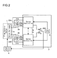
- FIG. 2 is a block diagram showing the relationship among different portions of the flow control device.
- the amount of fuel supply is controlled by a flow control valve 1 and when the fuel is supplied to a combustor 6, combustion gas burnt by the combustor 6 rotates a gas turbine 7.
- the lift of the flow control valve 1 is detected by linear variable differential transformers (LVDT's) 2a and 2b, which will be described later, the detected values are supplied to servo controllers 3a and 3b provided in a control device 3. By operating a servo valve 4 based on the detected values, the lift of the flow control valve 1 is controlled.
- LVDT's linear variable differential transformers
- the flow control device shown in FIG. 2 has the flow control valve 1 which sets the amount of fuel supply, the LVDT's 2a and 2b which detect the lift of the flow control valve 1, the servo controllers 3a and 3b to which the values detected by the LVDT's 2a and 2b are supplied, the servo valve 4 which controls the lift of the flow control valve 1, a CPU 5 which transmits instruction signals specifying the lift of the flow control valve 1 to the servo controllers 3a and 3b and a switch SW which selects a control signal to be supplied to the servo valve 4.
- the servo controllers 3a and 3b, CPU 5 and the switch SW together constitute the control device 3.
- the LVDT 2a is composed of a primary coil 22a and secondary coils 23a and 24a which are wound around an iron core 21a interlocking with a valve cylinder 1a of the flow control valve 1
- the LVDT 2b is composed of a primary coil 22b and secondary coils 23b and 24b wound around an iron core 21b interlocking with the valve cylinder 1a of the flow control valve 1.
- the iron cores 21a and 21b are fitted to the valve cylinder 1a by way of a support 11, and by interlocking with the vertical movement of the valve cylinder 1a, the iron cores 21a and 21b move vertically.
- the servo controllers 3a and 3b are configured as shown in FIG. 4. Because the servo controllers 3a and 3b are of the same configuration, only the servo controller 3a will be explained herein as a representative.
- the servo controller 3a is equipped with an oscillator 31 which supplies a high-frequency electric current to the primary coil 22a; rectifying circuits D1 through D3 that rectify alternating current voltages of the primary coil 22a and the secondary coils 23a and 24a respectively; smoothing capacitors C1 through C3 that smooth the voltages rectified by the rectifying circuits D1 through D3; amplifiers G1 through G3 that amplify the direct current voltages smoothed by the smoothing capacitors C1 through C3; comparators 32a through 32c that compare the output voltages from the amplifiers G1 through G3 to determine whether they are within the range of normal performance or not; delay circuits 33a through 33c which delay the signals transmitted from the comparators 32a through 32c; a subtracting circuit 34 which obtains the difference between the output voltages from the amplifiers G2 and G3; another subtracting circuit 35 which obtains the difference between the output voltage from the subtracting circuit 34 and an instruction signal from CPU 5; a control-signal generating circuit 36 that produces a control
- the value of the alternating current voltages that are generated in the secondary coils 23a and 24a varies and when the center of the iron core 21a is located in the joint portion of the secondary coils 23a and 24a, the inductances of the secondary coils 23a and 24a are equal, so that the alternating current voltages produced in the secondary coils 23a and 24a are equal.
- the voltage energizing the primary coil 22a is converted into a direct current voltage by the rectifying circuit D1 and the smoothing capacitor C1 and supplied to the amplifier G1.
- the voltage induced in the secondary coil 23a is converted into a direct current voltage by the rectifying circuit D2 and the smoothing capacitor C2 and supplied to the amplifier G2
- the voltage induced in the secondary coil 24a is also converted into a direct current voltage by the rectifying circuit D3 and the smoothing capacitor C3 and supplied to the amplifier G3.
- the direct current voltages amplified by the amplifiers G1 through G3 are supplied to the comparators 32a through 32c to determine whether they are within the specified range of voltages or not.
- the range of voltages referred to by the comparator 32a is from Va to Vb
- the range of voltages referred to by the comparators 32b and 32c is from Vc to Vd (0 ⁇ Vc ⁇ Va and Vd > Vb).
- These ranges of voltages from Va to Vb and from Vc to Vd will hereinafter be called the ranges of normal voltages.
- comparators 32a through 32c when the output voltages from the amplifiers G1 through G3 are within the range of normal voltages, they are regarded as normal and the output voltages of the comparators 32a through 32c are set as "Low.” However, when the output voltages from these amplifiers G1 through G3 are out of the range of normal voltages, they are regarded as abnormal and the output voltages the comparators 32a through 32c are set as "High.” After the output voltages from these comparators 32a through 32c are delayed for a specified period of time by the delay circuits 33a through 33c, they are input into the OR circuit 37.
- the voltage energizing the primary coil 22a is zero volt, so that the amplifier G1 outputs zero volt, and thus a fault is recognized in the comparator 32a, turning the output of the delay circuit 33a "High.”
- the primary coil 22a is not energized, and thus the secondary coils 23a and 24a are not induced electro-magnetically, resulting in the output of zero volt from the amplifiers G1 through G3. In consequence, a fault is recognized in the comparators 32a through 32c, turning the outputs of the delay circuits 33a through 33c "High.”
- the output voltages from the amplifiers G2 and G3 are supplied to the subtracting circuit 34, where the output from the amplifier G3 is subtracted from the output from the amplifier G2.
- the voltage obtained by the subtracting circuit 34 is fed to the subtracting circuit 35 as the value detected by the LVDT 2a to determine the lift of the flow control valve 1.
- the output from the subtracting circuit 34 is subtracted from the voltage of the instruction signal supplied by CPU 5 and in this way the parameter on the basis of which to control the lift of the flow control valve 1 is obtained.
- the output voltage from the subtracting circuit 35 is supplied to the control-signal generating circuit 36, where the control signal for PID feedback control is generated with differential components and integral components added thereto on the basis of the output from the subtracting circuit 35.
- This control signal is supplied to the servo valve 4 by way of the switch SW so that the lift of the flow control valve 1 is controlled to be close to the value specified by the instruction signal from CPU 5.
- the outputs from the above-mentioned delay circuits 33a through 33c and a signal indicating a fault in the servo controller 3a are input into the OR circuit 37.
- the signal indicating a fault in the servo controller 3a is "High” when the servo controller 3a is operating abnormally, while it is “Low” when the servo controller 3a is operating normally. Therefore, when one of the outputs from the delay circuits 33a through 33c and the signal indicating a fault in the servo controller 3a is "High”, a "High” signal is output from the OR circuit 37. In other words, when a fault is detected in any of the primary coil 22a, the secondary coils 23a and 24a and the servo controller 3a, a "High” signal is output from the OR circuit 37.
- the output from this OR circuit 37 is supplied to the switch-control circuit 38 as an fault-detecting signal S1 and at the same time, the output from the OR circuit 37 provided in the servo controller 3b is fed to the switch-control circuit 38 as the fault-detecting signal S2.
- These fault-detecting signals S1 and S2 are also fed to the switch-control circuit 38 provided in the servo controller 3b.
- the switch-control circuit 38 provided in the servo controller 3a is "ON" when the servo valve 4 is controlled by the servo controller 3a and the servo controller 3b is in a stand-by state.
- the switch-control circuit 38 provided in the servo controller 3a is in an "OFF" state.
- the switch SW is connected to the contact c so as to prevent control signals from the servo controllers 3a and 3b from being supplied to the servo valve 4 and to stop the control operation of the flow control valve 1, so that the flow control valve 1 does not open in a dangerous direction.
- the flow control valve 1 is instantaneously closed by dumping the emergency trip oil.
- the switch-control circuit 38 provided in the servo controller 3a is turned ON by being fed with a signal by the switch-control circuit 38 provided in the servo controller 3b and additionally a control signal from the servo controller 3a is supplied to the servo valve 4.
- two systems each including an LVDT and a servo controller are installed in a feedback control system for controlling the flow, and when a fault occurs in either of the two systems, feedback control is executed to control the flow by utilizing one system which is operating normally.
- fuel supply is stopped by cutting off the wire transmitting a control signal to the servo valve and by dumping the emergency trip oil from the flow control valve. Consequently, as shown in FIG. 1, when the flow control device of the present invention is utilized for the flow control of fuels supplied to the combustor of a gas turbine, the fuel supply to the combustor can be monitored safely.
- the flow control device in accordance with the embodiment of the present invention has been explained herein as a device for controlling the flow of fuels in the gas turbine system, the present invention is applicable not only to a gas turbine system but also to any other systems.
Landscapes
- Physics & Mathematics (AREA)
- General Physics & Mathematics (AREA)
- Engineering & Computer Science (AREA)
- Automation & Control Theory (AREA)
- Safety Devices In Control Systems (AREA)
- Flow Control (AREA)
- Servomotors (AREA)
Abstract
Description
wherein the first servo controller monitors the voltages generated individually in the primary coil, the first secondary coil and the second secondary coil provided in the first linear variable differential transformer respectively; the second servo controller monitors the voltages generated individually in the primary coil, the first secondary coil and the second secondary coil provided in the second linear variable differential transformer respectively; while the control signal from the first servo controller is being selected by the switch, the switch stops selecting the control signal from the first servo controller on confirming that at least one of the primary coil, the first secondary coil and the second secondary coil provided in the first linear variable differential transformer outputs a voltage out of the range of normal performance; and while the control signal from the second servo controller is being selected by the switch, the switch stops selecting the control signal from the second servo controller on confirming that at least one of the primary coil, the first secondary coil and the second secondary coil provided in the second linear variable differential transformer outputs a voltage out of the range of normal performance.
Claims (7)
- A flow control device including:wherein said first servo controller monitors voltages which are generated individually in said primary coil, said first secondary coil and said second secondary coil provided in said first linear variable differential transformer, and said second servo controller monitors voltages which are generated individually in said primary coil, said first secondary coil and said second secondary coil provided in said second linear variable differential transformer; anda flow control valve controlling a flow of liquid;first and second servo controllers generating control signals to control a lift of said flow control valve based on signals with which a position of a cylinder of said flow control valve is detected; anda switch selecting one of the control signals output individually from said first and second servo controllers so that the selected control signal is supplied to said flow control valve;said flow control device being characterized by further including:first and second linear variable differential transformers for detecting a position of said valve cylinder, each comprising:a core moving in a same direction as a cylinder of said flow control valve;a primary coil fed with an alternating current voltage; andtwo, first and second, secondary coils, connected in parallel, where voltages are induced in accordance with the position of said core when said primary coil is energized with a voltage;
while the control signal transmitted from said first servo controller is being selected by said switch and when it is confirmed that at least one of said primary coil, said first secondary coil and said second secondary coil in provided in said first linear variable differential transformer outputs a voltage out of a range of normal performance, said switch stops selecting the control signal from said first servo controller; and
while the control signal transmitted from said second servo controller is being selected by said switch and when it is confirmed that at least one of said primary coil, said first secondary coil and said second secondary coil provided in said second linear variable differential transformer outputs voltage out of range of normal performance, said switch stops selecting the control signal from said second servo controller. - A flow control device as claimed in claim 1,
wherein said first and second servo controllers each include:wherein, when the control signal transmitted from said first servo controller is being selected by said switch and when an output from said OR circuit provided in said first servo controller is "High," said first servo controller is brought into a stand-by state and furthermore, when an output from said OR circuit provided in said second servo controller is "Low," said switch is changed over so as to select the control signal from said second servo controller; anda first rectifying-and-smoothing circuit rectifying and smoothing an alternating current voltage generated in said primary coil;a second rectifying-and-smoothing circuit rectifying and smoothing an alternating current voltage generated in said first secondary coil;a third rectifying-and-smoothing circuit rectifying and smoothing an alternating current voltage generated in said second secondary coil;first through third comparators, each of which generates a "low" voltage when a direct current voltage output from one of said first through third rectifying-and-smoothing circuits respectively is within a range of normal performance and generates a "high" voltage when the direct current voltage output from one of said rectifying-and-smoothing circuits respectively is out of the range of normal performance; andan OR circuit into which outputs from said first through third comparators are input;
when the control signal transmitted form said second servo controller is being selected by said switch and when the output from said OR circuit provided in said second servo controller is "High," said second servo controller is brought into a stand-by state and furthermore, when the output from said OR circuit provided in said first servo controller is "Low," said switch is changed over so as to select the control signal from said first servo controller. - A flow control device as claimed in claim 2,
wherein, when the outputs from both of said OR circuits provided in said first and second servo controllers are high, emergency trip oil supplied to said flow control valve is dumped to close valve. - A flow control device as claimed in claim 2,
wherein said first and second servo controllers each further include:wherein the lift of said flow control valve is detected based on the difference value determined by said subtracting circuit.a subtracting circuit which determines a difference value between direct current voltages output from said second and third rectifying-and-smoothing circuits, - A flow control device as claimed in claim 4,
wherein, when the outputs from said OR circuits provided in said first and second servo controllers are high, emergency trip oil supplied to said flow control valve is dumped to close valve. - A flow control device as claimed in claim 4,
wherein said first and second servo controllers each further include:a control-signal generating circuit which produces said control signal based on a value obtained by comparing an instruction signal specifying a lift of said flow control valve with the difference value determined by said subtracting circuit. - A flow control device as claimed in claim 6,
wherein, when the outputs of said OR circuits provided in said first and second servo controllers are both high, emergency trip oil supplied to said flow control valve is dumped to close valve.
Applications Claiming Priority (2)
| Application Number | Priority Date | Filing Date | Title |
|---|---|---|---|
| JP2002220610 | 2002-07-30 | ||
| JP2002220610A JP3706601B2 (en) | 2002-07-30 | 2002-07-30 | Flow control device |
Publications (3)
| Publication Number | Publication Date |
|---|---|
| EP1387233A2 true EP1387233A2 (en) | 2004-02-04 |
| EP1387233A3 EP1387233A3 (en) | 2005-08-17 |
| EP1387233B1 EP1387233B1 (en) | 2007-06-13 |
Family
ID=30112913
Family Applications (1)
| Application Number | Title | Priority Date | Filing Date |
|---|---|---|---|
| EP20030007681 Expired - Lifetime EP1387233B1 (en) | 2002-07-30 | 2003-04-03 | Flow control device |
Country Status (6)
| Country | Link |
|---|---|
| US (1) | US6810906B2 (en) |
| EP (1) | EP1387233B1 (en) |
| JP (1) | JP3706601B2 (en) |
| CN (1) | CN1224869C (en) |
| CA (1) | CA2427062C (en) |
| DE (1) | DE60314339T2 (en) |
Cited By (1)
| Publication number | Priority date | Publication date | Assignee | Title |
|---|---|---|---|---|
| CN103752146A (en) * | 2014-01-24 | 2014-04-30 | 天津市振津工程设计咨询有限公司 | System for controlling drying, pressure boosting and pressure reducing process of molecular sieve based on adjusting the opening extend of switch valve |
Families Citing this family (24)
| Publication number | Priority date | Publication date | Assignee | Title |
|---|---|---|---|---|
| GB0109372D0 (en) * | 2001-04-12 | 2001-05-30 | Bevan Engineering Ltd | Rotary bleed valve assembly |
| JP2004211669A (en) * | 2003-01-09 | 2004-07-29 | Toshiba Corp | Servo valve control device and abnormality detection device for servo valve control system |
| JP3814277B2 (en) * | 2004-03-31 | 2006-08-23 | 株式会社コガネイ | Control device for proportional solenoid valve |
| CN100491749C (en) * | 2006-07-14 | 2009-05-27 | 东方电气集团东方汽轮机有限公司 | Power generating equipment regulating valve oil motor servo control system |
| US8265794B2 (en) * | 2007-10-01 | 2012-09-11 | Westlock Controls Corporation | Knowledge based valve control method |
| JP5066474B2 (en) * | 2008-03-31 | 2012-11-07 | アズビル株式会社 | Flow control system |
| JP5409330B2 (en) * | 2009-12-21 | 2014-02-05 | リンナイ株式会社 | Solenoid valve control device |
| US8558408B2 (en) | 2010-09-29 | 2013-10-15 | General Electric Company | System and method for providing redundant power to a device |
| US8278779B2 (en) | 2011-02-07 | 2012-10-02 | General Electric Company | System and method for providing redundant power to a device |
| KR101200264B1 (en) | 2011-02-25 | 2012-11-13 | 두산중공업 주식회사 | System for controlling servo valve of turbine |
| US8698486B2 (en) * | 2011-09-16 | 2014-04-15 | General Electric Company | Methods and systems for use in checking the polarity of multi-coil servos |
| EP2584570A1 (en) * | 2011-10-21 | 2013-04-24 | Metso Paper Inc. | Booster for a digital hydraulic controller and method for using a booster in connection with a digital hydraulic controller |
| US8796982B2 (en) * | 2011-12-15 | 2014-08-05 | Eaton Corporation | System and method for detecting phase loss and diagnosing DC link capacitor health in an adjustable speed drive |
| JP6165778B2 (en) * | 2012-01-27 | 2017-07-19 | カヴリコ コーポレイション | Rotary variable differential transformer (RVDT) sensor assembly with auxiliary output signal |
| FR2992417B1 (en) * | 2012-06-25 | 2015-04-03 | Snecma | MONITORING A LINEAR VARIABLE DIFFERENTIAL TRANSFORMER TYPE SENSOR |
| CN103736364B (en) * | 2014-01-24 | 2016-06-22 | 天津市振津石油天然气工程有限公司 | Based on to the buck system that in molecular sieve drying, switch valve is carried out aperture control |
| EP3619477B1 (en) * | 2017-05-01 | 2024-03-13 | Johnson Controls Tyco IP Holdings LLP | Flow control device for an hvac system |
| US11460869B2 (en) * | 2017-07-31 | 2022-10-04 | Fujikin Incorporated | Fluid control system and flow rate measurement method |
| CN111140482B (en) * | 2018-11-06 | 2022-01-21 | 研能科技股份有限公司 | Micro fluid delivery module |
| CN111140481B (en) * | 2018-11-06 | 2022-01-25 | 研能科技股份有限公司 | Micro fluid delivery module |
| EP3686563B1 (en) * | 2019-01-28 | 2022-10-26 | Ratier-Figeac SAS | Redundant vdt with dc interface |
| CN110707662A (en) * | 2019-11-12 | 2020-01-17 | 西安子国微科技有限公司 | A Servo Control System Based on Hardware PID |
| CN111927572B (en) * | 2020-06-18 | 2022-07-05 | 华电电力科学研究院有限公司 | System and method for measuring total closing time of steam turbine regulating valve |
| CN112697174B (en) * | 2020-12-14 | 2022-11-29 | 潍柴动力股份有限公司 | Measuring method and measuring circuit |
Family Cites Families (8)
| Publication number | Priority date | Publication date | Assignee | Title |
|---|---|---|---|---|
| US4017056A (en) * | 1976-02-23 | 1977-04-12 | Westinghouse Electric Corporation | Servo control system for electro-hydraulic inlet valves |
| US4487079A (en) * | 1983-02-22 | 1984-12-11 | Comptrol, Incorporated | Dual range force transducer |
| US5109675A (en) * | 1990-10-10 | 1992-05-05 | Westinghouse Electric Corp. | Valve position sensing circuit |
| US5322003A (en) * | 1992-09-30 | 1994-06-21 | The United States Of America As Represented By The Secretary Of The Navy | Modular hydraulic control system |
| DE69601404T2 (en) * | 1995-10-16 | 1999-06-10 | Texas Instruments Inc., Dallas, Tex. | Circuit for a variable differential transformer and operating method |
| JPH11236824A (en) | 1998-02-20 | 1999-08-31 | Mitsubishi Heavy Ind Ltd | Fuel gas heating control system for gas turbine |
| DE19853789C1 (en) * | 1998-11-21 | 2000-02-03 | Mtu Muenchen Gmbh | Difference pressure indicator for gas turbine drive unit |
| US7138794B1 (en) * | 2000-03-10 | 2006-11-21 | General Electric Company | Detection of faults in linear and rotary voltage transducers |
-
2002
- 2002-07-30 JP JP2002220610A patent/JP3706601B2/en not_active Expired - Lifetime
-
2003
- 2003-03-24 US US10/393,948 patent/US6810906B2/en not_active Expired - Lifetime
- 2003-04-03 DE DE2003614339 patent/DE60314339T2/en not_active Expired - Lifetime
- 2003-04-03 EP EP20030007681 patent/EP1387233B1/en not_active Expired - Lifetime
- 2003-04-28 CA CA 2427062 patent/CA2427062C/en not_active Expired - Lifetime
- 2003-05-22 CN CNB031410197A patent/CN1224869C/en not_active Expired - Lifetime
Cited By (1)
| Publication number | Priority date | Publication date | Assignee | Title |
|---|---|---|---|---|
| CN103752146A (en) * | 2014-01-24 | 2014-04-30 | 天津市振津工程设计咨询有限公司 | System for controlling drying, pressure boosting and pressure reducing process of molecular sieve based on adjusting the opening extend of switch valve |
Also Published As
| Publication number | Publication date |
|---|---|
| CN1224869C (en) | 2005-10-26 |
| JP3706601B2 (en) | 2005-10-12 |
| CA2427062C (en) | 2005-12-20 |
| DE60314339D1 (en) | 2007-07-26 |
| CN1472612A (en) | 2004-02-04 |
| US6810906B2 (en) | 2004-11-02 |
| CA2427062A1 (en) | 2004-01-30 |
| EP1387233B1 (en) | 2007-06-13 |
| DE60314339T2 (en) | 2008-02-21 |
| EP1387233A3 (en) | 2005-08-17 |
| JP2004062558A (en) | 2004-02-26 |
| US20040020532A1 (en) | 2004-02-05 |
Similar Documents
| Publication | Publication Date | Title |
|---|---|---|
| US6810906B2 (en) | Flow control device | |
| US5109675A (en) | Valve position sensing circuit | |
| KR101692196B1 (en) | Electric motor control device and control method | |
| US8687394B2 (en) | Aircraft power supply and method of operating the same | |
| US7138794B1 (en) | Detection of faults in linear and rotary voltage transducers | |
| JP2009142115A (en) | Motor control device and failure detection method thereof | |
| JP7118660B2 (en) | DISCONNECTION DETECTION SYSTEM FOR DIFFERENTIAL TRANSFORMER DISPLACEMENT GAUGE, DIFFERENTIAL TRANSFORMER DISPLACEMENT GAUGE, AND DISCONNECTION DETECTION METHOD | |
| US5734269A (en) | Bridge circuit fault monitoring apparatus using an output signal level from a bridge circuit and a power source current level to determine faults | |
| JP4637953B2 (en) | Switch status monitoring device | |
| WO2014034117A1 (en) | Zero-phase-sequence current transformer, ground-fault current detection device, power conditioner, and method of detecting malfunction of zero-phase-sequence current transformer | |
| US6181112B1 (en) | Apparatus and method for limiting generator peak voltage | |
| JP2898621B1 (en) | Displacement detector | |
| CN117353442B (en) | Switching control method of dual-power auxiliary switching device | |
| CN116753234B (en) | Magnetic suspension bearing redundant circuit and control method | |
| US8841906B2 (en) | Current sensor and method for detecting a currentless state | |
| GB2257524A (en) | Device for detecting defects in sensors | |
| JP2000213666A (en) | Hydraulic servo control device | |
| JP2010202364A (en) | Elevator control device | |
| KR100749854B1 (en) | A control apparatus for electric rolling stock | |
| JP2022041099A (en) | Protection system | |
| JP2005164241A (en) | Air conditioner control device | |
| JP2007288829A (en) | Machine abnormality detection method and apparatus | |
| JPH04242174A (en) | Trouble discriminator for detector | |
| CN121251756A (en) | Flywheel energy storage equipment stabilizing system based on magnetic suspension-mechanical hybrid bearing | |
| JP2024164989A (en) | Non-contact power supply device |
Legal Events
| Date | Code | Title | Description |
|---|---|---|---|
| PUAI | Public reference made under article 153(3) epc to a published international application that has entered the european phase |
Free format text: ORIGINAL CODE: 0009012 |
|
| 17P | Request for examination filed |
Effective date: 20030403 |
|
| AK | Designated contracting states |
Kind code of ref document: A2 Designated state(s): AT BE BG CH CY CZ DE DK EE ES FI FR GB GR HU IE IT LI LU MC NL PT RO SE SI SK TR |
|
| AX | Request for extension of the european patent |
Extension state: AL LT LV MK |
|
| PUAL | Search report despatched |
Free format text: ORIGINAL CODE: 0009013 |
|
| AK | Designated contracting states |
Kind code of ref document: A3 Designated state(s): AT BE BG CH CY CZ DE DK EE ES FI FR GB GR HU IE IT LI LU MC NL PT RO SE SI SK TR |
|
| AX | Request for extension of the european patent |
Extension state: AL LT LV MK |
|
| RIC1 | Information provided on ipc code assigned before grant |
Ipc: 7G 05D 7/06 A Ipc: 7G 01D 5/22 B Ipc: 7F 16K 31/42 B |
|
| AKX | Designation fees paid |
Designated state(s): CH DE FR GB IT LI |
|
| GRAP | Despatch of communication of intention to grant a patent |
Free format text: ORIGINAL CODE: EPIDOSNIGR1 |
|
| GRAS | Grant fee paid |
Free format text: ORIGINAL CODE: EPIDOSNIGR3 |
|
| GRAA | (expected) grant |
Free format text: ORIGINAL CODE: 0009210 |
|
| AK | Designated contracting states |
Kind code of ref document: B1 Designated state(s): CH DE FR GB IT LI |
|
| PG25 | Lapsed in a contracting state [announced via postgrant information from national office to epo] |
Ref country code: LI Free format text: LAPSE BECAUSE OF FAILURE TO SUBMIT A TRANSLATION OF THE DESCRIPTION OR TO PAY THE FEE WITHIN THE PRESCRIBED TIME-LIMIT Effective date: 20070613 Ref country code: CH Free format text: LAPSE BECAUSE OF FAILURE TO SUBMIT A TRANSLATION OF THE DESCRIPTION OR TO PAY THE FEE WITHIN THE PRESCRIBED TIME-LIMIT Effective date: 20070613 |
|
| REG | Reference to a national code |
Ref country code: GB Ref legal event code: FG4D |
|
| REG | Reference to a national code |
Ref country code: CH Ref legal event code: EP |
|
| REF | Corresponds to: |
Ref document number: 60314339 Country of ref document: DE Date of ref document: 20070726 Kind code of ref document: P |
|
| REG | Reference to a national code |
Ref country code: CH Ref legal event code: PL |
|
| EN | Fr: translation not filed | ||
| PLBE | No opposition filed within time limit |
Free format text: ORIGINAL CODE: 0009261 |
|
| STAA | Information on the status of an ep patent application or granted ep patent |
Free format text: STATUS: NO OPPOSITION FILED WITHIN TIME LIMIT |
|
| PG25 | Lapsed in a contracting state [announced via postgrant information from national office to epo] |
Ref country code: IT Free format text: LAPSE BECAUSE OF FAILURE TO SUBMIT A TRANSLATION OF THE DESCRIPTION OR TO PAY THE FEE WITHIN THE PRESCRIBED TIME-LIMIT Effective date: 20070613 |
|
| 26N | No opposition filed |
Effective date: 20080314 |
|
| PG25 | Lapsed in a contracting state [announced via postgrant information from national office to epo] |
Ref country code: FR Free format text: LAPSE BECAUSE OF FAILURE TO SUBMIT A TRANSLATION OF THE DESCRIPTION OR TO PAY THE FEE WITHIN THE PRESCRIBED TIME-LIMIT Effective date: 20080208 |
|
| GBPC | Gb: european patent ceased through non-payment of renewal fee |
Effective date: 20080403 |
|
| PG25 | Lapsed in a contracting state [announced via postgrant information from national office to epo] |
Ref country code: GB Free format text: LAPSE BECAUSE OF NON-PAYMENT OF DUE FEES Effective date: 20080403 |
|
| REG | Reference to a national code |
Ref country code: DE Ref legal event code: R082 Ref document number: 60314339 Country of ref document: DE Representative=s name: PATENTANWAELTE HENKEL, BREUER & PARTNER, DE Ref country code: DE Ref legal event code: R081 Ref document number: 60314339 Country of ref document: DE Owner name: MITSUBISHI HITACHI POWER SYSTEMS, LTD., YOKOHA, JP Free format text: FORMER OWNER: MITSUBISHI HEAVY INDUSTRIES, LTD., TOKYO, JP |
|
| PGFP | Annual fee paid to national office [announced via postgrant information from national office to epo] |
Ref country code: DE Payment date: 20220302 Year of fee payment: 20 |
|
| REG | Reference to a national code |
Ref country code: DE Ref legal event code: R071 Ref document number: 60314339 Country of ref document: DE |