EP1387179A2 - Printed circuit board integrated with a two-axis fluxgate sensor and method for manufacturing the same - Google Patents
Printed circuit board integrated with a two-axis fluxgate sensor and method for manufacturing the same Download PDFInfo
- Publication number
- EP1387179A2 EP1387179A2 EP03254597A EP03254597A EP1387179A2 EP 1387179 A2 EP1387179 A2 EP 1387179A2 EP 03254597 A EP03254597 A EP 03254597A EP 03254597 A EP03254597 A EP 03254597A EP 1387179 A2 EP1387179 A2 EP 1387179A2
- Authority
- EP
- European Patent Office
- Prior art keywords
- coils
- pick
- soft magnetic
- bars
- excitation
- Prior art date
- Legal status (The legal status is an assumption and is not a legal conclusion. Google has not performed a legal analysis and makes no representation as to the accuracy of the status listed.)
- Granted
Links
Images


Classifications
-
- H—ELECTRICITY
- H05—ELECTRIC TECHNIQUES NOT OTHERWISE PROVIDED FOR
- H05K—PRINTED CIRCUITS; CASINGS OR CONSTRUCTIONAL DETAILS OF ELECTRIC APPARATUS; MANUFACTURE OF ASSEMBLAGES OF ELECTRICAL COMPONENTS
- H05K1/00—Printed circuits
- H05K1/16—Printed circuits incorporating printed electric components, e.g. printed resistors, capacitors or inductors
-
- G—PHYSICS
- G01—MEASURING; TESTING
- G01R—MEASURING ELECTRIC VARIABLES; MEASURING MAGNETIC VARIABLES
- G01R33/00—Arrangements or instruments for measuring magnetic variables
- G01R33/02—Measuring direction or magnitude of magnetic fields or magnetic flux
- G01R33/04—Measuring direction or magnitude of magnetic fields or magnetic flux using the flux-gate principle
-
- Y—GENERAL TAGGING OF NEW TECHNOLOGICAL DEVELOPMENTS; GENERAL TAGGING OF CROSS-SECTIONAL TECHNOLOGIES SPANNING OVER SEVERAL SECTIONS OF THE IPC; TECHNICAL SUBJECTS COVERED BY FORMER USPC CROSS-REFERENCE ART COLLECTIONS [XRACs] AND DIGESTS
- Y10—TECHNICAL SUBJECTS COVERED BY FORMER USPC
- Y10T—TECHNICAL SUBJECTS COVERED BY FORMER US CLASSIFICATION
- Y10T29/00—Metal working
- Y10T29/49—Method of mechanical manufacture
- Y10T29/49002—Electrical device making
- Y10T29/4902—Electromagnet, transformer or inductor
- Y10T29/49073—Electromagnet, transformer or inductor by assembling coil and core
Definitions
- the present invention generally relates to a printed circuit board. More particularly, the present invention relates to a printed circuit board integrated with a two-axis fluxgate sensor and a method for manufacturing the same.
- a fluxgate sensor enables a human to indirectly perceive magnetic energy, since magnetic energy is not perceivable by human sense organs, such as eyes or ears.
- a magnetic sensor employing a soft magnetic coil has been conventionally used.
- a magnetic sensor is made by winding a coil around a relatively large bar-shaped core or annular-shaped core, which is formed of a soft magnetic ribbon.
- an electronic circuit is employed to obtain a magnetic field in proportion to the measured magnetic field.
- the conventional fluxgate sensor however, has the following problems, some of which are due to the structure of the conventional fluxgate sensor.
- the coil being wound around the large bar-shaped core or annular-shaped core, which is made of the soft magnetic ribbon, results in high production costs and a large volume of the overall system.
- flux leakage is inevitable in the flux change due to the excitation coil and the detected magnetic field. Accordingly, high sensitivity is not readily achieved.
- a conventional fluxgate sensor for detecting magnetic energy in two axes includes two separate one-axis fluxgate sensors arranged in perpendicular relation with each other, which results in yet another problem of the device size increasing.
- a printed circuit board integrated with a two-axis fluxgate sensor comprising a first soft magnetic core formed lengthwise in a first axial direction, a first excitation coil formed of a metal film and wound around the first soft magnetic core, a first pick-up coil formed of a metal film and wound around the first soft magnetic core and the first excitation coil, a second soft magnetic core formed lengthwise in a second axial direction, the second axial direction being perpendicular to the first axial direction, a second excitation coil formed of a metal film and wound around the second soft magnetic core, a second pick-up coil formed of a metal film and wound around the second soft magnetic core and the second excitation coil, and a pad for establishing conductivity between the first and second excitation coils and the first and second pick-up coils and an external circuit.
- the invention thus provides a printed circuit board integrated with a compact-sized two-axis fluxgate sensor capable of detecting magnetic field in two axes with high accuracy.
- the invention can prevent an induction wave in a flux change detecting coil when the external magnetic field is measured as zero (0).
- the first and second soft magnetic cores either include two parallel bars or a rectangular-ring formed on a same plane.
- the first and second excitation coils have a structure of winding the two bars, or winding both sides of the rectangular-ring in an axial direction respectively, and substantially in a solenoid pattern.
- the first and second excitation coils may have a structure of winding the two bars, or winding both sides of the rectangular-ring in an axial direction alternately and substantially in a figure-eight pattern.
- the first and second pick-up coils have a structure of winding the two bars, or winding both sides of the rectangular-ring in an axial direction together, and substantially in a solenoid pattern.
- the first and second pick-up coils may have a structure of winding the two bars, or winding both sides of the rectangular-ring in an axial direction respectively, and substantially in a solenoid pattern.
- the first and second excitation coils and the first and second pick-up coils may wind around the two bars or the rectangular-ring in an alternating fashion.
- the number of windings of the first and second excitation coils and the first and second pick-up coils is not limited, it is preferred that the first and second excitation coils and the first and second pick-up coils are each wound once.
- the first and second excitation coils and the first and second pick-up coils are preferably wound substantially in a zigzag fashion, such that the first and second excitation coils and the first and second pick-up coils face each other with the intervention of the two bars, or the rectangular-ring, therebetween.
- a method for manufacturing a printed circuit board integrated with a two-axis fluxgate sensor including: (a) forming lower patterns of excitation coils and pick-up coils on both sides of a first substrate, wherein the first substrate is formed by stacking a metal film on both sides of a dielectric substance; (b) sequentially stacking a prepreg and a soft magnetic substance film on each of the lower patterns of the excitation coils and the pick-up coils; (c) forming soft magnetic cores on each of the soft magnetic substance films, the soft magnetic cores on the soft magnetic substance films being in perpendicular relation; (d) forming a second substrate by sequentially stacking a prepreg and a metal film on each side of the soft magnetic cores; (e) forming upper patterns of the excitation coils and the pick-up coils on each of the metal films stacked on both sides of the second substrate, each of the upper patterns corresponding to a respective one of the lower patterns that is formed at the same
- the soft magnetic cores formed on both sides of the second substrate either include two parallel bars formed on a same plane or a rectangular-ring formed on a same plane.
- the excitation coils have a structure of winding the two bars, or winding both sides of the rectangular-ring in an axial direction, respectively, and substantially in a solenoid pattern.
- the excitation coils may have a structure of winding the two bars, or winding both sides of the rectangular-ring in an axial direction alternately, and substantially in a figure-eight pattern.
- the pick-up coils have a structure of winding the two bars, or winding both sides of the rectangular-ring in an axial direction together, and substantially in a solenoid pattern.
- the pick-up coils may have a structure of winding the two bars or winding both sides of the rectangular-ring in an axial direction respectively, and substantially in a solenoid pattern.
- the excitation coils and the pick-up coils may wind around the two bars, or the rectangular-ring, in an alternating fashion. Although the number of winding of the excitation coils and the pick-up coils is not limited, it is preferred that the excitation coils and the pick-up coils are each wound once. In the case that the excitation coils and the pick-up coils are wound once, the excitation coils and the pick-up coils are preferably wound substantially in a zigzag fashion, such that the excitation coils and the pick-up coils face each other with the intervention of the two bars, or the rectangular-ring therebetween.
- the method may further include etching the metal films stacked on both sides of the second substrate to a predetermined thickness prior to forming the upper pattern of the excitation coil and the pick-up coil.
- each of the stages in the method may include applying a photosensitive agent on a predetermined surface; light-exposing according to a predetermined shape; and etching a predetermined location according to the light exposure.
- the two-axis fluxgate sensor is integrated in the printed circuit board, greater compactness of the product may be achieved, while facilitating detection of the magnetic fields in two axes with higher accuracy. Further, no induction voltage occurs in the pick-up coils when the external magnetic field is measured as zero (0). Also according to the present invention, various applications are possible through the integration with other types of sensors and external circuits.
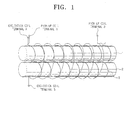
- FIG. 1 illustrates a view of a fluxgate sensor integrated into a printed circuit board according to a preferred embodiment of the present invention.
- the fluxgate sensor has first and second bar-type soft magnetic cores 1 and 2 with an excitation coil 3 being separately wound thereon, and a pick-up coil 4 wound around the first bar-type soft magnetic core 1 and the second bar-type soft magnetic core 2 substantially in a solenoid pattern.
- the winding structure in which the excitation coil 3 is separately wound around the first and second bar-type soft magnetic cores, will be called a "separated structure.”
- the fluxgate sensor may also have a winding structure in which the excitation coil 3 is alternately wound around the two parallel bar-type cores, i.e., the first and second soft magnetic cores 1 and 2 are alternately wound around with the excitation coil 3 substantially in a figure-eight pattern.
- This structure will be referred to as a "united structure.”
- the pick-up coil 4 can either wind the first and second soft magnetic cores 1 and 2 in a solenoid pattern or as in the separated structure. Further, the first and second soft magnetic cores 1 and 2 may be replaced with a rectangular-ring type core.
- FIGS. 2A through 2F are waveforms for explaining the operation of the fluxgate sensor of FIG. 1.
- FIG. 2A is a waveform of the magnetic field H generated from the first soft magnetic core 1.
- FIG. 2B is a waveform of the magnetic field H generated from the second soft magnetic core 2.
- FIG. 2C is a waveform of the flux density B generated from the first soft magnetic core 1.
- FIG. 2D is a waveform of the flux density B generated from the second soft magnetic core 2.
- FIGS. 2E and 2F are waveforms of first and second voltages Vind1 and Vind2 induced at the pick-up coil 4, and the sum of first and second voltages (Vind1+Vind2), respectively.
- the internal magnetic field H of the first bar 1 is represented as 'Hext (external magnetic field) + Hexc (magnetic field by excitation coil).
- the internal magnetic field H of the second bar 2 is represented as 'Hext-Hexc'.
- the flux density B of the first bar 1 is represented as 'Bext (flux density by external flux) + Bexc (flux density by excitation coil)', and the flux density B of the second bar 2 is represented as 'Bext - Bexc'.
- the voltages Vind1 and Vind2 induced at the respective bars 1 and 2 and detected at the pick-up coil 4 are represented as shown in FIG. 2E. Since the pick-up coil 4 is wound to gain the sum of the flux changes at the two bars 1 and 2, the actual voltage detected at the pick-up coil 4 is represented as shown in FIG. 2F, in which the two voltages are offset with respect to one another. In other words, from the direction of the axis of the respective bars 1 and 2, the external flux Hext is applied in the same direction with respect to the two bars 1 and 2. Therefore, by the excited magnetic field Hexc, the internal fluxes of the two bars 1 and 2 are represented as 'Hext + Hexc' and 'Hext - Hexc,' respectively.
- the winding structure of the excitation coil 3 and the pick-up coil 4 is important because the sum of the flux changes at the respective bars 1 and 2 is gained by alternately winding the excitation coil 3 and the pick-up coil 4 on the same plane.
- the structure of the fluxgate sensor described above offsets the induction waves of the magnetic field generated from the first and second bar-type soft magnetic cores 1 and 2 in the absence of the external magnetic field Hext, with the flux generated by the excitation coil forming a closed-magnetic path at the bar-type soft magnetic cores 1 and 2. It is preferable that the excitation coil 3 and the pick-up coil 4 are alternately wound one time, although the number of winding can be varied up to several times.
- Detection of the magnetic field is possible simply by arranging the excitation coil 3 and the pick-up coil 4 on a single soft magnetic core. In this case, an induction voltage is generated at the pick-up coil 4 even in the absence of the external magnetic field 'Hext' due to the excitation coil 3, thus requiring complicated signal processing of the output signal from the pick-up coil 4, such as amplification and filtering. Accordingly, instead of using a single core, it is more advantageous in the signal processing to use two cores or a rectangular-ring type core.
- FIG. 3 is a schematic exploded perspective view of a printed circuit board (PCB) integrated with a two-axis fluxgate sensor according to an embodiment of the present invention.
- the two-axis fluxgate sensor is constructed of two single-axis fluxgate sensors that are stacked on each other in a perpendicular relation.
- Upper and lower patterns 40 of the excitation coil 3 and the pick-up coil 4 are formed on an epoxy resin 30 from the first (i.e., lowest) floor to the third floor, with the two bar-type soft magnetic cores formed of magnetic material 20 being extended on the second floor in a direction of the x-axis.
- Lower and upper patterns 50 of the excitation coil 3 and the pick-up coil 4 are formed on an epoxy resin 30 from the fourth to the sixth (i.e., highest) floors, with the two soft magnetic cores of magnetic material 10 are extended on the fifth floor in a direction of the y-axis.
- the present invention offers an advantage of compact size as the sensors are integrated into the PCB.
- FIGS. 4A through 4L illustrate sectional views depicting stages in the manufacturing process of the two-axis fluxgate sensor integrated in the PCB.
- a photoresist is applied on both sides of a first substrate, which is preferably a copper clad laminate (CCL) board 110.
- the CCL board is constructed of metal films 102 and 103 stacked on both sides of a dielectric substance 101.
- the CCL board 110 is then subjected to light exposure and development, and then the lower pattern 104 of the excitation coil 3 and the pick-up coil 4 is formed through etching and surface processing.
- FIG. 4D a prepreg 105 and a soft-magnetic substance layer 106 are sequentially stacked on both sides of the CCL board 110, where the lower pattern of the excitation coil 3 and the pick-up coil 4 are formed.
- FIG. 4E the photoresist 107 is applied on the soft-magnetic substance layer 106 on both sides, and light exposure and development are carried out.
- FIG. 4F the soft magnetic cores on different floors in perpendicular relation are formed through etching and surface processing. As a result, the second and fifth floors shown in FIG. 3 are formed.
- FIG. 4F the soft magnetic cores on different floors in perpendicular relation are formed through etching and surface processing.
- the prepreg 105 and a metal film 108 are sequentially stacked on the upper side of the soft magnetic cores, forming a second substrate 120. Then, referring to FIG. 4H, the metal film 108 stacked on both sides of the second substrate 120 is subjected to half-etching. Continuously, by applying, light-exposing and developing a photoresist on the metal films 108, the upper pattern of the excitation coil 3 and the pick-up coil 4 corresponding to the lower pattern is formed. Subsequently, referring to FIGS.
- a through hole 109 is formed to open communication of upper and lower patterns of the excitation coil 3 and the pick-up coil 4 formed on the metal films on both sides of the second substrate 120, and then both sides of the second substrate 120 are plated.
- the photoresist is applied on both plated sides to have the upper pattern of the excitation coil 3 and the pick-up coil 4 separately have winding structures, and the process of light exposure, developing, etching and surface processing are performed. As a result, the first and sixth floors of FIG. 2 are formed.
- a pad 111 for establishing conductivity with the external circuit is formed through general processes, and the outer shape is processed.
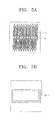
- FIG. 5A through 5F illustrate plan views of each floor of the two-axis fluxgate sensor according to another embodiment of the present invention, showing an upper pattern of the excitation coil 3 and the pick-up coil 4 formed on the same plane for detecting the magnetic field in the direction of the x-axis.
- the shorter lines 1 F-3 represent the upper pattern of the excitation coil 3 wound around the soft magnetic core in the separated structure
- the longer lines 1F-4 represent the upper pattern of the pick-up coil 4 wound around the soft magnetic core.
- FIG. 5B illustrates a plane view of the second floor, showing the soft magnetic core 2F-1 extended lengthwise in the direction of the x-axis to detect the magnetic field in the direction of the x-axis.
- FIG. 3 represents the respective soft magnetic cores 10 and 20 as bar type, the cores 10 and 20 will be depicted as rectangular-ring type in this embodiment.
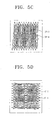
- FIG. 5C illustrates a plan view of the third floor, showing the lower pattern of the excitation coil 3F-3 and the pick-up coil 3F-4 formed to correspond to those of FIG. 5A.
- FIG. 5D illustrates a plan view of the fourth floor, showing the lower pattern of the excitation coil 4F-3 and the pick-up coil 4F-4 formed on the same plane in order to detect a magnetic field in the direction of the y-axis.
- FIG. 5C illustrates a plan view of the third floor, showing the lower pattern of the excitation coil 3F-3 and the pick-up coil 3F-4 formed to correspond to those of FIG. 5A.
- FIG. 5D illustrates a plan view of the fourth floor, showing the lower pattern of the excitation coil 4F-3 and the pick-up coil 4F-4 formed on the same plane in order to detect a magnetic field in the direction of the
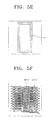
- FIG. 5E illustrates a plan view of the fifth floor, showing the rectangular-ring type soft magnetic core 5F-1 lengthwise extended in the direction of the y-axis to detect a magnetic field in the direction of the y-axis.
- FIG. 5F illustrates a plan view of the sixth floor, showing the upper pattern of the excitation coil 6F-3 and the pick-up coil 6F-4 formed to correspond to the lower portion of the excitation coil 4F-3 and the pick-up coil 4F-4.
- the respective floors are constructed to form a two-axis fluxgate sensor for detecting magnetic fields in the direction of both the x- and y-axes, with a high accuracy.
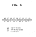
- FIG. 6 illustrates a sectional view showing a winding pattern of the excitation coil and the pick-up coil of a two-axis fluxgate sensor of FIG. 3 in respective axes.
- the excitation coil and the pick-up coil are respectively wound around the soft magnetic core once in a zigzag fashion such that the excitation coil and the pick-up coil face each other with the intervention of the soft magnetic core therebetween.
- a two-axis fluxgate sensor integrated in a PCB as described above may be used in various applications.
- a device may be used in a navigation system by terrestrial magnetism detection, an earth magnetism change monitor (earthquake prediction), a biological electric measurement instrument, or a device for detecting defects in metals.
- the fluxgate sensor may also be used in magnetic encoders, contactless potentiometers, electric current sensors, torque sensors, and displacement sensors.
- a two-axis fluxgate sensor which may be integrated in a PCB together with other sensors and circuits, the overall size of a system may be greatly reduced. Further, power consumption may be minimized.
- the two-axis fluxgate sensor according to the present invention has a high sensitivity to detect a weak external magnetic field through the winding structure of the excitation coil and the pick-up coil alternately wound around the rectangular-ring type or two bar-type soft magnetic cores.
- a further advantage of the fluxgate sensor according to the present invention is that is may be produced at a lower cost than the conventional bar-type or annular cores.
- the fluxgate sensor of the present invention facilitates mass-production.
- the fluxgate sensor has a high sensitivity to the magnetic field.
Landscapes
- Physics & Mathematics (AREA)
- Condensed Matter Physics & Semiconductors (AREA)
- General Physics & Mathematics (AREA)
- Engineering & Computer Science (AREA)
- Microelectronics & Electronic Packaging (AREA)
- Measuring Magnetic Variables (AREA)
- Parts Printed On Printed Circuit Boards (AREA)
- Production Of Multi-Layered Print Wiring Board (AREA)
Abstract
Description
Claims (24)
- A printed circuit board integrated with a two-axis fluxgate sensor, comprising:a first soft magnetic core formed lengthwise in a first axial direction;a first excitation coil formed of a metal film and wound around the first soft magnetic core;a first pick-up coil formed of a metal film and wound around the first soft magnetic core and the first excitation coil;a second soft magnetic core formed lengthwise in a second axial direction, the second axial direction being perpendicular to the first axial direction;a second excitation coil formed of a metal film and wound around the second soft magnetic core;a second pick-up coil formed of a metal film and wound around the second soft magnetic core and the second excitation coil; anda pad for establishing conductivity between the first and second excitation coils and the first and second pick-up coils and an external circuit.
- The printed circuit board as claimed in claim 1, wherein the first and second soft magnetic cores comprise two bars on a same plane.
- The printed circuit board as claimed in claim 2, wherein the two bars are parallel.
- The printed circuit board as claimed in claim 2 or 3, wherein the first and second excitation coils have a structure of winding the two bars substantially in a solenoid pattern.
- The printed circuit board as claimed in claim 2, 3 or 4, wherein the first and second pick-up coils have a structure of winding the two bars together substantially in a solenoid pattern.
- The printed circuit board as claimed in claim 5, wherein the first and second pick-up coils have a structure of winding the two bars together substantially in the solenoid pattern.
- The printed circuit board as claimed in any one of claims 2 to 6, wherein the first and second excitation coils and the first and second pick-up coils wind the two bars in an alternating fashion.
- The printed circuit board as claimed in any one of claims 2 to 7, wherein the first and second excitation coils and the first and second pick-up coils are wound once substantially in a zigzag fashion, such that the first and second excitation coils and the first and second pick-up coils face each other with the intervention of the two bars therebetween.
- The printed circuit board as claimed in any one of claims 2 to 8, wherein the first and second excitation coils have a structure of winding the two bars alternately substantially in a figure-eight pattern.
- The printed circuit board as claimed in any one of claims 2 to 9, wherein the first and second soft magnetic cores comprise a rectangular-ring formed on a same plane, two sides of the rectangular ring defining the two bars.
- The printed circuit board as claimed in claim 10, wherein the two sides of the rectangular-ring are wound in an axial direction.
- A method for manufacturing a printed circuit board integrated with a two-axis fluxgate sensor, comprising:(a) forming lower patterns of excitation coils and pick-up coils on both sides of a first substrate, wherein the first substrate is formed by stacking a metal film on both sides of a dielectric substance;(b) sequentially stacking a prepreg and a soft magnetic substance film on each of the lower patterns of the excitation coils and the pick-up coils;(c) forming soft magnetic cores on each of the soft magnetic substance films, the soft magnetic cores on the soft magnetic substance films being in perpendicular relation;(d) forming a second substrate by sequentially stacking a prepreg and a metal film on each side of the soft magnetic cores;(e) forming upper patterns of the excitation coils and the pick-up coils on each of the metal films stacked on both sides of the second substrate, each of the upper patterns corresponding to a respective one of the lower patterns that is formed at the same side as the respective one of the upper patterns;(f) forming through holes from the upper patterns to the lower patterns formed on each of the metal films on both sides of the second substrate;(g) plating both sides of the second substrate where the through holes are formed;(h) etching the plated sides of the second substrate so that the excitation coils and the pick-up coils are separately formed on both sides with respective winding structures; and(i) forming a pad for establishing conductivity between the excitation coils and the pick-up coils and an external circuit.
- The manufacturing method as claimed in claim 12, wherein the soft magnetic cores formed on both sides of the second substrate comprise two bars formed on a same plane.
- The manufacturing method as claimed in claim 13, wherein the two bars are parallel.
- The manufacturing method as claimed in claim 13 or 14, wherein the excitation coils have a structure of winding the two bars substantially in a solenoid pattern.
- The manufacturing method as claimed in claim 13, 14 or 15, wherein the pick-up coils have a structure of winding the two bars substantially in a solenoid pattern.
- The manufacturing method as claimed in claim 16, wherein the pick-up coils have a structure of winding the two bars together substantially in the solenoid pattern.
- The manufacturing method as claimed in any one of claims 13 to 17, wherein the excitation coils and the pick-up coils wind the two bars in an alternating fashion.
- The manufacturing method as claimed in any one of claims 13 to 18, wherein the excitation coils and pick-up coils are wound once substantially in a zigzag fashion, such that the excitation coils and the pick-up coils face each other with the intervention of the two bars therebetween.
- The manufacturing method as claimed in any one of claims 13 to 19, wherein the excitation coils have a structure of winding the two bar-type soft magnetic cores alternately and substantially in a figure-eight pattern.
- The manufacturing method as claimed in any one of claims 13 to 20, wherein the soft magnetic core comprises a rectangular-ring formed on a same plane, two sides of the rectangular ring defining the two bars.
- The manufacturing method as claimed in claim 21, wherein the two sides of the rectangular-ring are wound in an axial direction.
- The manufacturing method as claimed in any one of claims 12 to 22, wherein forming the upper pattern of the excitation coil and the pick-up coil corresponding to the lower pattern of the excitation coil and the pick-up coil further comprises:etching the metal films stacked on both sides of the second substrate to a predetermined thickness.
- The manufacturing method as claimed in any one of claims 12 to 23, wherein each of (a) through (i) comprise:applying a photosensitive agent on a predetermined surface;light-exposing according to a predetermined shape; andetching a predetermined location according to the light exposure.
Applications Claiming Priority (2)
| Application Number | Priority Date | Filing Date | Title |
|---|---|---|---|
| KR2002045069 | 2002-07-30 | ||
| KR10-2002-0045069A KR100481552B1 (en) | 2002-07-30 | 2002-07-30 | Printed circuit board integrated 2-axis fluxgate sensor and method for manufacturing the same |
Publications (3)
| Publication Number | Publication Date |
|---|---|
| EP1387179A2 true EP1387179A2 (en) | 2004-02-04 |
| EP1387179A3 EP1387179A3 (en) | 2005-07-20 |
| EP1387179B1 EP1387179B1 (en) | 2018-02-28 |
Family
ID=30113209
Family Applications (1)
| Application Number | Title | Priority Date | Filing Date |
|---|---|---|---|
| EP03254597.2A Expired - Lifetime EP1387179B1 (en) | 2002-07-30 | 2003-07-24 | Printed circuit board integrated with a two-axis fluxgate sensor and method for manufacturing the same |
Country Status (6)
| Country | Link |
|---|---|
| US (1) | US7372261B2 (en) |
| EP (1) | EP1387179B1 (en) |
| JP (1) | JP3888633B2 (en) |
| KR (1) | KR100481552B1 (en) |
| CN (1) | CN1296720C (en) |
| TW (1) | TWI240604B (en) |
Cited By (9)
| Publication number | Priority date | Publication date | Assignee | Title |
|---|---|---|---|---|
| DE102004052909A1 (en) * | 2004-07-24 | 2006-03-16 | Samsung Electro - Mechanics Co., Ltd. | Printed circuit board for weak magnetic field sensor, has outer layers with excitation and detection circuits that are connected to respective circuits on base plate to surround soft magnetic cores, respectively |
| DE10354694B4 (en) * | 2003-11-22 | 2006-10-05 | Sick Ag | Inductive sensor |
| FR2928006A1 (en) * | 2008-02-26 | 2009-08-28 | Univ Claude Bernard Lyon I Eta | METHOD FOR MANUFACTURING MAGNETIC FIELD SENSOR AND MAGNETIC FIELD SENSOR OBTAINED |
| FR2929397A1 (en) * | 2008-05-21 | 2009-10-02 | Continental Automotive France | Magnetic displacement sensor for detecting position of measurement object, has metallic tracks formed on lower and upper surfaces of substrate and connected with each other by vias in substrate so as to surround magnetic material layers |
| EP2108966A1 (en) * | 2008-04-08 | 2009-10-14 | Ecole Polytechnique Fédérale de Lausanne (EPFL) | Current sensor and assembly group for current measurement |
| CZ301546B6 (en) * | 2005-07-07 | 2010-04-14 | Ceské vysoké ucení technické v Praze, Fakulta elektrotechnická | Ferromagnetic probe |
| WO2017197172A1 (en) * | 2016-05-11 | 2017-11-16 | Texas Instruments Incorporated | Dual-axis fluxgate device |
| US11280852B2 (en) | 2019-02-20 | 2022-03-22 | Samsung Sdi Co., Ltd. | Battery management unit with a PCB integrated fluxgate current sensor |
| US11366181B2 (en) | 2017-03-31 | 2022-06-21 | At&S Austria Technologie & Systemtechnik Aktiengesellschaft | Component carrier with integrated flux gate sensor |
Families Citing this family (38)
| Publication number | Priority date | Publication date | Assignee | Title |
|---|---|---|---|---|
| KR100464098B1 (en) * | 2002-03-14 | 2005-01-03 | 삼성전기주식회사 | Fluxgate sensor integrated in print circuit board and method for manufacturing the same |
| KR100544475B1 (en) * | 2003-01-25 | 2006-01-24 | 삼성전자주식회사 | Fluxgate sensor integrated in semiconductor substrate and method for manufacturing the same |
| KR100503455B1 (en) * | 2003-06-04 | 2005-07-25 | 삼성전자주식회사 | The micro fluxgate censor manufactured with Amolphous magnetic core and method for manufacturing the same |
| KR100555668B1 (en) * | 2003-11-11 | 2006-03-03 | 삼성전자주식회사 | Fluxgate geomagnetic sensor capable of measuring azimuth in inclined environment and its measurement method |
| KR100619368B1 (en) * | 2004-07-05 | 2006-09-08 | 삼성전기주식회사 | Printed circuit board with weak magnetic field sensor and its manufacturing method |
| KR100594975B1 (en) * | 2005-02-03 | 2006-06-30 | 삼성전자주식회사 | Method of manufacturing coils of geomagnetic sensors |
| KR100691467B1 (en) * | 2005-10-19 | 2007-03-09 | 삼성전자주식회사 | Fluxgate sensor containing CON magnetic magnetic core and manufacturing method thereof |
| ITMO20050293A1 (en) * | 2005-11-09 | 2007-05-10 | M D Micro Detectors S P A | MAGNETIC SENSOR, PARTICULARLY FOR THE POSITION AND DISPLACEMENT MEASUREMENT OF AN OBJECT, AND ITS RELATED PROCEDURE |
| FR2931945B1 (en) * | 2008-05-22 | 2010-06-18 | Billanco | MAGNETIC FIELD CIRCULATION SENSOR AND CURRENT SENSOR EMPLOYING SUCH A SENSOR |
| KR200454156Y1 (en) * | 2009-07-01 | 2011-06-17 | 강태삼 | Surveying drain plug |
| KR200449740Y1 (en) * | 2010-02-09 | 2010-08-05 | 장시영 | Discrepancy roof drain |
| FR2979792B1 (en) | 2011-09-07 | 2013-10-11 | Commissariat Energie Atomique | CURRENT SENSOR |
| FR2979742B1 (en) * | 2011-09-07 | 2014-06-27 | Commissariat Energie Atomique | GENERATOR OF A HOMOGENEOUS MAGNETIC FIELD |
| FR2979791B1 (en) | 2011-09-07 | 2013-10-11 | Commissariat Energie Atomique | RING MAGNETIC COIL |
| FR2979788B1 (en) | 2011-09-07 | 2013-10-11 | Commissariat Energie Atomique | PRINTED CIRCUIT BOARD |
| FR2979787B1 (en) | 2011-09-07 | 2013-10-11 | Commissariat Energie Atomique | PRINTED CIRCUIT AND MAGNETIC FIELD OR CURRENT SENSOR |
| FR2979790B1 (en) | 2011-09-07 | 2013-10-11 | Commissariat Energie Atomique | CURRENT SENSOR |
| FR2979789A1 (en) | 2011-09-07 | 2013-03-08 | Commissariat Energie Atomique | PRINTED CIRCUIT COMPRISING TWO COILS |
| US9947450B1 (en) | 2012-07-19 | 2018-04-17 | The Boeing Company | Magnetic core signal modulation |
| US9389619B2 (en) | 2013-07-29 | 2016-07-12 | The Boeing Company | Transformer core flux control for power management |
| US9568563B2 (en) * | 2012-07-19 | 2017-02-14 | The Boeing Company | Magnetic core flux sensor |
| US9455084B2 (en) | 2012-07-19 | 2016-09-27 | The Boeing Company | Variable core electromagnetic device |
| US9159487B2 (en) | 2012-07-19 | 2015-10-13 | The Boeing Company | Linear electromagnetic device |
| CN203719615U (en) * | 2012-11-13 | 2014-07-16 | 半导体元件工业有限责任公司 | Inductance type transducer |
| CN102981131B (en) * | 2012-11-16 | 2015-06-17 | 上海交通大学 | Low-noise micro plane fluxgate sensor based on main and auxiliary coil double incentive |
| US9651633B2 (en) | 2013-02-21 | 2017-05-16 | The Boeing Company | Magnetic core flux sensor |
| KR101558059B1 (en) * | 2013-12-09 | 2015-10-06 | 삼성전기주식회사 | Othogonal type fluxgate sensor |
| KR101532150B1 (en) * | 2013-12-09 | 2015-06-26 | 삼성전기주식회사 | Othogonal type fluxgate sensor |
| KR20150066831A (en) * | 2013-12-09 | 2015-06-17 | 삼성전기주식회사 | Othogonal type fluxgate sensor |
| US9869565B2 (en) * | 2015-04-23 | 2018-01-16 | Mitsubishi Electric Corporation | Rotation detection device and method of manufacturing rotation detection device |
| US10403429B2 (en) | 2016-01-13 | 2019-09-03 | The Boeing Company | Multi-pulse electromagnetic device including a linear magnetic core configuration |
| US20170234942A1 (en) * | 2016-02-11 | 2017-08-17 | Texas Instruments Incorporated | Layouts for interlevel crack prevention in fluxgate technology manufacturing |
| US9618541B1 (en) * | 2016-04-20 | 2017-04-11 | Neilsen-Kuljian, Inc. | Apparatus, method and device for sensing DC currents |
| KR101708736B1 (en) * | 2016-07-29 | 2017-02-21 | 주식회사 코본테크 | Current detection device with PCB multi-layer core structure |
| JP7204453B2 (en) * | 2018-11-30 | 2023-01-16 | 株式会社東芝 | current detector |
| CN110146832B (en) * | 2019-06-25 | 2020-03-31 | 宁波中车时代传感技术有限公司 | A miniature fluxgate sensor |
| GB2617357B (en) * | 2022-04-05 | 2024-09-11 | Endomagnetics Ltd | Improvements in or relating to susceptibility probes for detecting surgical markers |
| EP4644915A1 (en) * | 2024-04-30 | 2025-11-05 | Applied Invest s.r.o. | Planar sensor and electric current sensor |
Family Cites Families (11)
| Publication number | Priority date | Publication date | Assignee | Title |
|---|---|---|---|---|
| DE3738455A1 (en) * | 1986-11-25 | 1988-06-01 | Landis & Gyr Ag | ARRANGEMENT FOR MEASURING A LOW-FLOW MAGNETIC FIELD |
| JP3545074B2 (en) * | 1994-12-27 | 2004-07-21 | 独立行政法人 科学技術振興機構 | Magnetic detecting element and magnetic detecting module integrated on semiconductor substrate |
| JPH09152473A (en) | 1995-09-29 | 1997-06-10 | Sony Corp | Magnetic detector |
| JPH09318720A (en) | 1996-05-29 | 1997-12-12 | Shimadzu Corp | Fluxgate magnetic sensor |
| JPH1123683A (en) * | 1997-06-27 | 1999-01-29 | Shimadzu Corp | 2-axis fluxgate magnetic sensor |
| GB2336849B (en) * | 1998-04-27 | 2003-02-26 | Telcon Ltd | Substrate materials |
| KR100480749B1 (en) * | 1998-07-07 | 2005-09-30 | 삼성전자주식회사 | A differential solenoid magnetic |
| KR100468833B1 (en) * | 1998-07-28 | 2005-03-16 | 삼성전자주식회사 | A device for detecting magnetic field and a module for detecting magnetic field using the same |
| US6100694A (en) * | 1999-02-24 | 2000-08-08 | Varian, Inc. | Multiple-tuned bird cage coils |
| FR2802649B1 (en) * | 1999-12-17 | 2002-02-08 | Commissariat Energie Atomique | FLOW GATE MICROMAGNETOMETER WITH PERPENDICULAR DETECTION AND METHOD FOR PRODUCING THE SAME |
| KR100432662B1 (en) * | 2002-03-09 | 2004-05-22 | 삼성전기주식회사 | A weak-magnetic field sensor using printed circuit board and its making method |
-
2002
- 2002-07-30 KR KR10-2002-0045069A patent/KR100481552B1/en not_active Expired - Fee Related
-
2003
- 2003-07-24 EP EP03254597.2A patent/EP1387179B1/en not_active Expired - Lifetime
- 2003-07-29 CN CNB031331637A patent/CN1296720C/en not_active Expired - Fee Related
- 2003-07-29 JP JP2003281735A patent/JP3888633B2/en not_active Expired - Fee Related
- 2003-07-30 TW TW092120876A patent/TWI240604B/en not_active IP Right Cessation
- 2003-07-30 US US10/629,614 patent/US7372261B2/en not_active Expired - Lifetime
Cited By (14)
| Publication number | Priority date | Publication date | Assignee | Title |
|---|---|---|---|---|
| DE10354694B4 (en) * | 2003-11-22 | 2006-10-05 | Sick Ag | Inductive sensor |
| DE10354694C5 (en) * | 2003-11-22 | 2008-10-09 | Sick Ag | Inductive sensor |
| DE102004052909B4 (en) * | 2004-07-24 | 2007-11-15 | Samsung Electro - Mechanics Co., Ltd., Suwon | Printed circuit board with a sensor for a weak magnetic field and method of manufacture |
| DE102004052909A1 (en) * | 2004-07-24 | 2006-03-16 | Samsung Electro - Mechanics Co., Ltd. | Printed circuit board for weak magnetic field sensor, has outer layers with excitation and detection circuits that are connected to respective circuits on base plate to surround soft magnetic cores, respectively |
| CZ301546B6 (en) * | 2005-07-07 | 2010-04-14 | Ceské vysoké ucení technické v Praze, Fakulta elektrotechnická | Ferromagnetic probe |
| WO2009112764A3 (en) * | 2008-02-26 | 2009-12-17 | Universite Claude Bernard Lyon I | Method for making a magnetic field sensor and magnetic field sensor thus obtained |
| FR2928006A1 (en) * | 2008-02-26 | 2009-08-28 | Univ Claude Bernard Lyon I Eta | METHOD FOR MANUFACTURING MAGNETIC FIELD SENSOR AND MAGNETIC FIELD SENSOR OBTAINED |
| EP2108966A1 (en) * | 2008-04-08 | 2009-10-14 | Ecole Polytechnique Fédérale de Lausanne (EPFL) | Current sensor and assembly group for current measurement |
| US8624587B2 (en) | 2008-04-08 | 2014-01-07 | Senis Ag | Magnetic field sensor measuring a direction of a magnetic field in a plane and current sensor |
| FR2929397A1 (en) * | 2008-05-21 | 2009-10-02 | Continental Automotive France | Magnetic displacement sensor for detecting position of measurement object, has metallic tracks formed on lower and upper surfaces of substrate and connected with each other by vias in substrate so as to surround magnetic material layers |
| WO2017197172A1 (en) * | 2016-05-11 | 2017-11-16 | Texas Instruments Incorporated | Dual-axis fluxgate device |
| US10184991B2 (en) | 2016-05-11 | 2019-01-22 | Texas Instruments Incorporated | Dual-axis fluxgate device |
| US11366181B2 (en) | 2017-03-31 | 2022-06-21 | At&S Austria Technologie & Systemtechnik Aktiengesellschaft | Component carrier with integrated flux gate sensor |
| US11280852B2 (en) | 2019-02-20 | 2022-03-22 | Samsung Sdi Co., Ltd. | Battery management unit with a PCB integrated fluxgate current sensor |
Also Published As
| Publication number | Publication date |
|---|---|
| CN1296720C (en) | 2007-01-24 |
| CN1495435A (en) | 2004-05-12 |
| US20040027121A1 (en) | 2004-02-12 |
| JP3888633B2 (en) | 2007-03-07 |
| EP1387179B1 (en) | 2018-02-28 |
| TWI240604B (en) | 2005-09-21 |
| JP2004064095A (en) | 2004-02-26 |
| KR100481552B1 (en) | 2005-04-07 |
| US7372261B2 (en) | 2008-05-13 |
| EP1387179A3 (en) | 2005-07-20 |
| KR20040011287A (en) | 2004-02-05 |
| TW200406140A (en) | 2004-04-16 |
Similar Documents
| Publication | Publication Date | Title |
|---|---|---|
| EP1387179B1 (en) | Printed circuit board integrated with a two-axis fluxgate sensor and method for manufacturing the same | |
| JP3816464B2 (en) | Weak magnetic field sensor using printed circuit board technology and manufacturing method thereof | |
| US7208947B2 (en) | Fluxgate sensor integrated in a semiconductor substrate and method for manufacturing the same | |
| US7407596B2 (en) | Fluxgate sensor integrated in printed circuit board and method for manufacturing the same | |
| US6998840B2 (en) | Fluxgate sensor integrated having stacked magnetic cores in printed circuit board and method for manufacturing the same | |
| JP3880922B2 (en) | Magnetic field detection element integrated on semiconductor substrate and method for manufacturing the same | |
| KR100584979B1 (en) | Sensor for detecting weak field using printed circuit board technology and its manufacturing method | |
| KR100617991B1 (en) | Fluxgate type magnetic field detection sensor to improve sensor sensitivity and resolution |
Legal Events
| Date | Code | Title | Description |
|---|---|---|---|
| PUAI | Public reference made under article 153(3) epc to a published international application that has entered the european phase |
Free format text: ORIGINAL CODE: 0009012 |
|
| AK | Designated contracting states |
Kind code of ref document: A2 Designated state(s): AT BE BG CH CY CZ DE DK EE ES FI FR GB GR HU IE IT LI LU MC NL PT RO SE SI SK TR |
|
| AX | Request for extension of the european patent |
Extension state: AL LT LV MK |
|
| PUAL | Search report despatched |
Free format text: ORIGINAL CODE: 0009013 |
|
| AK | Designated contracting states |
Kind code of ref document: A3 Designated state(s): AT BE BG CH CY CZ DE DK EE ES FI FR GB GR HU IE IT LI LU MC NL PT RO SE SI SK TR |
|
| AX | Request for extension of the european patent |
Extension state: AL LT LV MK |
|
| 17P | Request for examination filed |
Effective date: 20050921 |
|
| AKX | Designation fees paid |
Designated state(s): DE FI FR GB IT NL |
|
| 17Q | First examination report despatched |
Effective date: 20090518 |
|
| GRAP | Despatch of communication of intention to grant a patent |
Free format text: ORIGINAL CODE: EPIDOSNIGR1 |
|
| INTG | Intention to grant announced |
Effective date: 20171025 |
|
| GRAS | Grant fee paid |
Free format text: ORIGINAL CODE: EPIDOSNIGR3 |
|
| GRAA | (expected) grant |
Free format text: ORIGINAL CODE: 0009210 |
|
| AK | Designated contracting states |
Kind code of ref document: B1 Designated state(s): DE FI FR GB IT NL |
|
| REG | Reference to a national code |
Ref country code: GB Ref legal event code: FG4D |
|
| REG | Reference to a national code |
Ref country code: DE Ref legal event code: R096 Ref document number: 60350994 Country of ref document: DE |
|
| REG | Reference to a national code |
Ref country code: NL Ref legal event code: MP Effective date: 20180228 |
|
| PG25 | Lapsed in a contracting state [announced via postgrant information from national office to epo] |
Ref country code: NL Free format text: LAPSE BECAUSE OF FAILURE TO SUBMIT A TRANSLATION OF THE DESCRIPTION OR TO PAY THE FEE WITHIN THE PRESCRIBED TIME-LIMIT Effective date: 20180228 Ref country code: FI Free format text: LAPSE BECAUSE OF FAILURE TO SUBMIT A TRANSLATION OF THE DESCRIPTION OR TO PAY THE FEE WITHIN THE PRESCRIBED TIME-LIMIT Effective date: 20180228 |
|
| PG25 | Lapsed in a contracting state [announced via postgrant information from national office to epo] |
Ref country code: IT Free format text: LAPSE BECAUSE OF FAILURE TO SUBMIT A TRANSLATION OF THE DESCRIPTION OR TO PAY THE FEE WITHIN THE PRESCRIBED TIME-LIMIT Effective date: 20180228 |
|
| REG | Reference to a national code |
Ref country code: DE Ref legal event code: R097 Ref document number: 60350994 Country of ref document: DE |
|
| PLBE | No opposition filed within time limit |
Free format text: ORIGINAL CODE: 0009261 |
|
| STAA | Information on the status of an ep patent application or granted ep patent |
Free format text: STATUS: NO OPPOSITION FILED WITHIN TIME LIMIT |
|
| 26N | No opposition filed |
Effective date: 20181129 |
|
| GBPC | Gb: european patent ceased through non-payment of renewal fee |
Effective date: 20180724 |
|
| PG25 | Lapsed in a contracting state [announced via postgrant information from national office to epo] |
Ref country code: FR Free format text: LAPSE BECAUSE OF NON-PAYMENT OF DUE FEES Effective date: 20180731 Ref country code: GB Free format text: LAPSE BECAUSE OF NON-PAYMENT OF DUE FEES Effective date: 20180724 |
|
| PGFP | Annual fee paid to national office [announced via postgrant information from national office to epo] |
Ref country code: DE Payment date: 20200605 Year of fee payment: 18 |
|
| REG | Reference to a national code |
Ref country code: DE Ref legal event code: R119 Ref document number: 60350994 Country of ref document: DE |
|
| PG25 | Lapsed in a contracting state [announced via postgrant information from national office to epo] |
Ref country code: DE Free format text: LAPSE BECAUSE OF NON-PAYMENT OF DUE FEES Effective date: 20220201 |