EP1387158A2 - Single sweep phase shift method and apparatus for measuring chromatic and polarization dependent dispersion - Google Patents
Single sweep phase shift method and apparatus for measuring chromatic and polarization dependent dispersion Download PDFInfo
- Publication number
- EP1387158A2 EP1387158A2 EP03008476A EP03008476A EP1387158A2 EP 1387158 A2 EP1387158 A2 EP 1387158A2 EP 03008476 A EP03008476 A EP 03008476A EP 03008476 A EP03008476 A EP 03008476A EP 1387158 A2 EP1387158 A2 EP 1387158A2
- Authority
- EP
- European Patent Office
- Prior art keywords
- optical
- signals
- input signal
- signal
- polarization states
- Prior art date
- Legal status (The legal status is an assumption and is not a legal conclusion. Google has not performed a legal analysis and makes no representation as to the accuracy of the status listed.)
- Granted
Links
Images

Classifications
-
- G—PHYSICS
- G01—MEASURING; TESTING
- G01M—TESTING STATIC OR DYNAMIC BALANCE OF MACHINES OR STRUCTURES; TESTING OF STRUCTURES OR APPARATUS, NOT OTHERWISE PROVIDED FOR
- G01M11/00—Testing of optical apparatus; Testing structures by optical methods not otherwise provided for
- G01M11/30—Testing of optical devices, constituted by fibre optics or optical waveguides
- G01M11/33—Testing of optical devices, constituted by fibre optics or optical waveguides with a light emitter being disposed at one fibre or waveguide end-face, and a light receiver at the other end-face
- G01M11/336—Testing of optical devices, constituted by fibre optics or optical waveguides with a light emitter being disposed at one fibre or waveguide end-face, and a light receiver at the other end-face by measuring polarization mode dispersion [PMD]
-
- G—PHYSICS
- G01—MEASURING; TESTING
- G01M—TESTING STATIC OR DYNAMIC BALANCE OF MACHINES OR STRUCTURES; TESTING OF STRUCTURES OR APPARATUS, NOT OTHERWISE PROVIDED FOR
- G01M11/00—Testing of optical apparatus; Testing structures by optical methods not otherwise provided for
- G01M11/30—Testing of optical devices, constituted by fibre optics or optical waveguides
- G01M11/31—Testing of optical devices, constituted by fibre optics or optical waveguides with a light emitter and a light receiver being disposed at the same side of a fibre or waveguide end-face, e.g. reflectometers
- G01M11/3181—Reflectometers dealing with polarisation
Definitions
- the present invention relates generally to the optical measurement field. More particularly, the invention relates to a method and apparatus for determining chromatic and polarization dependent dispersion and other optical properties of an optical device.
- Chromatic dispersion of an optical communications system can significantly limit the information carrying capacity of an optical signal transmitted through the system. Particularly in an optical communications system that operates at a high bit rate, e. g., 40Gbps or more, chromatic dispersion can result in pulse distortion and otherwise affect the quality of an optical signal transmitted through the system.
- Polarization dependent dispersion also referred to as polarization-mode dispersion or PMD
- PMD can also limit the information carrying capacity of an optical signal in an optical communications system by limiting the bit rates that are achievable in the system.
- PMD arises because the velocity of propagation of an optical signal through an optical communications system also depends on the polarization state of the optical signal; and the effects of polarization dependent dispersion also become increasingly significant as higher bit rates are achieved.
- the invention provides a technique for accurately determining chromatic and polarization dependent dispersion and other optical properties of an optical device.
- optical device By passing an optical signal having signal components that are modulated at first and second frequencies, respectively, and that have first and second polarization states, respectively, to an optical device, and then separating an optical output signal from the optical device into first and second output signals that have third and fourth polarization states, respectively (that may be the same as or different from the first and second polarization states), optical properties of the device, such as the chromatic dispersion and the polarization dependent dispersion of the device, can be accurately determined.
- a set of four distinct phase-shift and amplitude measurements as a function of the wavelength of the optical input signal are obtained that spans all possible polarization states and that allows for unique determination of chromatic and polarization dependent dispersion and other optical properties of the optical device.
- only one sweep of an input optical source over a wavelength range is needed to accurately determine chromatic dispersion, polarization dependent dispersion and other optical properties of an optical device. Accordingly, wavelength repeatability requirements of the optical source are relaxed and measurement time may be reduced.
- the invention provides embodiments with other features and advantages in addition to or in lieu of those discussed above. Many of these features and advantages are apparent from the description below with reference to the following drawings.
- Embodiments in accordance with the invention provide a technique for accurately determining chromatic dispersion, polarization dependent dispersion and other optical properties of an optical device.
- the technique permits a relaxation of wavelength repeatability requirements of an optical source used in the technique and may be completed in a reduced period of time.
- a typical optical communications system is composed of a plurality of separate optical devices, for example, a plurality of spans of optical fiber, and each device may have a different chromatic dispersion.
- each device may have a different chromatic dispersion.
- One technique for minimizing the total chromatic dispersion of an optical communications system is to select devices of differing chromatic dispersion such that the total chromatic dispersion of the system is minimized.
- Another technique is to allow the chromatic dispersion to accumulate along the system and then compensate for the accumulated chromatic dispersion at the output of the system.
- phase shift method PSM
- the phase delays at different wavelengths are measured after being passed to an optical device under test, for example, after being passed through a given length of an optical fiber. From these measurements, the chromatic dispersion of the optical device can be determined.
- FIGURE 1 is a block diagram that schematically illustrates a chromatic dispersion test apparatus for measuring the chromatic dispersion of an optical device under test (DUT) to assist in explaining the present invention (also see Dennis Derickson, Ed., Fiber Optic Test and Measurement, Prentice Hall PTR, New Jersey, Chapter 12, 1998).
- the apparatus is generally designated by reference number 10, and includes a tunable narrow band optical source such as laser source 12.
- the light signal from laser source 12 is modulated at a known RF frequency, e.g., cos(2 ⁇ ft + ⁇ m ), by optical modulator 14 driven by RF source 16.
- Modulated optical signal 18 from modulator 14 is then input to optical DUT 20.
- Optical output signal 22 from DUT 20 is modulated at the same frequency as optical signal 18 input to the DUT, however, a wavelength dependent phase shift will have been introduced into the optical output signal as a result of chromatic dispersion present in the DUT.
- Optical output signal 22 from DUT 20 is detected and converted to RF output signal 26 by optical-to-electrical converter 24.
- the shift in phase of RF output signal 26 is then measured by comparing RF output signal 26 to reference RF signal 28 derived from RF source 16 used to drive modulator 14 by RF mixer 30.
- the output of RF mixer 30 is a wavelength dependent measurement of the phase shift introduced into the optical output signal as a result of chromatic dispersion present in the DUT, and the chromatic dispersion of the DUT can be calculated from measurements at different wavelengths (a minimum of three wavelengths). Specifically, by varying the wavelength of optical source 12, the chromatic dispersion of the DUT as a function of wavelength can be determined.
- phase shift method is effective for measuring chromatic dispersion of an optical device, the method does not measure polarization dependent dispersion of the device.
- FIGURE 2 is a block diagram that schematically illustrates an apparatus for determining chromatic dispersion, polarization dependent dispersion and other optical properties of an optical device according to an embodiment of the present invention.
- the apparatus is generally designated by reference number 40 and comprises a transmitter portion, generally designated by reference number 45, and a receiver portion, generally designated by reference number 50.
- Transmitter portion 45 includes a tunable narrow band optical source, such as laser source 52 that generates optical signal 54.
- Optical source 52 comprises a tunable optical source by which the wavelength of the optical signal 54 can be controlled.
- Splitter 60 splits optical signal 54 into first and second optical signals 56 and 58 that travel along separate paths.
- Optical signal 56 is modulated at a first known RF frequency, e.g., cos(2 ⁇ f 1 t + ⁇ m ), by first optical modulator 62 driven by first RF source 64 to provide first modulated optical signal 66.
- Optical signal 58 is modulated at a second known RF frequency, e.g., cos(2 ⁇ f 2 t + ⁇ m ), by second optical modulator 68 driven by second RF source 70 to provide second modulated optical signal 72.
- optical signals 56 and 58 are intensity modulated although other forms of modulation, such as frequency modulation, can also be performed, if desired.
- first and second modulated optical signals 66 and 72 are then adjusted to have first and second polarization states, preferably first and second substantially orthogonal polarization states. This can be achieved in various ways, and is illustrated in FIGURE 2 by polarization adjusting device 74 in the path of modulated optical signal 66 to ensure that the first and second modulated optical signals are substantially orthogonal to one another (for example, one polarized in the x direction and one polarized in the y direction).
- First and second modulated optical signals 66 and 72 are then combined by polarizing beam splitter (PBS) 76 to provide optical input signal 80 that includes first and second signal components that are modulated at the first and second frequencies, respectively, and that have first and second substantially orthogonal polarization states, respectively.
- Optical input signal 80 is then directed to optical DUT 82 as shown in FIGURE 2.
- Receiver portion 50 of apparatus 40 includes polarizing beam splitter 92 that receives optical output signal 90 from DUT 82 and splits optical output signal 90 into first and second optical output signals 94 and 96 having third and fourth polarization states, preferably third and fourth substantially orthogonal polarization states, that may be the same as or different from the first and second polarization states of the optical input signal.
- First and second optical output signals 94 and 96 are then converted to first and second RF output signals 102 and 104 by optical-to-electrical converters 98 and 100, respectively.
- Each RF output signal 102 and 104 is then compared to reference signals at the first and second RF frequencies derived from first and second RF sources 64 and 70 used to drive modulators 62 and 68, respectively, by a comparator comprising RF mixers 106, 108, 110 and 112.
- the output from the comparator comprises four distinct phase shift and amplitude measurements 120, 122, 124 and 126, from which the chromatic dispersion and the polarization dependent dispersion of DUT 82 can be readily determined as a function of wavelength as laser source 52 is tuned to different wavelengths.
- the chromatic and polarization dependent dispersion can be determined, for example, by using a matrix analysis similar to Jones-Matrix-Eigenanalysis (see B. L. Heffner, Automated Measurement of Polarization Mode Dispersion Using Jones Matrix Eigenanalysis, IEEE Photonics Technology Letters, Vol. 4, No. 9, pages 1066-1069, 1992).
- FIGURE 2 illustrates an embodiment in which optical input signal 80 passes through optical DUT 82.
- the present invention can also be utilized to determine optical properties of a DUT in which light is reflected from the DUT.
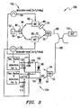
- FIGURE 3 is a block diagram that schematically illustrates an apparatus for determining chromatic dispersion, polarization dependent dispersion and other optical properties of an optical device in which light is reflected from a device under test according to another embodiment of the present invention.
- the apparatus is generally designated by reference number 150, and comprises transmitter portion 152 and receiver portion 154.
- Transmitter portion 152 and receiver portion 154 are substantially identical to transmitter and receiver portions 45 and 50 in the embodiment illustrated in FIGURE 2, and like reference numbers are used to identify like components of the portions.
- Apparatus 150 in FIGURE 3 differs from apparatus 40 in FIGURE 2 in that optical input signal 80 in FIGURE 3 is passed to and reflected from DUT 170 to provide optical output signal 180 (the terms “optical input signal” and “optical output signal” as used herein are intended to refer to signals to and from an optical DUT irrespective of the manner in which the optical input signal interacts with the DUT).
- the output from the comparator comprises four distinct phase shift and amplitude measurements 120, 122, 124 and 126, from which the chromatic and polarization dependent dispersion of DUT 170 can be readily determined as a function of wavelength as laser source 52 is tuned to different wavelengths.
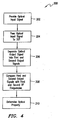
- FIGURE 4 is a flow chart that illustrates steps of a method for determining chromatic and polarization dependent dispersion and other optical properties of an optical device according to an embodiment of the present invention.
- the method is generally designated by reference number 200, and begins by providing an optical input signal having first and second signal components that are modulated at first and second frequencies, respectively, and that have first and second polarization states, respectively (step 202).
- the optical input signal is then passed to an optical DUT (step 204).
- An optical output signal from the optical DUT is then separated into first and second optical output signals having third and fourth polarization states which may be the same as or different from the first and second polarization states, and the first and second optical output signals are converted to first and second RF output signals, respectively (step 206).
- Each of the first and second RF output signals are then compared with reference signals at the first and second RF frequencies to provide four phase shift and amplitude measurements (step 208).
- the four phase shift and amplitude measurements as a function of wavelength are then used to determine optical properties of the DUT (step 210).
- the invention can be varied in many respects without departing therefrom.
- the invention is primarily directed to determining chromatic dispersion and polarization mode dispersion of an optical device
- the invention can also determine other optical properties of an optical device. Exemplary of such other optical properties include insertion loss, transmittance, reflectance, polarization dependent loss, polarization dependent reflectance, group delay and differential group delay.
- the DUT comprises a length of optical fiber
- the DUT can comprise any device that propagates, reflects or otherwise interacts with optical signals.
Landscapes
- Physics & Mathematics (AREA)
- Chemical & Material Sciences (AREA)
- Optics & Photonics (AREA)
- Analytical Chemistry (AREA)
- General Physics & Mathematics (AREA)
- Dispersion Chemistry (AREA)
- Optical Communication System (AREA)
- Testing Of Optical Devices Or Fibers (AREA)
Abstract
Description
Claims (10)
- A method for determining at least one optical property of an optical device (82,170) comprising:providing an optical input signal (80) that includes first and second signal components (66, 72) that are modulated at first and second frequencies, respectively, and that have first and second polarization states, respectively;passing the optical input signal (80) to an optical device (82,170);separating an optical signal (90,180) from the optical device (82,170) into first and second output signals (94,96) that have third and fourth polarization states, respectively; andcomparing each of said first and second output signals (94,96) with reference signals at said first and second frequencies to provide four phase shift and amplitude measurements (120,122,124,126) from which the at least one optical property of the optical device (82,170) can be determined as a function of wavelength of the optical input signal (80).
- The method according to claim 1, wherein said step of providing an optical input signal (80) includes:splitting an optical signal (54) into first and second optical signals (56,58); andmodulating said first and second optical signals (56,58) at first and second frequencies, respectively, to provide first and second modulated optical signals (66,72).
- The method according to claim 2, wherein said step of providing an optical input signal (80) further includes adjusting the polarization of said first and second modulated optical signals (66,72) to be substantially orthogonal to provide first and second modulated optical signals (66,72) that have first and second substantially orthogonal polarization states, respectively, and combining said first and second modulated optical signal (66,72) having said first and second substantially orthogonal polarization states to provide said optical input signal (80).
- The method according to one of claims 1 to 3, wherein said separating step includes separating said optical signal (90,180) from the optical device (82,170) into first and second optical output signals (94,96) that have the third and fourth substantially orthogonal polarization states, respectively, and converting said first and second optical output signals (94,96) to first and second RF output signals (102,104), respectively, and wherein said comparing step comprises comparing each of said first and second RF output signals (102,104) with reference signals at first and second RF frequencies.
- The method according to one of claims 1 to 4, wherein said at least one optical property includes, at least one of chromatic dispersion, polarization dependent dispersion, insertion loss, transmittance, reflectance, polarization dependent loss, polarization dependent reflectance, group delay and differential group delay.
- The method according to one of claims 1 to 5, wherein said passing step comprises either passing said optical input signal (80) through said optical device (82), or reflecting said optical input signal (80) from said optical device (170).
- The method according to one of claims 1 to 6, wherein said optical input signal (80) is provided by a tunable optical source (52) for controlling wavelength of the optical input signal (80); and wherein said chromatic dispersion and said polarization dependent dispersion is determined as a function of the wavelength as said optical input signal (80) is tuned to different wavelengths.
- Apparatus for determining at least one optical property of an optical device (82,170), comprising:a transmitter (45,152) capable of providing an optical input signal (80) to an optical device (82,170), said optical input signal (80) including first and second signal components (66,72) that are modulated at first and second frequencies, respectively, and that have first and second polarization states, respectively; anda receiver (50,154) capable of receiving an optical output signal (90,180) from the optical device (82,170), said receiver (50,154) including a converter (98,100) for converting the optical output signal (90,180) from the optical device (82,170) into first and second output signals (102,104) corresponding to third and fourth polarization states, respectively, and a comparator (106,108,110,112) for comparing each of the first and second output signals (102,104) with reference signals at said first and second frequencies to provide four phase shift and amplitude measurements (120,122,124, 126) from which the at least one optical property of the optical device (82,170) can be determined as a function of wavelength.
- The apparatus according to claim 8, wherein said transmitter (45,152) includes:a tunable optical source (52);a splitter (60) for splitting an optical signal (54) from said tunable optical source (52) into first and second optical signals (56,58);first and second modulators (62,68) for modulating said first and second optical signals (56,58) at first and second RF frequencies, respectively, to provide first and second modulated optical signals (66,72);a device (74) for adjusting the polarization of said first and second modulated optical signals (66,72) to have first and second substantially orthogonal polarization states, respectively; anda combiner (76) for combining said first and second modulated optical signals (66,72) having said first and second substantially orthogonal polarization states to provide said optical input signal (80); and wherein said receiver (50,154) comprises:a separator (92) for separating said optical output signal (90,180) into first and second optical output signals (94,96) that have the third and fourth substantially orthogonal polarization states, respectively; andsaid converter (98,100) converts said first and second optical output signals (94,96) to first and second RF output signals (102,104) that correspond to the third and fourth substantially orthogonal polarization states, respectively, wherein said comparator (106,108,110,112) compares each of said first and second RF output signals (102,104) with reference signals at said first and second RF frequencies to provide said four phase shift and amplitude measurements (120,122,124,126).
- The apparatus according to claim 9, wherein said comparator (106,108,110,112) comprises a plurality of RF mixers (106,108,110,112).
Applications Claiming Priority (2)
| Application Number | Priority Date | Filing Date | Title |
|---|---|---|---|
| US10/211,018 US6724468B2 (en) | 2002-07-31 | 2002-07-31 | Single sweep phase shift method and apparatus for measuring chromatic and polarization dependent dispersion |
| US211018 | 2002-07-31 |
Publications (3)
| Publication Number | Publication Date |
|---|---|
| EP1387158A2 true EP1387158A2 (en) | 2004-02-04 |
| EP1387158A3 EP1387158A3 (en) | 2005-06-08 |
| EP1387158B1 EP1387158B1 (en) | 2007-03-07 |
Family
ID=30115247
Family Applications (1)
| Application Number | Title | Priority Date | Filing Date |
|---|---|---|---|
| EP03008476A Expired - Lifetime EP1387158B1 (en) | 2002-07-31 | 2003-04-11 | Single sweep phase shift method and apparatus for measuring chromatic and polarization dependent dispersion |
Country Status (3)
| Country | Link |
|---|---|
| US (1) | US6724468B2 (en) |
| EP (1) | EP1387158B1 (en) |
| DE (1) | DE60312266T2 (en) |
Cited By (2)
| Publication number | Priority date | Publication date | Assignee | Title |
|---|---|---|---|---|
| EP1628121A1 (en) * | 2004-08-18 | 2006-02-22 | Agilent Technologies Inc | Determination of polarization dependent properties |
| EP1562032A3 (en) * | 2004-02-05 | 2009-01-14 | Agilent Technologies, Inc. | Heterodyne optical network analysis that utilizes signal modulation |
Families Citing this family (9)
| Publication number | Priority date | Publication date | Assignee | Title |
|---|---|---|---|---|
| US7072039B2 (en) * | 2003-08-20 | 2006-07-04 | Itt Manufacturing Enterprises, Inc. | Active multiple-color imaging polarimetry |
| JP2006243311A (en) * | 2005-03-03 | 2006-09-14 | Fuji Photo Film Co Ltd | Analysis method and analysis apparatus for optical characteristic of optical medium, and production monitor method |
| US20080062407A1 (en) * | 2006-08-31 | 2008-03-13 | Mikhail Boroditsky | Method and apparatus for increasing the security of the physical fiber plant by polarization monitoring |
| US8111386B2 (en) * | 2008-01-22 | 2012-02-07 | Ofs Fitel, Llc | Measuring modal content of multi-moded fibers |
| TWI394969B (en) * | 2009-10-30 | 2013-05-01 | Wistron Neweb Corp | Test system |
| US10821542B2 (en) * | 2013-03-15 | 2020-11-03 | Mks Instruments, Inc. | Pulse synchronization by monitoring power in another frequency band |
| US9964585B1 (en) * | 2015-11-13 | 2018-05-08 | Anritsu Company | Exact phase synchronization of a remote receiver with a measurement instrument |
| US10003453B1 (en) * | 2015-11-13 | 2018-06-19 | Anritsu Company | Phase synchronization of measuring instruments using free space transmission |
| US11243141B2 (en) * | 2018-09-21 | 2022-02-08 | National Institute Of Standards | Method and apparatus for chromatic dispersion measurement based on optoelectronic oscillations |
Family Cites Families (15)
| Publication number | Priority date | Publication date | Assignee | Title |
|---|---|---|---|---|
| US5258615A (en) * | 1990-08-03 | 1993-11-02 | Gpt Limited | Optical fiber monitoring by detection of polarization variations |
| US5486919A (en) * | 1992-04-27 | 1996-01-23 | Canon Kabushiki Kaisha | Inspection method and apparatus for inspecting a particle, if any, on a substrate having a pattern |
| US5654793A (en) * | 1995-05-19 | 1997-08-05 | Barlow; Arthur John | Method and apparatus for high resolution measurement of very low levels of polarization mode dispersion (PMD) in single mode optical fibers and for calibration of PMD measuring instruments |
| JP3131144B2 (en) * | 1996-03-29 | 2001-01-31 | 株式会社アドバンテスト | Polarization mode dispersion measurement device |
| IT1291413B1 (en) * | 1997-02-13 | 1999-01-11 | Andrea Galtarossa | REFLECTOMETRIC INSTRUMENT FOR THE MEASUREMENT OF BIRIFRANGENCE DISTRIBUTED IN SINGLE-MODE FIBER OPTICS |
| JP3394902B2 (en) * | 1998-02-20 | 2003-04-07 | アンリツ株式会社 | Chromatic dispersion measuring device and polarization dispersion measuring device |
| JP2000019068A (en) * | 1998-06-30 | 2000-01-21 | Fujitsu Ltd | Apparatus and method for measuring chromatic dispersion |
| US6144450A (en) * | 1999-09-13 | 2000-11-07 | Lucent Technologies | Apparatus and method for improving the accuracy of polarization mode dispersion measurements |
| US6459830B1 (en) * | 2000-02-08 | 2002-10-01 | Sprint Communications Company L.P. | Method and apparatus to compensate for polarization mode dispersion |
| US6519027B1 (en) * | 2000-03-08 | 2003-02-11 | Lucent Technologies Inc. | Polarization mode dispersion measurement |
| JP4493808B2 (en) * | 2000-07-10 | 2010-06-30 | 株式会社アドバンテスト | Optical characteristic measuring apparatus, method, and recording medium |
| JP4004720B2 (en) * | 2000-08-09 | 2007-11-07 | 富士通株式会社 | Chromatic dispersion measuring apparatus and method |
| JP2002122514A (en) * | 2000-10-13 | 2002-04-26 | Advantest Corp | Optical property measuring device, method, recording medium |
| EP1207377A3 (en) * | 2000-11-17 | 2007-03-28 | Agilent Technologies, Inc. | Method and apparatus for measuring optical properties by means of the Jones matrix |
| US6943891B2 (en) * | 2002-03-15 | 2005-09-13 | Agilent Technologies, Inc. | Determining optical characteristics of optical devices under test |
-
2002
- 2002-07-31 US US10/211,018 patent/US6724468B2/en not_active Expired - Fee Related
-
2003
- 2003-04-11 EP EP03008476A patent/EP1387158B1/en not_active Expired - Lifetime
- 2003-04-11 DE DE60312266T patent/DE60312266T2/en not_active Expired - Fee Related
Cited By (2)
| Publication number | Priority date | Publication date | Assignee | Title |
|---|---|---|---|---|
| EP1562032A3 (en) * | 2004-02-05 | 2009-01-14 | Agilent Technologies, Inc. | Heterodyne optical network analysis that utilizes signal modulation |
| EP1628121A1 (en) * | 2004-08-18 | 2006-02-22 | Agilent Technologies Inc | Determination of polarization dependent properties |
Also Published As
| Publication number | Publication date |
|---|---|
| DE60312266T2 (en) | 2007-11-08 |
| DE60312266D1 (en) | 2007-04-19 |
| US6724468B2 (en) | 2004-04-20 |
| EP1387158B1 (en) | 2007-03-07 |
| EP1387158A3 (en) | 2005-06-08 |
| US20040021864A1 (en) | 2004-02-05 |
Similar Documents
| Publication | Publication Date | Title |
|---|---|---|
| US5982530A (en) | Apparatus for driving an optical modulator to measure, and compensate for, dispersion in an optical transmission line | |
| US5406368A (en) | Method and apparatus for chromatic dispersion measurements | |
| US5717489A (en) | Polarization mode dispersion measuring instrument and method | |
| US10241003B2 (en) | Method of measuring time delays with respect to differential mode delay (DMD) of a multi-mode fiber (MMF) or a few-mode fiber (FMF) | |
| JPH04215B2 (en) | ||
| US6724468B2 (en) | Single sweep phase shift method and apparatus for measuring chromatic and polarization dependent dispersion | |
| US6122086A (en) | Compensation of dispersion | |
| EP1562032A2 (en) | Heterodyne optical network analysis that utilizes signal modulation | |
| US20180241498A1 (en) | Optical fiber polarization multiplexing | |
| US6671038B2 (en) | Measurement of polarization dependent characteristic of optical components | |
| US7006207B2 (en) | Polarization mode dispersion measuring device, method, recording medium | |
| JPH07294381A (en) | A method for determining the zero-dispersion wavelength of an optical waveguide. | |
| US7253906B2 (en) | Polarization state frequency multiplexing | |
| US4918491A (en) | Emission spectral width measuring apparatus for light source | |
| JPH0354292B2 (en) | ||
| JP3384322B2 (en) | Chromatic dispersion measuring method and chromatic dispersion measuring device | |
| US6813027B2 (en) | Time difference synchronization for determination of a property of an optical device | |
| GB2350184A (en) | Apparatus and method to measure wavelength | |
| JPH11271179A (en) | Optical fiber chromatic dispersion measuring device | |
| JPH0622189Y2 (en) | Optical spectrum measuring device | |
| JPH0620987Y2 (en) | Optical spectrum measuring device | |
| US20050121633A1 (en) | Determination of optical properties of a device under test in both directions in transmission and in reflection | |
| JP2001091408A (en) | Polarization mode dispersion measurement and zero dispersion wavelength measurement equipment | |
| JPS613024A (en) | Apparatus for measuring wavelength dispersion of optical fiber | |
| Madsen et al. | A novel optical vector spectrum analysis technique |
Legal Events
| Date | Code | Title | Description |
|---|---|---|---|
| PUAI | Public reference made under article 153(3) epc to a published international application that has entered the european phase |
Free format text: ORIGINAL CODE: 0009012 |
|
| AK | Designated contracting states |
Kind code of ref document: A2 Designated state(s): AT BE BG CH CY CZ DE DK EE ES FI FR GB GR HU IE IT LI LU MC NL PT RO SE SI SK TR |
|
| AX | Request for extension of the european patent |
Extension state: AL LT LV MK |
|
| PUAL | Search report despatched |
Free format text: ORIGINAL CODE: 0009013 |
|
| AK | Designated contracting states |
Kind code of ref document: A3 Designated state(s): AT BE BG CH CY CZ DE DK EE ES FI FR GB GR HU IE IT LI LU MC NL PT RO SE SI SK TR |
|
| AX | Request for extension of the european patent |
Extension state: AL LT LV MK |
|
| 17P | Request for examination filed |
Effective date: 20050722 |
|
| AKX | Designation fees paid |
Designated state(s): DE FR GB |
|
| GRAP | Despatch of communication of intention to grant a patent |
Free format text: ORIGINAL CODE: EPIDOSNIGR1 |
|
| RAP1 | Party data changed (applicant data changed or rights of an application transferred) |
Owner name: AGILENT TECHNOLOGIES, INC. |
|
| GRAS | Grant fee paid |
Free format text: ORIGINAL CODE: EPIDOSNIGR3 |
|
| GRAA | (expected) grant |
Free format text: ORIGINAL CODE: 0009210 |
|
| AK | Designated contracting states |
Kind code of ref document: B1 Designated state(s): DE FR GB |
|
| REG | Reference to a national code |
Ref country code: GB Ref legal event code: FG4D |
|
| REF | Corresponds to: |
Ref document number: 60312266 Country of ref document: DE Date of ref document: 20070419 Kind code of ref document: P |
|
| PGFP | Annual fee paid to national office [announced via postgrant information from national office to epo] |
Ref country code: DE Payment date: 20070531 Year of fee payment: 5 |
|
| ET | Fr: translation filed | ||
| PGFP | Annual fee paid to national office [announced via postgrant information from national office to epo] |
Ref country code: GB Payment date: 20070425 Year of fee payment: 5 |
|
| PLBE | No opposition filed within time limit |
Free format text: ORIGINAL CODE: 0009261 |
|
| STAA | Information on the status of an ep patent application or granted ep patent |
Free format text: STATUS: NO OPPOSITION FILED WITHIN TIME LIMIT |
|
| 26N | No opposition filed |
Effective date: 20071210 |
|
| PGFP | Annual fee paid to national office [announced via postgrant information from national office to epo] |
Ref country code: FR Payment date: 20070517 Year of fee payment: 5 |
|
| GBPC | Gb: european patent ceased through non-payment of renewal fee |
Effective date: 20080411 |
|
| PG25 | Lapsed in a contracting state [announced via postgrant information from national office to epo] |
Ref country code: DE Free format text: LAPSE BECAUSE OF NON-PAYMENT OF DUE FEES Effective date: 20081101 |
|
| REG | Reference to a national code |
Ref country code: FR Ref legal event code: ST Effective date: 20081231 |
|
| PG25 | Lapsed in a contracting state [announced via postgrant information from national office to epo] |
Ref country code: FR Free format text: LAPSE BECAUSE OF NON-PAYMENT OF DUE FEES Effective date: 20080430 |
|
| PG25 | Lapsed in a contracting state [announced via postgrant information from national office to epo] |
Ref country code: GB Free format text: LAPSE BECAUSE OF NON-PAYMENT OF DUE FEES Effective date: 20080411 |