EP1387118A2 - Hose with a wrapped layer - Google Patents
Hose with a wrapped layer Download PDFInfo
- Publication number
- EP1387118A2 EP1387118A2 EP03015633A EP03015633A EP1387118A2 EP 1387118 A2 EP1387118 A2 EP 1387118A2 EP 03015633 A EP03015633 A EP 03015633A EP 03015633 A EP03015633 A EP 03015633A EP 1387118 A2 EP1387118 A2 EP 1387118A2
- Authority
- EP
- European Patent Office
- Prior art keywords
- layer
- hose
- wrapped
- film
- article
- Prior art date
- Legal status (The legal status is an assumption and is not a legal conclusion. Google has not performed a legal analysis and makes no representation as to the accuracy of the status listed.)
- Withdrawn
Links
Images
Classifications
-
- F—MECHANICAL ENGINEERING; LIGHTING; HEATING; WEAPONS; BLASTING
- F16—ENGINEERING ELEMENTS AND UNITS; GENERAL MEASURES FOR PRODUCING AND MAINTAINING EFFECTIVE FUNCTIONING OF MACHINES OR INSTALLATIONS; THERMAL INSULATION IN GENERAL
- F16L—PIPES; JOINTS OR FITTINGS FOR PIPES; SUPPORTS FOR PIPES, CABLES OR PROTECTIVE TUBING; MEANS FOR THERMAL INSULATION IN GENERAL
- F16L11/00—Hoses, i.e. flexible pipes
- F16L11/04—Hoses, i.e. flexible pipes made of rubber or flexible plastics
- F16L11/08—Hoses, i.e. flexible pipes made of rubber or flexible plastics with reinforcements embedded in the wall
- F16L11/085—Hoses, i.e. flexible pipes made of rubber or flexible plastics with reinforcements embedded in the wall comprising one or more braided layers
-
- Y—GENERAL TAGGING OF NEW TECHNOLOGICAL DEVELOPMENTS; GENERAL TAGGING OF CROSS-SECTIONAL TECHNOLOGIES SPANNING OVER SEVERAL SECTIONS OF THE IPC; TECHNICAL SUBJECTS COVERED BY FORMER USPC CROSS-REFERENCE ART COLLECTIONS [XRACs] AND DIGESTS
- Y10—TECHNICAL SUBJECTS COVERED BY FORMER USPC
- Y10T—TECHNICAL SUBJECTS COVERED BY FORMER US CLASSIFICATION
- Y10T428/00—Stock material or miscellaneous articles
- Y10T428/13—Hollow or container type article [e.g., tube, vase, etc.]
- Y10T428/1352—Polymer or resin containing [i.e., natural or synthetic]
- Y10T428/1369—Fiber or fibers wound around each other or into a self-sustaining shape [e.g., yarn, braid, fibers shaped around a core, etc.]
-
- Y—GENERAL TAGGING OF NEW TECHNOLOGICAL DEVELOPMENTS; GENERAL TAGGING OF CROSS-SECTIONAL TECHNOLOGIES SPANNING OVER SEVERAL SECTIONS OF THE IPC; TECHNICAL SUBJECTS COVERED BY FORMER USPC CROSS-REFERENCE ART COLLECTIONS [XRACs] AND DIGESTS
- Y10—TECHNICAL SUBJECTS COVERED BY FORMER USPC
- Y10T—TECHNICAL SUBJECTS COVERED BY FORMER US CLASSIFICATION
- Y10T428/00—Stock material or miscellaneous articles
- Y10T428/13—Hollow or container type article [e.g., tube, vase, etc.]
- Y10T428/1352—Polymer or resin containing [i.e., natural or synthetic]
- Y10T428/139—Open-ended, self-supporting conduit, cylinder, or tube-type article
- Y10T428/1393—Multilayer [continuous layer]
Definitions
- the present invention relates to an improved hose for use in motor vehicles, and more particularly to a hose for use in the air-conditioning (AC) and refrigeration systems.
- AC air-conditioning
- Multi-layer hoses are known to be used in the AC systems and refrigeration system in both stationary and mobile applications.
- An innermost portion is in direct contact with the fluid to be transported through the hose.
- an outermost layer is a protective covering.
- One or more layers located between the innermost and outermost layers provide desired reinforcement, strength, or other operational properties to the hose.
- a primary consideration when selecting a material or a construction method for an AC hose is the permeability of the hose. Since AC efficiency over time is based in part on the retention of refrigerant, loss of the refrigerant by permeation through the hose should be avoided. In addition, the effect of refrigerants on the environment has lately come under scrutiny such that refrigerant releases should be minimized to the greatest extent possible.
- the inventors have recognized a need for a AC hose with a high resistance to permeation that can also be manufactured through the elimination of at least one expensive processing step.
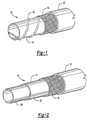
- a hose 10 includes an outermost layer 12 and a wrapped layer 14 that is the innermost portion of hose 10. This type of hose is called a veneer hose.
- Hose 10 may include a reinforcement layer 16 between outermost layer 12 and wrapped layer 14.
- Wrapped layer 14 has a spiral format that results from the wrapping process.
- the spiral format has a seam 18 that forms a helix around the longitudinal axis of the hose.
- the material of the wrapped layer overlaps itself at seam 18.
- the overlap in the wrapped layer ensures a seam which is less susceptible to leaking.
- the innermost portion includes wrapped layer 14' as well as an inner tube 20, where the wrapped layer surrounds the inner tube.
- This type of hose is called a barrier hose.
- Wrapped layer 14' has a longitudinal format that results from the wrapping process.
- the longitudinal format has a seam 22 that is parallel to the longitudinal axis of the hose.
- the material of the wrapped layer overlaps itself at seam 22.
- the overlap in the wrapped layer ensures a seam which is less susceptible to leaking.
- additional components may be utilized, such as insulation, binding or adhesive layers.
- additional layers may be located between any two other layers.
- the material of the outermost layer may have any composition that suitably protects the remaining layers of the hose from physical damage such as abrasion or cut-through.
- the outermost layer may be applied by any known manufacturing method, including extrusion.
- the material of the outermost layer is an elastomeric material.
- Preferred elastomeric materials include those that have enhanced resistance to the environmental conditions present when the hose is in use. For example, in motor vehicle, elastomeric materials with enhanced resistance to heat and ozone are preferred.
- the reinforcement layer includes textile yarn, fabric, cord, plastic or metal wire and combinations thereof.
- the reinforcement layer includes a braided textile yarn because the material provides a good strength to cost ratio, while also utilizing inexpensive braiding apparatuses.
- the material of the inner tube may be any elastomeric material.
- the purpose of the inner tube is to facilitate the attachment of coupling devices to the finished hose.
- the inner tube may be constructed by any known process, including extrusion.
- the material of the wrapped layer may have any composition.
- the material of the wrapped layer is resistant to refrigerant permeation, thus creating a permeation resistant layer in the hose.
- One suitable class of materials includes thermoplastics such as polyamides, polyethylene naphthalate (PEN), or ethylene vinyl alcohol polymer (EVOH).
- PEN polyethylene naphthalate
- EVOH ethylene vinyl alcohol polymer
- a polyamide such as nylon is the most preferred material for the wrapped layer.
- the material of the wrapped layer is in the form of a film. Any width or thickness of film may be used and the film may be kept on a bobbin or other suitable device.
- a binding layer may be utilized to help secure the wrapped layer.
- the binding layer surrounds the wrapped layer.
- the binding layer may either surround the inner tube or the wrapped layer. In either aspect, the binding layer is in contact with the wrapped layer. Any suitable material which serves to help secure the wrapped layer in position may be utilized as a binding layer.
- the binding layer is a material that, upon heating or curing, will bond to the wrapped layer.
- a elastomeric material is used in the binding layer.
- the hose of the present invention is manufactured as generally described below.
- a conventional hose making mandrel is provided, around which the wrapped layer material is wrapped.
- the binding layer and/or adhesive may be applied.
- a reinforcing layer is applied using a conventional apparatus.
- the outermost layer is applied over the reinforcing layer. After construction of the hose, it may cured through the application of heat or other curing conditions.
- a mandrel is provided, around which an inner tube is placed.
- the wrapping layer material is wrapped.
- the binding layer may be applied next.
- a reinforcing layer and a outermost layer may be applied. Finally, the hose is cured.
- Conventional processes and apparatus may be used to construct the barrier, binding, reinforcing and/or outermost layers.
- a braider may be used to apply the reinforcing layer
- an extruder may be used to apply the outermost layer.
- a calendaring or skimming apparatus may be used to apply the binding layer.
- Construction of the wrapped layer may be accomplished using known processes and apparatus that have not previously been utilized for the wrapping of an innermost portion. Even though conventional processes and apparatuses are utilized, the elimination of even one extrusion step is cost effective. In addition, the elimination of extrusion allows the manufacture of hoses with a inner diameter of greater than 3/4" that include a permeation resistant layer.
- the wrapping process may result in either of two formats for the wrapped layer: a spiral wrap or a longitudinal wrap, as seen respectively in FIG. 1 and 2.
- the longitudinal wrap is preferred because the apparatuses and processes require less complex machinery and thus is least expensive to manufacture.
- the wrapped layer may include a butted seam, i.e., no overlap, although an overlap seam is preferred because of increased resistance to permeation.
- conventional processes and apparatus may be used to apply adhesive to the seam and/or the exterior of the wrapped layer, before, during or after the wrapping step.
- Hoses according to the present invention were constructed to determine their permeation characteristics. Two 16 mm barrier hoses were manufactured by wrapping nylon film around an inner tube. In the first hose, a 1 mil nylon film was utilized while in the second hose a 5 mil nylon film was utilized. The resultant hoses were 0.4 m in length and were filled with R-134a refrigerant to a density of approximately 0.6 g/cm 3 . The filled hoses were tested according to SAE Standard J2064; that is, stored for two weeks at a temperature of 80°C. The permeation rate for the 1 mil wrapped nylon hose was calculated to be 1.51 g/m/day, which corresponds to 4.087 kg/m 2 /year.
- the permeation rate for the 5 mil wrapped nylon hose was calculated to be 0.73 g/m/day, which corresponds to 1.976 kg/m 2 /year. Both of these permeation rates are well below the acceptable maximum rate of 9.7 kg/m 2 /year outlined in SAE Standard J2064.
- the hoses were physically inspected for signs of blistering, particularly at the seams. Blistering is a symptom of pooling of refrigerant and could lead to hose failure. No signs of blistering were apparent on the test hoses.
- test hoses were subjected to an explosive decompression test to mimic catastrophic failure due to a vehicle accident.
- a hose passes the explosive decompression test through the absence of delamination. Both hoses did not show any signs of delamination after testing.
- Hoses constructed with at least one wrapped layer achieve acceptable permeation rates at a significant reduction in manufacturing cost.
- the elimination of even one extruder from the hose manufacturing process makes the hose more economical because a large capital expenditure is eliminated, as are the associated machinery operating costs.
Landscapes
- Engineering & Computer Science (AREA)
- General Engineering & Computer Science (AREA)
- Mechanical Engineering (AREA)
- Rigid Pipes And Flexible Pipes (AREA)
- Extrusion Moulding Of Plastics Or The Like (AREA)
Abstract
Description
Claims (20)
- An article of manufacture, comprising:wherein said innermost portion comprises a wrapped layer.a tubular innermost portion,at least one reinforcing layer surrounding said innermost portion, andan outermost layer surrounding said reinforcing layer,
- The article of claim 1, wherein the innermost portion consists of said wrapped layer.
- The article of claim 1, wherein the innermost portion comprises said wrapped layer surrounding an inner tube.
- The article of claim 1, wherein said wrapped layer has a longitudinal format with an overlap seam.
- The article of claim 1, wherein said wrapped layer has a spiral format with an overlap seam.
- The article of claim 1, wherein said wrapped layer comprises a nylon film.
- The article of claim 1, further comprising a binding layer in contact with said wrapped layer.
- The article of claim 1, wherein said reinforcing layer includes a braided textile yarn or metal wire.
- A method of manufacturing a hose, comprising:wrapping a layer of film around an article selected from the group consisting of a mandrel and an inner tube;surrounding said layer of film with a reinforcing layer, andsurrounding said reinforcing layer with an outermost layer.
- The method of claim 9, wherein said film is a nylon film.
- The method of claim 9, further comprising applying a binding layer in contact with said layer of film.
- The method of claim 9, wherein said surrounding said layer of film step includes:braiding a textile yarn around said layer of film.
- The method of claim 9, wherein said surrounding said reinforcing step includes:extruding an elastomeric material around said reinforcing layer.
- The method of claim 9, further comprising, prior to said wrapping step, extruding said inner tube.
- The method of claim 9, wherein said wrapping step consists of wrapping said layer of film around said mandrel.
- The method of claim 9, wherein said wrapping step comprises wrapping said layer of film around said inner tube.
- The method of claim 9, further comprising curing said hose.
- A method of manufacturing a hose, comprising:wrapping a layer of thermoplastic material around an article selected from a group consisting of a mandrel and an inner tube;braiding a reinforcing material around said elastomeric material;extruding an elastomeric material around said reinforcing material
- The method of claim 18, wherein the thermoplastic material is a nylon.
- The method of claim 18, wherein the reinforcing material is a textile yarn or a metal wire.
Applications Claiming Priority (2)
| Application Number | Priority Date | Filing Date | Title |
|---|---|---|---|
| US10/209,511 US20040022979A1 (en) | 2002-07-31 | 2002-07-31 | Hose with a wrapped layer |
| US209511 | 2002-07-31 |
Publications (2)
| Publication Number | Publication Date |
|---|---|
| EP1387118A2 true EP1387118A2 (en) | 2004-02-04 |
| EP1387118A3 EP1387118A3 (en) | 2004-03-31 |
Family
ID=30115224
Family Applications (1)
| Application Number | Title | Priority Date | Filing Date |
|---|---|---|---|
| EP03015633A Withdrawn EP1387118A3 (en) | 2002-07-31 | 2003-07-16 | Hose with a wrapped layer |
Country Status (2)
| Country | Link |
|---|---|
| US (1) | US20040022979A1 (en) |
| EP (1) | EP1387118A3 (en) |
Families Citing this family (2)
| Publication number | Priority date | Publication date | Assignee | Title |
|---|---|---|---|---|
| US8944112B2 (en) | 2007-02-01 | 2015-02-03 | Eaton Corporation | Braided hose and method of making same |
| US20190046446A1 (en) * | 2016-09-30 | 2019-02-14 | Eriochem Usa, Llc | Apo-e modified lipid nanoparticles for drug delivery to targeted tissues and therapeutic methods |
Family Cites Families (13)
| Publication number | Priority date | Publication date | Assignee | Title |
|---|---|---|---|---|
| US2800145A (en) * | 1953-05-12 | 1957-07-23 | Resistoflex Corp | Barrier hose and hose assembly |
| US3886980A (en) * | 1973-05-21 | 1975-06-03 | Acme Hamilton Mfg | Steam hose design |
| ES241999Y (en) * | 1978-03-14 | 1979-12-16 | A PIPE TO TRANSPORT CRUDE OIL. | |
| US4758455A (en) * | 1985-07-10 | 1988-07-19 | Handy & Harman Automotive Group Inc. | Composite fuel and vapor tube having increased heat resistance |
| US4679600A (en) * | 1985-09-09 | 1987-07-14 | Durodyne, Inc. | High tensile strength removable hose covering |
| US4706712A (en) * | 1986-03-27 | 1987-11-17 | Dayco Products, Inc. | Hose construction |
| US5052444A (en) * | 1987-04-30 | 1991-10-01 | The Fluorocarbon Company | Reinforced fluid hose having on-bonded tape |
| FR2674934B1 (en) * | 1991-04-05 | 1993-08-20 | Caoutchouc Manuf Plastique | PROCESS FOR THE CONTINUOUS PRODUCTION OF A FLEXIBLE TUBULAR STRUCTURE COMPRISING A MULTILAYER SHEET OF INCORPORATED MICROMETRIC THICKNESS AND FLEXIBLE TUBULAR STRUCTURES PRODUCED ACCORDING TO THIS PROCESS. |
| US5302428A (en) * | 1992-09-29 | 1994-04-12 | Shaw Industries Ltd. | Multi-layer wraparound heat shrink sleeve |
| FR2732441B1 (en) * | 1995-03-29 | 1997-05-30 | Coflexip | FLEXIBLE TUBULAR PIPE WITH POLYMERIC INTERNAL SEALING SHEATH |
| WO1997024543A1 (en) * | 1996-01-03 | 1997-07-10 | Flexfab Horizons International, Inc. | Lightweight hose with a helically-wound reinforcing member and method for making the same |
| ES2178467T3 (en) * | 1998-08-13 | 2002-12-16 | Trinova Aeroquip Gmbh | HOLLOW BODY IN THE FORM OF A FLEXIBLE BAR. |
| KR20030082578A (en) * | 2001-01-30 | 2003-10-22 | 파커-한니핀 코포레이션 | Thermoplastic reinforced hose construction and method of making the same |
-
2002
- 2002-07-31 US US10/209,511 patent/US20040022979A1/en not_active Abandoned
-
2003
- 2003-07-16 EP EP03015633A patent/EP1387118A3/en not_active Withdrawn
Also Published As
| Publication number | Publication date |
|---|---|
| EP1387118A3 (en) | 2004-03-31 |
| US20040022979A1 (en) | 2004-02-05 |
Similar Documents
| Publication | Publication Date | Title |
|---|---|---|
| CA1290710C (en) | Reinforced hose | |
| US4510974A (en) | Fluid conveying hose | |
| EP1020673B1 (en) | Hose for transporting carbon dioxide refrigerant | |
| US7517563B2 (en) | Hose of impermeability and a process for manufacturing the same | |
| US6345647B2 (en) | Fluid-impermeable composite hose | |
| EP2043856B1 (en) | Method of manufacture of a high pressure barrier hose | |
| CN1134743A (en) | Tubes for High Pressure Fluids | |
| US3310447A (en) | Composite tubing method of manufacture | |
| EP1356226B1 (en) | Thermoplastic reinforced hose construction | |
| US4341578A (en) | Method of hose production | |
| US7017616B2 (en) | Reinforced hose | |
| US6071579A (en) | Laminated air brake tubing | |
| US5156699A (en) | Process for producing a hybrid flexible hose | |
| JP2004216665A (en) | High pressure low gas permeable hose | |
| US20060204697A1 (en) | Reinforced, high pressure, low permeation multilayer hose | |
| JP2000018440A (en) | Hose for transporting carbon dioxide refrigerant | |
| US20040022979A1 (en) | Hose with a wrapped layer | |
| GB2034433A (en) | Method of hose production and product | |
| JP2001235068A (en) | Low-permeability hose and method of manufacturing the same | |
| US20030145896A1 (en) | Coiled laminated air brake tubing | |
| JPH1038151A (en) | Multi-layer hose | |
| MX2008010028A (en) | Brake hose. | |
| KR101410609B1 (en) | High pressur Gas Hose | |
| US20240209965A1 (en) | Reinforced thermoplastic pipes | |
| JP2025510994A (en) | Hybrid tube for industrial and fluid hose products and manufacturing method thereof |
Legal Events
| Date | Code | Title | Description |
|---|---|---|---|
| PUAI | Public reference made under article 153(3) epc to a published international application that has entered the european phase |
Free format text: ORIGINAL CODE: 0009012 |
|
| AK | Designated contracting states |
Kind code of ref document: A2 Designated state(s): AT BE BG CH CY CZ DE DK EE ES FI FR GB GR HU IE IT LI LU MC NL PT RO SE SI SK TR |
|
| AX | Request for extension of the european patent |
Extension state: AL LT LV MK |
|
| PUAL | Search report despatched |
Free format text: ORIGINAL CODE: 0009013 |
|
| RIC1 | Information provided on ipc code assigned before grant |
Ipc: 7F 16L 9/17 B Ipc: 7B 29C 47/02 B Ipc: 7F 16L 11/08 A |
|
| AK | Designated contracting states |
Kind code of ref document: A3 Designated state(s): AT BE BG CH CY CZ DE DK EE ES FI FR GB GR HU IE IT LI LU MC NL PT RO SE SI SK TR |
|
| AX | Request for extension of the european patent |
Extension state: AL LT LV MK |
|
| STAA | Information on the status of an ep patent application or granted ep patent |
Free format text: STATUS: THE APPLICATION HAS BEEN WITHDRAWN |
|
| 18W | Application withdrawn |
Effective date: 20040705 |