EP1387085B1 - Piston pump for viscous materials - Google Patents
Piston pump for viscous materials Download PDFInfo
- Publication number
- EP1387085B1 EP1387085B1 EP03017276A EP03017276A EP1387085B1 EP 1387085 B1 EP1387085 B1 EP 1387085B1 EP 03017276 A EP03017276 A EP 03017276A EP 03017276 A EP03017276 A EP 03017276A EP 1387085 B1 EP1387085 B1 EP 1387085B1
- Authority
- EP
- European Patent Office
- Prior art keywords
- piston
- recited
- pump
- pressure chamber
- piston rod
- Prior art date
- Legal status (The legal status is an assumption and is not a legal conclusion. Google has not performed a legal analysis and makes no representation as to the accuracy of the status listed.)
- Expired - Lifetime
Links
- 239000011345 viscous material Substances 0.000 title 1
- 238000007598 dipping method Methods 0.000 claims description 18
- 239000007921 spray Substances 0.000 claims description 11
- 238000005192 partition Methods 0.000 claims description 8
- 239000012530 fluid Substances 0.000 claims description 4
- 238000007789 sealing Methods 0.000 claims description 3
- 230000033001 locomotion Effects 0.000 description 10
- 238000006073 displacement reaction Methods 0.000 description 7
- 238000012423 maintenance Methods 0.000 description 1
- 238000004519 manufacturing process Methods 0.000 description 1
Images


Classifications
-
- F—MECHANICAL ENGINEERING; LIGHTING; HEATING; WEAPONS; BLASTING
- F04—POSITIVE - DISPLACEMENT MACHINES FOR LIQUIDS; PUMPS FOR LIQUIDS OR ELASTIC FLUIDS
- F04B—POSITIVE-DISPLACEMENT MACHINES FOR LIQUIDS; PUMPS
- F04B5/00—Machines or pumps with differential-surface pistons
-
- F—MECHANICAL ENGINEERING; LIGHTING; HEATING; WEAPONS; BLASTING
- F04—POSITIVE - DISPLACEMENT MACHINES FOR LIQUIDS; PUMPS FOR LIQUIDS OR ELASTIC FLUIDS
- F04B—POSITIVE-DISPLACEMENT MACHINES FOR LIQUIDS; PUMPS
- F04B15/00—Pumps adapted to handle specific fluids, e.g. by selection of specific materials for pumps or pump parts
- F04B15/02—Pumps adapted to handle specific fluids, e.g. by selection of specific materials for pumps or pump parts the fluids being viscous or non-homogeneous
-
- F—MECHANICAL ENGINEERING; LIGHTING; HEATING; WEAPONS; BLASTING
- F04—POSITIVE - DISPLACEMENT MACHINES FOR LIQUIDS; PUMPS FOR LIQUIDS OR ELASTIC FLUIDS
- F04B—POSITIVE-DISPLACEMENT MACHINES FOR LIQUIDS; PUMPS
- F04B23/00—Pumping installations or systems
- F04B23/02—Pumping installations or systems having reservoirs
- F04B23/021—Pumping installations or systems having reservoirs the pump being immersed in the reservoir
- F04B23/023—Pumping installations or systems having reservoirs the pump being immersed in the reservoir only the pump-part being immersed, the driving-part being outside the reservoir
-
- F—MECHANICAL ENGINEERING; LIGHTING; HEATING; WEAPONS; BLASTING
- F04—POSITIVE - DISPLACEMENT MACHINES FOR LIQUIDS; PUMPS FOR LIQUIDS OR ELASTIC FLUIDS
- F04B—POSITIVE-DISPLACEMENT MACHINES FOR LIQUIDS; PUMPS
- F04B23/00—Pumping installations or systems
- F04B23/04—Combinations of two or more pumps
- F04B23/06—Combinations of two or more pumps the pumps being all of reciprocating positive-displacement type
-
- F—MECHANICAL ENGINEERING; LIGHTING; HEATING; WEAPONS; BLASTING
- F04—POSITIVE - DISPLACEMENT MACHINES FOR LIQUIDS; PUMPS FOR LIQUIDS OR ELASTIC FLUIDS
- F04B—POSITIVE-DISPLACEMENT MACHINES FOR LIQUIDS; PUMPS
- F04B53/00—Component parts, details or accessories not provided for in, or of interest apart from, groups F04B1/00 - F04B23/00 or F04B39/00 - F04B47/00
- F04B53/10—Valves; Arrangement of valves
- F04B53/12—Valves; Arrangement of valves arranged in or on pistons
- F04B53/125—Reciprocating valves
- F04B53/127—Disc valves
- F04B53/128—Annular disc valves
Definitions
- the invention relates to a piston pump, in particular for transporting highly viscous media from a storage reservoir to an implement, for example a spray gun, having a differential piston disposed in a cylindrical housing and translationally drivable, whose first pressure chamber is connectable alternately with the second chamber via a check valve inserted into a connecting line, and with the supply reservoir via an inlet valve inserted into a transport line.
- the inlet valve sometimes does not close the first pressure chamber reliably during a displacement motion in the direction of the inlet valve, so that medium is pushed back into the storage reservoir. Bit it is particularly disadvantageous that when viscous media are processed, the first pressure chamber is often not completely filled during an intake stroke. As a result, the flow to the implement is not constant, and brief interruptions occur, so that the delivery flow may possibly break off an/or layers of varying thickness may be applied. Air pockets may also form in the medium, which have an undesirable effect on the processing of the medium.
- the object of the invention is therefore to design a piston pump in such a way that the first pressure chamber of the differential piston is always completely filled with the medium to be processed, so that a continuous stream of spray and uniform application of the medium to be processed are ensured.
- Production cost of the piston pump should be kept at a minimum, yet uniformly good processing even of highly viscous media should be made possible for a long period of time.
- the differential piston is provided with a dipping piston that is immersed in the medium to be transported, attached to an aligned, protruding piston rod; that the pass-through for the piston rod from the first pressure chamber is tightly sealed by one or more, preferably stretchable, seals; and that the transport line in the area of the pass-through for the piston rod is offset to the side or positioned concentrically to the latter.
- the pass-through for the piston rod and segments of the transport line in a connecting piece that is joined with the differential piston housing, and on which an extension piece that receives the dipping piston is mounted diametrically opposite the housing, where the inlet valve that is upline from the first pressure chamber should be located in the connecting piece and should consist of a ball placed in a flow-through cage, able to move against the force of a spring, and a valve seat in the form of a ring.
- the pass-through for the piston rod may be provided in an internal partition of the housing, and the transport line may be formed in this area by cutouts made in the internal partition, preferably bored holes, running concentrically to the pass-through.
- the inlet valve that is upline from the first pressure chamber of the differential piston may be formed here simply by means of a sealing ring associated with the openings in the internal partition of the housing, and a pressure spring acting on it, braced against the housing.
- the dipping piston may be made of a disk positioned in the extension piece with radial play and having openings which are solidly attached to the piston rod, a stop provided on the piston rod at a distance from the disk, and a cover disk movably mounted between the stop and the disk, by which the openings in the disk may optionally be covered.
- Constructing a piston pump according to the invention guarantees that the flow delivered to the implement will not be interrupted, in spite of the reversals of the displacement motions of the differential piston; instead, the dipping piston and the design of the volumes and of the inlet valve positioned in the offset transport line ensure that the two pressure chambers are always completely filled with the medium that is to be processed. Due to the force of the spring acting on the movable part of the inlet valve which is not affected by the piston rod and the dipping piston, the inlet valve closes automatically as soon as there is no longer negative pressure in the first pressure chamber; as a result, backflow is no longer possible.
- the space vacated by the ejection of the medium to be processed from the second pressure chamber is thus immediately filled when the differential piston is moved in the direction of the inlet valve. Furthermore, because of the differently dimensioned effective faces of the differential piston, medium continues to be ejected. Therefore no interruption of the transport stream needs to be accepted, nor can air pockets form.
- the drawing shows an exemplary embodiment of the differential piston pump constructed according to the invention, which is explained in detail below.
- the figures show the following, all in axial sectional views:
- differential piston pump 1 serves to transport a medium contained in a storage reservoir 2 to an implement in the form of a spray gun 3.
- differential piston pump 1 is connected with spray gun 3 through a line 4, and consists of a differential piston 12 placed in a housing 11, whose first pressure chamber 13 is connected to second pressure chamber 14 through a connecting line 15, into which a check valve 16 is inserted.
- second pressure chamber 14 With the help of seals 17 under load from springs 18, second pressure chamber 14 is sealed toward the outside; with the help of additional seals 19, on which a spring 20 also acts, second pressure chamber 14 is sealed toward first pressure chamber 13.
- the medium to be processed is fed to first pressure chamber 13 through a transport line 22, whose segments 22' and 22" are provided in a connecting piece 21.
- Connecting piece 21 is attached to housing 11 of differential piston 12, or housing 11 is screwed into connecting piece 21.
- Inserted into transport line 22 between segments 22' and 22" is an inlet valve 23, consisting of a valve body in the form of a ball 25, and a ring 26 as the valve seat.
- Ball 25 is held in a cage 24 formed by crossbars, and these are acted on by a spring 27 inserted into a plug 28 screwed into connecting piece 21.
- Segments 22' and 22" of transport line 22 are closed by additional plugs 29 and 29'.
- connecting piece 21 Also mounted on connecting piece 21 is an extension piece 30, which makes up part of transport line 22, and in which a dipping piston 41 is positioned and axially movable.
- a piston rod 31 is firmly connected with differential piston 12 by means of a connecting piece 36 through which fluid can flow, which is provided with openings 37 for that purpose.
- Pass-through 32 of piston rod 31 from first pressure chamber 13 of housing 11 into extension piece 30 is closed fluid-tight by means of a seal 34 inserted into a sleeve 33.
- a nut 35 screwed into connecting piece 21 acts on seal 34.
- Dipping piston 41 has a disk 42 solidly connected to piston rod 31, which is inserted into extension piece 30 with radial play, and which is provided with openings 43.
- a stop 44 in the form of a ring is attached to piston rod 31 at a distance from disk 42, and positioned between stop 44 and disk 42 is a disk 45, which is movably mounted on piston rod 31 and by which the openings 43 of disk 42 may optionally be covered.
- differential piston pump 1 When differential piston pump 1 is started up, in accordance with the operating position shown in Figure 1, with the help of dipping piston 41, which is immersed in the medium in storage reservoir 2, the medium above dipping piston 41 is raised, since the openings 43 of disk 42 are covered by disk 45, and is pressed through the opening inlet valve 23 into first pressure chamber 13 of differential piston 12. From there the medium flows with the first or second stroke through connecting line 15 into check valve 16, which also opens, and into second pressure chamber 14.
- spray gun 3 may be actuated in order to apply the medium to a part.
- the medium is transported out of second pressure chamber 14 into line 4 and thus to spray gun 3.
- Check valve 16 is closed at this time.
- inlet valve 23 open, medium is brought from storage reservoir 2 into first pressure chamber 13 by dipping piston 41.
- the volumes of the two pressure chambers 13 and 14 here are matched to each other in such a way, for example in the proportions 2 : 1, that second pressure chamber 14 is guaranteed to always be filled. Surplus medium can always flow back into storage reservoir 2 during both displacement motions of dipping piston 41, since the latter's disk 42 is inserted into extension piece 30 with radial play and has a number of openings 43.
- first pressure chamber 13 and segment 22' of transport line 22 are filled with medium, but the upward motion of the dipping piston is not yet finished, the medium flows back into storage reservoir 2 because of the radial play of dipping piston 41; during the downward motion dipping piston 41 can readily dip into the medium in storage reservoir 2, since disk 45 is raised off of disk 42.
- transport line 22 is arranged concentrically to pass-through 32 of piston rod 31.
- housing 11' is provided with an internal partition 51, in which the seals 34 and the nuts 35 that act on them are held or supported by sleeve 33, which is screwed into it.
- a number of openings 52 in the form of bored holes are made in the internal partition 51 concentric to pass-through 32; these produce the connection of transport line 22 with first pressure chamber 13.
- an inlet valve 53 which consists in this case of a sealing ring 54 and a pressure spring 55 acting on it, which is braced against a projection 56 that protrudes inward from housing 11'.
- inlet valve 53 is open.
- inlet valve 53 is closed in accordance with the operating position according to Figure 2.
Landscapes
- Engineering & Computer Science (AREA)
- Mechanical Engineering (AREA)
- General Engineering & Computer Science (AREA)
- Details Of Reciprocating Pumps (AREA)
- Reciprocating Pumps (AREA)
- Nozzles (AREA)
Description
- The invention relates to a piston pump, in particular for transporting highly viscous media from a storage reservoir to an implement, for example a spray gun, having a differential piston disposed in a cylindrical housing and translationally drivable, whose first pressure chamber is connectable alternately with the second chamber via a check valve inserted into a connecting line, and with the supply reservoir via an inlet valve inserted into a transport line.
- In a piston pump of this type manufactured by J. Wagner GmbH, Markdorf, Germany, under the designation HC 12000G, there is an inlet valve upline from the differential piston having a ball as its valve gate, which is opened during a suction motion of the differential piston, so that the medium to be processed is drawn into the first pressure chamber. At the same time, the medium located in the second pressure chamber is fed to the implement, and the second pressure chamber is filled again by medium flowing from the first pressure chamber. Thus continuous transport is provided during both displacement motions of the differential piston.
- An other piston pump is disclosed in US 3,330,217 which shows the same technical principal of Wagner's piston pump HC 12000G.
- Although operating pressures up to 230 bar can be produced with this piston pump, the inlet valve sometimes does not close the first pressure chamber reliably during a displacement motion in the direction of the inlet valve, so that medium is pushed back into the storage reservoir. Bit it is particularly disadvantageous that when viscous media are processed, the first pressure chamber is often not completely filled during an intake stroke. As a result, the flow to the implement is not constant, and brief interruptions occur, so that the delivery flow may possibly break off an/or layers of varying thickness may be applied. Air pockets may also form in the medium, which have an undesirable effect on the processing of the medium.
- The object of the invention is therefore to design a piston pump in such a way that the first pressure chamber of the differential piston is always completely filled with the medium to be processed, so that a continuous stream of spray and uniform application of the medium to be processed are ensured. In addition, there should be assurance that no air pockets are formed, and that a high operating pressure is maintainable even with long feed lines. Production cost of the piston pump should be kept at a minimum, yet uniformly good processing even of highly viscous media should be made possible for a long period of time.
- This is accomplished according to the invention with a piston pump, as described herein, by the fact that the differential piston is provided with a dipping piston that is immersed in the medium to be transported, attached to an aligned, protruding piston rod; that the pass-through for the piston rod from the first pressure chamber is tightly sealed by one or more, preferably stretchable, seals; and that the transport line in the area of the pass-through for the piston rod is offset to the side or positioned concentrically to the latter.
- It is preferable here to provide the pass-through for the piston rod and segments of the transport line in a connecting piece that is joined with the differential piston housing, and on which an extension piece that receives the dipping piston is mounted diametrically opposite the housing, where the inlet valve that is upline from the first pressure chamber should be located in the connecting piece and should consist of a ball placed in a flow-through cage, able to move against the force of a spring, and a valve seat in the form of a ring. In an alternate design, the pass-through for the piston rod may be provided in an internal partition of the housing, and the transport line may be formed in this area by cutouts made in the internal partition, preferably bored holes, running concentrically to the pass-through.
- The inlet valve that is upline from the first pressure chamber of the differential piston may be formed here simply by means of a sealing ring associated with the openings in the internal partition of the housing, and a pressure spring acting on it, braced against the housing.
- In a simple design, the dipping piston may be made of a disk positioned in the extension piece with radial play and having openings which are solidly attached to the piston rod, a stop provided on the piston rod at a distance from the disk, and a cover disk movably mounted between the stop and the disk, by which the openings in the disk may optionally be covered.
- It is also advisable to attach the piston rod to the differential piston by using a connecting piece through which fluid can flow attached to the latter, and to design the volume of the first pressure chamber of the differential piston to be about 1.2 to 2.5 times as large as the volume of the second pressure chamber.
- Constructing a piston pump according to the invention guarantees that the flow delivered to the implement will not be interrupted, in spite of the reversals of the displacement motions of the differential piston; instead, the dipping piston and the design of the volumes and of the inlet valve positioned in the offset transport line ensure that the two pressure chambers are always completely filled with the medium that is to be processed. Due to the force of the spring acting on the movable part of the inlet valve which is not affected by the piston rod and the dipping piston, the inlet valve closes automatically as soon as there is no longer negative pressure in the first pressure chamber; as a result, backflow is no longer possible. The space vacated by the ejection of the medium to be processed from the second pressure chamber is thus immediately filled when the differential piston is moved in the direction of the inlet valve. Furthermore, because of the differently dimensioned effective faces of the differential piston, medium continues to be ejected. Therefore no interruption of the transport stream needs to be accepted, nor can air pockets form.
- Thus, with minimal cost, the operating behavior of a differential piston pump working under high pressure is significantly improved; in addition, a long, problem-free operating life with simple maintenance is provided.
- The drawing shows an exemplary embodiment of the differential piston pump constructed according to the invention, which is explained in detail below. The figures show the following, all in axial sectional views:
-
- Figure 1:
- the differential piston pump with attached spray gun as implement, at the beginning of an upward stroke of the differential piston.
- Figure 2:
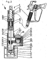
- the differential piston pump according to Figure 1, after reversal of the displacement motion of the differential piston.
- Figure 3:
- a different type of design of the transport line fitted with an inlet valve, in the operating position according to Figure 1.
- Figure 4:
- the different type of design of the transport line fitted with an inlet valve of Figure 3, in the operating position according to Figure 2.
- The differential piston pump shown in Figures 1 and 2, and designated in each case as 1, serves to transport a medium contained in a
storage reservoir 2 to an implement in the form of a spray gun 3. In this casedifferential piston pump 1 is connected with spray gun 3 through aline 4, and consists of adifferential piston 12 placed in ahousing 11, whosefirst pressure chamber 13 is connected tosecond pressure chamber 14 through a connectingline 15, into which acheck valve 16 is inserted. With the help ofseals 17 under load fromsprings 18,second pressure chamber 14 is sealed toward the outside; with the help ofadditional seals 19, on which aspring 20 also acts,second pressure chamber 14 is sealed towardfirst pressure chamber 13. - The medium to be processed is fed to
first pressure chamber 13 through atransport line 22, whosesegments 22' and 22" are provided in a connectingpiece 21. Connectingpiece 21 is attached tohousing 11 ofdifferential piston 12, orhousing 11 is screwed into connectingpiece 21. Inserted intotransport line 22 betweensegments 22' and 22" is aninlet valve 23, consisting of a valve body in the form of aball 25, and aring 26 as the valve seat.Ball 25 is held in acage 24 formed by crossbars, and these are acted on by aspring 27 inserted into aplug 28 screwed into connectingpiece 21.Segments 22' and 22" oftransport line 22 are closed byadditional plugs 29 and 29'. - Also mounted on connecting
piece 21 is anextension piece 30, which makes up part oftransport line 22, and in which adipping piston 41 is positioned and axially movable. To accomplish this, apiston rod 31 is firmly connected withdifferential piston 12 by means of a connectingpiece 36 through which fluid can flow, which is provided withopenings 37 for that purpose. Pass-through 32 ofpiston rod 31 fromfirst pressure chamber 13 ofhousing 11 intoextension piece 30 is closed fluid-tight by means of aseal 34 inserted into asleeve 33. To this end, anut 35 screwed into connectingpiece 21 acts onseal 34. - Dipping
piston 41 has adisk 42 solidly connected topiston rod 31, which is inserted intoextension piece 30 with radial play, and which is provided withopenings 43. In addition, astop 44 in the form of a ring is attached topiston rod 31 at a distance fromdisk 42, and positioned betweenstop 44 anddisk 42 is adisk 45, which is movably mounted onpiston rod 31 and by which theopenings 43 ofdisk 42 may optionally be covered. - When
differential piston pump 1 is started up, in accordance with the operating position shown in Figure 1, with the help of dippingpiston 41, which is immersed in the medium instorage reservoir 2, the medium above dippingpiston 41 is raised, since theopenings 43 ofdisk 42 are covered bydisk 45, and is pressed through the openinginlet valve 23 intofirst pressure chamber 13 ofdifferential piston 12. From there the medium flows with the first or second stroke through connectingline 15 intocheck valve 16, which also opens, and intosecond pressure chamber 14. - If the two
pressure chambers differential piston 12, when spray gun 3 is open, the medium is transported out ofsecond pressure chamber 14 intoline 4 and thus to spray gun 3.Check valve 16 is closed at this time. At the same time, withinlet valve 23 open, medium is brought fromstorage reservoir 2 intofirst pressure chamber 13 by dippingpiston 41. - On the other hand, when the displacement motion of
differential piston 12 is reversed, and hence during a downward stroke, withinlet valve 23 closed and checkvalve 16 open, the medium that is insecond pressure chamber 14 is pushed intoline 4 and thus flows to spray gun 3. In addition, withinlet valve 23 closed medium flows fromfirst pressure chamber 13 intosecond pressure chamber 14, so that the latter becomes filled and transporting is ensured without interruption, in spite of the translational displacement motions ofdifferential piston 12. Accordingly, spray gun 3 is continuously supplied with the medium to be processed. - The volumes of the two
pressure chambers second pressure chamber 14 is guaranteed to always be filled. Surplus medium can always flow back intostorage reservoir 2 during both displacement motions of dippingpiston 41, since the latter'sdisk 42 is inserted intoextension piece 30 with radial play and has a number ofopenings 43. - If
first pressure chamber 13 and segment 22' oftransport line 22 are filled with medium, but the upward motion of the dipping piston is not yet finished, the medium flows back intostorage reservoir 2 because of the radial play of dippingpiston 41; during the downwardmotion dipping piston 41 can readily dip into the medium instorage reservoir 2, sincedisk 45 is raised off ofdisk 42. - In the variant embodiments portrayed in Figures 3 and 4,
transport line 22 is arranged concentrically to pass-through 32 ofpiston rod 31. To this end, housing 11' is provided with aninternal partition 51, in which theseals 34 and the nuts 35 that act on them are held or supported bysleeve 33, which is screwed into it. In addition, a number ofopenings 52 in the form of bored holes are made in theinternal partition 51 concentric to pass-through 32; these produce the connection oftransport line 22 withfirst pressure chamber 13. - To seal
openings 52, aninlet valve 53 is provided, which consists in this case of a sealingring 54 and apressure spring 55 acting on it, which is braced against aprojection 56 that protrudes inward from housing 11'. In Figure 3, which corresponds to the operating position ofdifferential pump 1 according to Figure 1,inlet valve 53 is open. In Figure 4, in contrast,inlet valve 53 is closed in accordance with the operating position according to Figure 2.
Claims (13)
- A piston pump (1) for transporting highly viscous media from a storage reservoir (2) to a spray gun (3), the pump having a differential piston (12) positioned in a cylindrical housing (11) and translationally drivable, the pump having a first pressure chamber (13) connected to a second pressure chamber (14) via a connecting line (15) having a check valve (16) therein, the pump further connected with a storage reservoir via an inlet valve (23;53),
characterized by the differential piston (12) having a dipping piston (41) that dips into the medium to be transported, the dipping piston attached to an aligned, protruding piston rod (31),
wherein a pass-through (32) of the piston rod (31) from the first pressure chamber (13) is closed fluid-tight by at least one seal (33),
and having a transport line (22) in the vicinity of the pass-through (32) of the piston rod (31). - The piston pump as recited in Claim 1,
characterized in that the transport line (22) is positioned, at least in part, concentric to the piston rod (31). - The piston pump as recited in Claim 1,
characterized in that the transport line (22) is, at least in part, laterally offset from the piston rod (31). - The piston pump as recited in one of the preceding claims,
characterized by the fact that the pass-through (32) of the piston rod (31) has at least a portion of the transport line (22) provided in a connecting piece (21) connected with the housing (11) of the differential piston (12), and wherein an extension piece (30) receives the dipping piston (41) and is attached to the connecting piece (21). - The piston pump as recited in Claim 4,
characterized by the inlet valve (23) being located upline from the first pressure chamber (13). - The piston pump as recited in claim 5 wherein the first pressure chamber (13) is in the connecting piece (21).
- The piston pump as recited in one of the preceding claims wherein the inlet valve (23) includes a ball (25) received in a cage (24) through which fluid can flow and in which the ball (25) is urged by a spring (24) towards a valve seat.
- The piston pump as recited in one of the preceding claims,
characterized by the fact that the pass-through (32) of the piston rod (31) is provided in an internal partition (51) of the housing (11), and that the transport line (22) is formed in this area by a plurality of openings (52) in the internal partition (51), located concentric to the pass-through (32). - The piston pump recited in Claim 8,
characterized by the fact that the inlet valve (23) is formed by a sealing ring (54) associated with the openings (52) in the internal partition (51) of the housing (11), and
a pressure spring (55) acting between the ring and the housing (11). - The piston pump as recited in one of the preceding claims,
wherein the dipping piston (41) includes:a. a disk (42) having openings (43) therein and positioned in the extension piece (30) and attached to the piston rod (31),b. a stop (44) provided on the piston rod (31) at a distance from the disk (42), andc. a cover (45) mounted on the piston rod (31) and movable between the stop (44) and the disk (42)such that the openings (43) provided in the disk (42) are closed when the cover (45) is proximate the disk (42) and the openings (43) are open when the cover (45) is distal of the disk (42). - The piston pump as recited in Claim 10,
wherein the disk (42) has radial play with respect to the extension piece (30). - The piston pump as recited in one of the preceding claims,
wherein the piston rod (31) is attached to the differential piston (12) by a connecting piece (26) though which fluid can flow and which is attached to the differential piston (12). - The piston pump as recited in one of the preceding claims,
characterized by the fact that the first pressure chamber (13) has a volume of about 1.2 to 2.5 times a volume of the second pressure chamber (14).
Applications Claiming Priority (2)
| Application Number | Priority Date | Filing Date | Title |
|---|---|---|---|
| DE10235140A DE10235140B4 (en) | 2002-08-01 | 2002-08-01 | piston pump |
| DE10235140 | 2002-08-01 |
Publications (3)
| Publication Number | Publication Date |
|---|---|
| EP1387085A2 EP1387085A2 (en) | 2004-02-04 |
| EP1387085A3 EP1387085A3 (en) | 2004-10-27 |
| EP1387085B1 true EP1387085B1 (en) | 2006-05-17 |
Family
ID=30010551
Family Applications (1)
| Application Number | Title | Priority Date | Filing Date |
|---|---|---|---|
| EP03017276A Expired - Lifetime EP1387085B1 (en) | 2002-08-01 | 2003-07-30 | Piston pump for viscous materials |
Country Status (4)
| Country | Link |
|---|---|
| US (1) | US7137792B2 (en) |
| EP (1) | EP1387085B1 (en) |
| DE (1) | DE10235140B4 (en) |
| ES (1) | ES2261830T3 (en) |
Families Citing this family (12)
| Publication number | Priority date | Publication date | Assignee | Title |
|---|---|---|---|---|
| EP1874483A4 (en) * | 2004-10-15 | 2008-09-03 | California Blue Llc | SPRÜHBRÄUNE-discharge |
| US20060140791A1 (en) * | 2004-12-29 | 2006-06-29 | Deming Glenn I | Miniature rotary compressor, and methods related thereto |
| US8845222B2 (en) | 2005-10-24 | 2014-09-30 | Wagner Spray Tech Corporation | Modular paint pump for a paint roller |
| FR2916659B1 (en) * | 2007-06-04 | 2011-04-08 | Jjb Diffusion | DEVICE FOR APPLYING OR PROJECTING A MATERIAL OF HIGH DENSITY. |
| DE102008005319A1 (en) * | 2008-01-21 | 2009-07-23 | Seneca S.A. | Device for separating drinking water fraction from sea water, has piston coupled to pushing-/traction element that is rotatably supported in eccentric, and valve control comprising control element that is movable by traction element |
| CN105377445B (en) * | 2013-07-19 | 2018-03-27 | 固瑞克明尼苏达有限公司 | Multi-point sealing part lubricating system |
| DE102015000410A1 (en) * | 2015-01-14 | 2016-07-14 | Ralf Müller | System for pumping highly viscous and solid masses from containers |
| CN104989615B (en) * | 2015-06-08 | 2017-01-25 | 东莞市联洲知识产权运营管理有限公司 | Quantitative glue pumping pump device for viscous liquid |
| CN105034263B (en) * | 2015-08-21 | 2017-11-10 | 胡妹芳 | A kind of simple connection air-cylinder type high viscosity liquid takes out adhesive dispenser |
| CN105034259B (en) * | 2015-08-21 | 2017-11-07 | 重庆淬智机械有限公司 | A kind of motor-driven high viscosity liquid takes out adhesive dispenser |
| DE102016002263A1 (en) | 2016-02-25 | 2017-08-31 | Pressol - Schmiergeräte GmbH | Conveying device for conveying a flowable medium |
| US11950677B2 (en) | 2019-02-28 | 2024-04-09 | L'oreal | Devices and methods for electrostatic application of cosmetics |
Family Cites Families (17)
| Publication number | Priority date | Publication date | Assignee | Title |
|---|---|---|---|---|
| US1065709A (en) * | 1911-06-21 | 1913-06-24 | F E Myers And Brother | Pump. |
| US1543087A (en) * | 1923-03-24 | 1925-06-23 | John A Baker | Well pump |
| US2281899A (en) * | 1939-03-30 | 1942-05-05 | Phillips Petroleum Co | Well equipment |
| US2730957A (en) * | 1949-04-16 | 1956-01-17 | Union Carbide & Carbon Corp | Apparatus for pumping a volatile liquid |
| US2841086A (en) * | 1953-05-13 | 1958-07-01 | Nat Supply Co | Downwell pump |
| US3164102A (en) * | 1962-07-16 | 1965-01-05 | Benjamin F Schmidt | Oil well pump |
| US3330217A (en) | 1965-07-20 | 1967-07-11 | Binks Mfg Co | Pump |
| US3827339A (en) * | 1969-03-21 | 1974-08-06 | Nordson Corp | Double acting hydraulic pump |
| DE6922324U (en) | 1969-06-04 | 1969-10-16 | Speidel & Keller Kg | SPRING MANOMETER FOR MEASURING BLOOD PRESSURE. |
| US4087209A (en) | 1975-12-05 | 1978-05-02 | Aluterv Aluminiumipari Tervezo Vallalat | Displacement slurry pump |
| DE3710172A1 (en) * | 1987-03-27 | 1988-10-13 | Hilger & Kern Gmbh | DEVICE FOR REMOVING AND PRECISELY DOSING MEDIA |
| US5080565A (en) * | 1991-01-04 | 1992-01-14 | Tecumseh Products Company | Retainer for piston head subassembly and method of retaining piston head subassembly |
| US5228842A (en) | 1991-07-30 | 1993-07-20 | Wagner Spray Tech Corporation | Quick-change fluid section for piston-type paint pumps |
| GB9318736D0 (en) | 1993-09-09 | 1993-10-27 | Elopak Systems | Apparatus and methods |
| WO1999066206A1 (en) * | 1998-06-17 | 1999-12-23 | Robert Bosch Gmbh | Filter system in the intake chamber of a piston pump |
| US6193476B1 (en) * | 1999-09-13 | 2001-02-27 | Gerald T. Sweeney | 1½ Piston force pump |
| US6193482B1 (en) * | 1999-10-22 | 2001-02-27 | Chih-Ming Chen | Structure of a piston of an air-filing device |
-
2002
- 2002-08-01 DE DE10235140A patent/DE10235140B4/en not_active Expired - Fee Related
-
2003
- 2003-07-29 US US10/629,317 patent/US7137792B2/en not_active Expired - Lifetime
- 2003-07-30 EP EP03017276A patent/EP1387085B1/en not_active Expired - Lifetime
- 2003-07-30 ES ES03017276T patent/ES2261830T3/en not_active Expired - Lifetime
Also Published As
| Publication number | Publication date |
|---|---|
| US20040050961A1 (en) | 2004-03-18 |
| DE10235140B4 (en) | 2005-02-17 |
| ES2261830T3 (en) | 2006-11-16 |
| EP1387085A3 (en) | 2004-10-27 |
| EP1387085A2 (en) | 2004-02-04 |
| DE10235140A1 (en) | 2004-02-12 |
| US7137792B2 (en) | 2006-11-21 |
Similar Documents
| Publication | Publication Date | Title |
|---|---|---|
| US7137792B2 (en) | Piston pump for high viscous materials | |
| JP4088738B2 (en) | Fuel injection pump | |
| US8444401B2 (en) | Check valve and piston pump having check valve | |
| JPH094560A (en) | Cryogen pump | |
| US5800136A (en) | Pump with bypass valve | |
| JP2002533612A (en) | Piston pump for high pressure fuel formation | |
| DE19919908B4 (en) | Diaphragm pump with an inlet opening controlled by the diaphragm | |
| US10900473B2 (en) | Conveying device for conveying a flowable medium | |
| JPS5912185A (en) | Double-acting reciprocating pump | |
| EP1869321A2 (en) | Liquid additive injection pump with mixing chamber and one way valve | |
| KR102070512B1 (en) | Automatic distribution grease feeding apparatus | |
| CN103470416A (en) | Radial plunger piston oil supplying pump applied to high-pressure common-rail fuel oil injection system | |
| US5310323A (en) | Plunger pump | |
| JPH08284805A (en) | Axial piston type hydraulic rotary machine | |
| US3771908A (en) | Apparatus and process for pumping gluey material | |
| KR101772734B1 (en) | Pulsation swash plate type piston pump having the function of preventing | |
| JPH01247770A (en) | Slurry pump | |
| KR200272412Y1 (en) | Automatic grrase pourer | |
| JP4343972B2 (en) | Mist injection device | |
| CN222478869U (en) | Pneumatic metering pump | |
| KR100397071B1 (en) | Automatic grrase pourer | |
| JP3561226B2 (en) | Multiple pump unit | |
| JPS6241073B2 (en) | ||
| FI118055B (en) | Piston engine injection pump | |
| US4846308A (en) | Liquid feed pump system |
Legal Events
| Date | Code | Title | Description |
|---|---|---|---|
| PUAI | Public reference made under article 153(3) epc to a published international application that has entered the european phase |
Free format text: ORIGINAL CODE: 0009012 |
|
| AK | Designated contracting states |
Kind code of ref document: A2 Designated state(s): AT BE BG CH CY CZ DE DK EE ES FI FR GB GR HU IE IT LI LU MC NL PT RO SE SI SK TR |
|
| AX | Request for extension of the european patent |
Extension state: AL LT LV MK |
|
| PUAL | Search report despatched |
Free format text: ORIGINAL CODE: 0009013 |
|
| AK | Designated contracting states |
Kind code of ref document: A3 Designated state(s): AT BE BG CH CY CZ DE DK EE ES FI FR GB GR HU IE IT LI LU MC NL PT RO SE SI SK TR |
|
| AX | Request for extension of the european patent |
Extension state: AL LT LV MK |
|
| RIC1 | Information provided on ipc code assigned before grant |
Ipc: 7F 04B 5/00 B Ipc: 7F 04B 9/14 A Ipc: 7F 04B 23/02 B Ipc: 7F 04B 15/02 B |
|
| 17P | Request for examination filed |
Effective date: 20050330 |
|
| AKX | Designation fees paid |
Designated state(s): ES FR GB IT |
|
| REG | Reference to a national code |
Ref country code: DE Ref legal event code: 8566 |
|
| GRAP | Despatch of communication of intention to grant a patent |
Free format text: ORIGINAL CODE: EPIDOSNIGR1 |
|
| GRAS | Grant fee paid |
Free format text: ORIGINAL CODE: EPIDOSNIGR3 |
|
| GRAA | (expected) grant |
Free format text: ORIGINAL CODE: 0009210 |
|
| AK | Designated contracting states |
Kind code of ref document: B1 Designated state(s): ES FR GB IT |
|
| REG | Reference to a national code |
Ref country code: GB Ref legal event code: FG4D |
|
| REG | Reference to a national code |
Ref country code: ES Ref legal event code: FG2A Ref document number: 2261830 Country of ref document: ES Kind code of ref document: T3 |
|
| ET | Fr: translation filed | ||
| PLBE | No opposition filed within time limit |
Free format text: ORIGINAL CODE: 0009261 |
|
| STAA | Information on the status of an ep patent application or granted ep patent |
Free format text: STATUS: NO OPPOSITION FILED WITHIN TIME LIMIT |
|
| 26N | No opposition filed |
Effective date: 20070220 |
|
| PGFP | Annual fee paid to national office [announced via postgrant information from national office to epo] |
Ref country code: FR Payment date: 20140730 Year of fee payment: 12 Ref country code: ES Payment date: 20140730 Year of fee payment: 12 Ref country code: GB Payment date: 20140730 Year of fee payment: 12 |
|
| PGFP | Annual fee paid to national office [announced via postgrant information from national office to epo] |
Ref country code: IT Payment date: 20140730 Year of fee payment: 12 |
|
| GBPC | Gb: european patent ceased through non-payment of renewal fee |
Effective date: 20150730 |
|
| PG25 | Lapsed in a contracting state [announced via postgrant information from national office to epo] |
Ref country code: GB Free format text: LAPSE BECAUSE OF NON-PAYMENT OF DUE FEES Effective date: 20150730 Ref country code: IT Free format text: LAPSE BECAUSE OF NON-PAYMENT OF DUE FEES Effective date: 20150730 |
|
| REG | Reference to a national code |
Ref country code: FR Ref legal event code: ST Effective date: 20160331 |
|
| PG25 | Lapsed in a contracting state [announced via postgrant information from national office to epo] |
Ref country code: FR Free format text: LAPSE BECAUSE OF NON-PAYMENT OF DUE FEES Effective date: 20150731 |
|
| PG25 | Lapsed in a contracting state [announced via postgrant information from national office to epo] |
Ref country code: ES Free format text: LAPSE BECAUSE OF NON-PAYMENT OF DUE FEES Effective date: 20150731 |
|
| REG | Reference to a national code |
Ref country code: ES Ref legal event code: FD2A Effective date: 20180704 |