EP1386758A1 - Pneumatic tire - Google Patents
Pneumatic tire Download PDFInfo
- Publication number
- EP1386758A1 EP1386758A1 EP02780776A EP02780776A EP1386758A1 EP 1386758 A1 EP1386758 A1 EP 1386758A1 EP 02780776 A EP02780776 A EP 02780776A EP 02780776 A EP02780776 A EP 02780776A EP 1386758 A1 EP1386758 A1 EP 1386758A1
- Authority
- EP
- European Patent Office
- Prior art keywords
- tire
- block
- highland
- lowland
- denotes
- Prior art date
- Legal status (The legal status is an assumption and is not a legal conclusion. Google has not performed a legal analysis and makes no representation as to the accuracy of the status listed.)
- Granted
Links
Images











Classifications
-
- B—PERFORMING OPERATIONS; TRANSPORTING
- B60—VEHICLES IN GENERAL
- B60C—VEHICLE TYRES; TYRE INFLATION; TYRE CHANGING; CONNECTING VALVES TO INFLATABLE ELASTIC BODIES IN GENERAL; DEVICES OR ARRANGEMENTS RELATED TO TYRES
- B60C11/00—Tyre tread bands; Tread patterns; Anti-skid inserts
- B60C11/03—Tread patterns
- B60C11/13—Tread patterns characterised by the groove cross-section, e.g. for buttressing or preventing stone-trapping
- B60C11/1376—Three dimensional block surfaces departing from the enveloping tread contour
- B60C11/1384—Three dimensional block surfaces departing from the enveloping tread contour with chamfered block corners
-
- B—PERFORMING OPERATIONS; TRANSPORTING
- B60—VEHICLES IN GENERAL
- B60C—VEHICLE TYRES; TYRE INFLATION; TYRE CHANGING; CONNECTING VALVES TO INFLATABLE ELASTIC BODIES IN GENERAL; DEVICES OR ARRANGEMENTS RELATED TO TYRES
- B60C11/00—Tyre tread bands; Tread patterns; Anti-skid inserts
- B60C11/03—Tread patterns
- B60C11/11—Tread patterns in which the raised area of the pattern consists only of isolated elements, e.g. blocks
-
- B—PERFORMING OPERATIONS; TRANSPORTING
- B60—VEHICLES IN GENERAL
- B60C—VEHICLE TYRES; TYRE INFLATION; TYRE CHANGING; CONNECTING VALVES TO INFLATABLE ELASTIC BODIES IN GENERAL; DEVICES OR ARRANGEMENTS RELATED TO TYRES
- B60C11/00—Tyre tread bands; Tread patterns; Anti-skid inserts
- B60C11/03—Tread patterns
- B60C11/13—Tread patterns characterised by the groove cross-section, e.g. for buttressing or preventing stone-trapping
-
- Y—GENERAL TAGGING OF NEW TECHNOLOGICAL DEVELOPMENTS; GENERAL TAGGING OF CROSS-SECTIONAL TECHNOLOGIES SPANNING OVER SEVERAL SECTIONS OF THE IPC; TECHNICAL SUBJECTS COVERED BY FORMER USPC CROSS-REFERENCE ART COLLECTIONS [XRACs] AND DIGESTS
- Y10—TECHNICAL SUBJECTS COVERED BY FORMER USPC
- Y10S—TECHNICAL SUBJECTS COVERED BY FORMER USPC CROSS-REFERENCE ART COLLECTIONS [XRACs] AND DIGESTS
- Y10S152/00—Resilient tires and wheels
- Y10S152/902—Non-directional tread pattern having no circumferential rib and having blocks defined by circumferential grooves and transverse grooves
Definitions
- the present invention relates to a pneumatic tire, and particularly to a pneumatic tire that can reduce tire noise without compromising other characteristics.
- Tire tread patterns are provided in a tire tread from the objective of improving running performance in rain. Because most tire tread patterns have grooves that extend in circumferential and widthwise directions of the tire, land portions called blocks are formed in the tread.
- the first type is a method in which the angle of lug grooves with respect to the tire widthwise direction is increased, in order to extend the time during which input is applied to a single block.
- the second type is a method in which peaks are not given to a single frequency, by utilizing the relation with other blocks, for example, by varying the circumferential-direction lengths of the blocks or shifting phases within the same tire tread.
- the invention recited in claim 1 is a pneumatic tire including a tread having plural blocks divided by plural grooves that mutually intersect, characterized in that height of each block at the leading side edge thereof varies in a tire widthwise direction, a portion of the leading side edge that initially contacts a road surface being a "highland" portion which is positioned on a tire radial-direction outer side than the remaining portion of the leading side edge that later contacts the road surface, and the highland portion extends in a tire circumferential direction and the position of the highland portion in the tire widthwise direction is changed in the tire circumferential direction.
- the leading edge of the block first contacts the road surface at the highland portion (i.e., the highest portion within the leading edge) that is positioned on the tire radial-direction outer side than the remaining portion thereof that later contacts the road surface, and then gradually at other portions whose height is smaller than the highland portion.
- the highland portion i.e., the highest portion within the leading edge
- the leading edge of the block gradually makes contact with the road surface. Accordingly, as the leading edge of the block makes contact with the road surface over time, input that generates sound is dispersed in terms of input timing and it is possible to suppress the generation of noise (mainly a striking sound) at the initial stage of contact of the block with ground.
- the invention has an excellent effect in that noise can reliably reduced in the basic tread pattern having a block configuration.
- the invention recited in claim 2 is a pneumatic tire including a tread having plural blocks divided by plural grooves that mutually intersect, characterized in that height of each block at the trailing side edge thereof varies in a tire widthwise direction, a portion of the trailing side edge that lastly separates from a road surface being a "highland" portion which is positioned on a tire radial-direction outer side than the remaining portion of the trailing side edge that initially separates the road surface, and the highland portion extends in a tire circumferential direction and the position of the highland portion in the tire widthwise direction is changed in the tire circumferential direction.
- the low portion of the trailing edge of the block initially separates from the road surface, then a high portion of the trailing edge separates from the road surface, and lastly the highland portion (i.e., the highest portion within the trailing edge) separates from the road surface.
- the trailing edge of the block gradually separates from the road surface. Accordingly, as the trailing edge of the block is separated from the road surface over time, it is possible to suppress the generation of noise at the later stage of contact of the block with ground.
- the invention recited in claim 3 is a pneumatic tire including a tread having plural blocks divided by plural grooves that mutually intersect, wherein each of leading side edges and trailing side edges of the blocks has a height that differs in a tire widthwise direction, a portion of the leading side edge that initially contacts a road surface being a first "highland” portion which is positioned on a tire radial-direction outer side than the remaining portion of the leading side edge that later contacts the road surface, and a portion of the trailing side edge that lastly separates from a road surface being a second "highland" portion which is positioned on a tire radial-direction outer side than the remaining portion of the trailing side edge that initially separates from the road surface, and each of the first highland portion and the second highland portion extends in a tire circumferential direction and the position of the highland portion in the tire widthwise direction is changed in the tire circumferential direction.
- the invention recited in claim 4 is the pneumatic tire of claim 3, wherein the first highland portions and the second highland portions are connected such that they are continuous in the tire circumferential direction.
- first highland portions and the second highland portions are connected such that they are continuous in the tire circumferential direction, it is possible to suppress noise level at a low level during the time from when the block contacts the road surface to when the block separates from the road surface.
- the invention recited in claim 5 is the pneumatic tire of any one of claims 1 to 4, wherein portions lower than the highland portions are formed as smoothly curved surfaces whose height gradually decreases towards block edges.
- the tread surface makes gradually contact with (gradually separates from) the road surface, thereby it is possible to suppress the level of generated noise at a low level.
- the invention recited in claim 6 is the pneumatic tire of any one of claims 1 to 5, wherein when the blocks are viewed in cross section along the tire widthwise direction, the highland portions and the portions lower than the highland portions are provided in any cross section of portions at tire circumferential-direction positions.
- the highland portions and the portions lower than the highland portions are provided in any cross section of portions at tire circumferential-direction positions, it is possible to suppress noise level at a low level during the time from when the block contacts the road surface to when the block separates from the road surface.
- the invention recited in claim 7 is the pneumatic tire of any one of claims 1 to 6, wherein in a tread surface of the blocks, the highland portions include flat portions that coincide with an outer contour configuration of the tire.
- the highland portion includes the flat portion that coincides with the outer contour configuration of the tire, it is possible to prevent the block compression amount from increasing, at the same load, due to the three-dimensionalization of the block surface, as compared.
- the block in which the highland portion is not flat is compared to a block in which the highland portion includes a flat portion that coincides with the tire outer contour configuration
- the block in which the highland portion is not flat is a block in which the chamfered portion is large (herein the block is seen as a cubic block)
- the block including the flat portion is a block in which the chamfered portion is small (herein the block is seen as a cubic block)
- the volume of the block in which the highland portion is not flat is smaller than that of the block that includes the flat portion.
- the amount of compression of the block in which the highland portion is not flat becomes greater than that of the block that includes the flat portion.
- the blocks are deformed into a barrel shape, and when the amount of compression is increased, the tendency for the blocks to be deformed into the barrel shape is encouraged. As a result, there is an increase in local stress (or deformation) near groove bottoms at block ends.
- the invention recited in claim 8 is the pneumatic tire of claim 7, wherein in the block edges in the tire circumferential direction, a tire widthwise direction dimension of the flat portion is in a range of 3 mm to 15 mm (inclusive of 3 mm and 15 mm).
- the tire widthwise dimension of the flat portion in a range of 3 mm to 15 mm.
- the invention recited in claim 9 is the pneumatic tire of claim 7 or claim 8, wherein in the block edges in the tire circumferential direction, the tire widthwise-direction dimension of the flat portion is 0.15 to 0.75 times a tire widthwise-direction dimension of the block edges.
- the tire widthwise-direction dimension of the flat portion it is preferable to set the tire widthwise-direction dimension of the flat portion to be 0.15 to 0.75 times the tire widthwise-direction dimension of the block edges.
- the invention recited in claim 10 is the pneumatic tire of any one of claims 1 to 9, wherein in the block edges in the tire circumferential direction, a depth dimension in a block height direction from a highest portion of the highland portion to a lowest portion of the tread surface is within a range of 0.1 mm to 2.5 mm (inclusive of 0.1 mm and 2.5 mm).
- the depth dimension in a block height direction from a highest portion of the highland portion to a lowest portion of the tread surface is preferable to be within in a range of 0.1 mm to 2.5 mm.
- the invention recited in claim 11 is the pneumatic tire of any one of claims 1 to 10, wherein in the block edges in the tire circumferential direction, the depth dimension in the block height direction from the highest portion of the highland portion to the lowest portion of the tread surface is 0.01 to 0.25 times a maximum height of the highland portion.
- the depth dimension in the block height direction from the highest portion of the highland portion to the lowest portion of the tread surface is 0.01 to 0.25 times a maximum height of the highland portion.
- the invention recited in claim 12 is the pneumatic tire of any one of claims 1 to 11, wherein in the block edges in the tire circumferential direction, a tire widthwise-direction length of the portions lower than the highland portions is 5 mm to 17 mm.
- the tire widthwise-direction length of the portion lower than the highland portion it is preferable to set the tire widthwise-direction length of the portion lower than the highland portion to be 5 mm to 17 mm.
- the invention recited in claim 13 is the pneumatic tire of any one of claims 1 to 12, wherein in the block edges in the tire circumferential direction, the tire widthwise-direction length of the portions lower than the highland portions is 0.25 to 0.85 times the tire widthwise-direction dimension of the block edges.
- the invention recited in claim 14 is the pneumatic tire of any one of claims 1 to 13, wherein in the block edges in the tire circumferential-direction of blocks disposed at places other than on a tire equatorial plane of the tread, highland portions are disposed at a tire equatorial plane side.
- the outer contour configuration of the tread is a substantially circular arc shape having a large radius of curvature.
- the leading edge becomes parallel to the road surface at the time it makes contact with the road surface
- the trailing edge becomes parallel to the road surface at the time it separates from the road surface
- contact is made with the road surface initially by the low portion of the leading edge, or the low portion of the trailing edge lastly separates from the road surface, whereby it becomes impossible to reduce the level of noise.
- the invention recited in claim 15 is a pneumatic tire including a tread having plural blocks divided by plural circumferential grooves extending in the tire circumferential direction and plural grooves that intersect the circuferential grooves, characterized in that, at end edges on the tire equatorial plane side, of blocks at outermost sides in a tire widthwise direction, highland portions along a tire outer contour are disposed at one of a leading side end edge and a trailing side end edge, and first lowland portions whose block height gradually becomes lower in a direction of moving away from the highland portions are disposed at the other of the leading side end edge and the trailing side end edge, and at ground-contact ends of the blocks at the outermost sides in the tire widthwise direction, all are highland portions along the tire outer contour.
- ground-contact region 102 (hatched portion) defined by dimensions A and B (it should be noted that reference numeral 104 denotes a ground-contact end, the direction of arrow L and the direction of arrow R denote a tire widthwise direction, and the direction of arrow A denotes the direction in which the tire rotates).
- the ground-contact region 102 represents the state of the region immediately before the ground-contact region makes contact with the ground. In actuality, when the shoulder block 100 receives input or when the input is released at the time the ground-contact region 102 makes contact with or separates from a road surface, contact and separation are conducted gradually in the circumferential direction.
- Noise input is large at a portion that fluctuates dynamically large. Thus, such a portion is important in terms of reducing noise.
- a leading side end edge 100A of the shoulder block 100 defined by dimension B receives an impact of the contact shape with which the block makes contact, and contact with the ground is carried out at roughly the same time in the tire widthwise direction, in a case where the tread surface of the shoulder block 100 is flat.
- a force having a single large peak is transmitted via the end edge to the tire and becomes input of a vibrating noise.
- first lowland portions whose block height gradually becomes lower are disposed at the other of the leading side end edge and the trailing side end edge.
- block height gradually increases, from the end edges on the tire equatorial plane side towards the tire widthwise-direction outer side, at the leading side end edge or trailing side end edge provided with the first lowland portions.
- the leading edge makes gradual contact with the road surface at the time of making contact. Therefore, it is possible to make the input per unit time of the peak force resulting from deformation (in kicking-in) prolonged for as long as the time required for the input. In this manner, it is possible to suppress the level of noise generated by the tire widthwise-direction outermost side blocks at a low level.
- the trailing edge gradually separates from the road surface at the time of separation. Therefore, it is possible to make the input per unit time of the peak force resulting from deformation (in kicking-off) prolonged for as long as the time required for the input. In this manner, it is possible to suppress the level of noise generated by the tire widthwise-direction outermost side blocks at a low level.
- the ground-contact end referred to herein is that observed when a pneumatic tire is placed on a standard rim stipulated in the JATMA Year Book (Japan Automobile Tyre Manufacturer's Association standard, 2001 Edition) and the tire is filled to an internal pressure of 100% of the air pressure (maximum air pressure) corresponding to the maximum load capability (bolded load in the internal pressure ⁇ load capability correspondence chart) in the applied size ply rating of the JATMA Year Book, to bear the maximum load capability.
- the invention recited in claim 16 is a pneumatic tire including a tread having plural blocks divided by plural grooves that mutually intersect, characterized in that, highland portions along a tire outer contour and second lowland portions that are lower than the highland portions and whose block height gradually becomes lower in a direction of moving away from the highland portions are disposed at a leading side edge or a trailing side edge of blocks at outermost sides in a tire widthwise direction.
- the invention recited in claim 17 is a pneumatic tire including a tread having plural blocks divided by plural grooves that mutually intersect, characterized in that, at end edges, of the tire equatorial plane side, of blocks at outermost sides in a tire widthwise direction, highland portions along a tire outer contour are disposed at one of a leading side end edge and a trailing side end edge, and first lowland portions whose block height gradually becomes lower in a direction of moving away from the highland portions are disposed at the other of the leading side end edge and the trailing side end edge, and highland portions along a tire outer contour and second lowland portions that are lower than the highland portions and whose block height gradually becomes lower in a direction of moving away from the highland portions are disposed at the leading side edge or the trailing side edge of the blocks at the outermost sides in the tire widthwise direction not provided with the first lowland portions.
- the first lowland portion is disposed at one of the leading side and the trailing side of the end edge on the tire equatorial plane side and the second lowland portion is disposed at the other of the leading side end edge and the trailing side end edge, it is possible to make the inputs of the peak forces resulting from deformations both in kicking-in and kicking-off, continuous in the direction of the direction of the "time" axis (i.e., both the action recited in claim 1 and the action recited in claim 2), whereby it is possible to suppress the level of noise generated by the tire widthwise-direction outermost side blocks at a low level.
- the invention recited in claim 18 is the pneumatic tire of claim 15 or 17, wherein in the end edges, on the tire equatorial plane side, of the blocks at outermost sides in the tire widthwise direction, when Ha denotes a depth dimension in a block height direction from a highest portion of the highland portion to a lowest portion of the first lowland portion, Ha is 0.2 mm to 2.5 mm.
- the invention recited in claim 19 is the pneumatic tire of any one of claims 15, 17 and 18, wherein in the end edges on the tire equatorial plane side, of the blocks at outermost sides in the tire widthwise direction, when Ha denotes a depth dimension in a block height direction from a highest portion of the highland portion to a lowest portion of the first lowland portion and C denotes block height in the end edges, on the tire equatorial plane side, of the blocks at outermost sides in the tire widthwise direction, Ha/C is 0.02 to 0.25.
- the invention recited in claim 20 is the pneumatic tire of claim 16 or claim 17, wherein in the leading side edge or trailing side edge provided with the second lowland portion, when Hb denotes a depth dimension in a block height direction from a highest portion of the highland portion to a lowest portion of the second lowland portion, Hb is 0.2 mm to 2.5 mm.
- Hb By setting Hb to be 0.2 mm to 2.5 mm, it is possible to sufficiently reduce the noise level.
- the invention recited in claim 21 is the pneumatic tire of any one of claims 16, 17 and 20, wherein in the leading side edge or trailing side edge provided with the second lowland portion, when Hb denotes a depth dimension in a block height direction from a highest portion of the highland portion to a lowest portion of the second lowland portion and C denotes block height in the end edge on the tire equatorial plane side, of the blocks at outermost sides in the tire widthwise direction, Hb/C is 0.02 to 0.25.
- Hb/C By setting Hb/C to be 0.02 to 0.25, it is possible to sufficiently reduce the noise level.
- the invention recited in claim 22 is the pneumatic tire of any one of claims 15, 17, 18 and 19, wherein when La denotes a dimension of the first lowland portion measured from the end edge on the tire equatorial plane side towards the tire widthwise-direction outer side, dimension La is 5 mm or greater.
- La is 5 mm or greater, it is possible to sufficiently reduce the noise level.
- the invention recited in claim 23 is the pneumatic tire of any one of claims 15, 17, 18, 19 and 22, wherein when La denotes a dimension of the first lowland portion measured from the end edge on the tire equatorial plane side towards the tire widthwise-direction outer side and B denotes a dimension of the block at the outermost side in the tire widthwise direction measured from the end edge on the tire equatorial plane side to the ground-contact edge on the tire widthwise-direction outer side, La/B is 0.25 or greater.
- La/B By setting La/B to be 0.25 or greater, it is possible to sufficiently reduce the noise level.
- the invention recited in claim 24 is the pneumatic tire of any one of claims 15, 17, 18, 19, 22 and 23, wherein when Lb denotes a dimension of the first lowland portion measured along the tire circumferential direction from the leading side edge or trailing side edge provided with the first lowland portion, Lb is 10 mm or greater.
- the invention recited in claim 25 is the pneumatic tire of any one of claims 15, 17, 18, 19, 22, 23 and 24, wherein when Lb denotes a dimension of the first lowland portion measured along the tire circumferential direction from the leading side edge or trailing side edge provided with the first lowland portion and A denotes a dimension of the end edge on the tire equatorial plane side measured along the tire circumferential direction, Lb/A is 0.3 or greater.
- Lb/A By setting Lb/A to be 0.3 or greater, it is possible to sufficiently reduce the noise level.
- the invention recited in claim 26 is the pneumatic tire of any one of claims 16, 17, 20 and 21, wherein when P1 denotes a tire circumferential-direction outermost end of the second lowland portion furthest from the leading side edge or trailing side edge provided with the second lowland portion in the tire circumferential direction and Lc denotes a dimension measured along the tire circumferential direction from the tire circumferential-direction outermost end P1 to the leading side edge or trailing side edge provided with the second lowland portion, Lc is 2 mm to 25 mm.
- Lc By setting Lc to be 2 mm to 25 mm, it is possible to sufficiently reduce the noise level.
- the invention recited in claim 27 is the pneumatic tire of any one of claims 16, 17, 20, 21 and 26, wherein when P1 denotes a tire circumferential-direction outermost end of the second lowland portion furthest from the leading side edge or trailing side edge provided with the second lowland portion, Lc denotes a dimension measured along the tire circumferential direction from the tire circumferential-direction outermost end P1 to the leading side edge or trailing side edge provided with the second lowland portion, and A denotes a dimension of the end edge on the tire equatorial plane side measured along the tire circumferential direction, Lc/A is 0.17 to 0.83.
- the invention recited in claim 28 is the pneumatic tire of any one of claims 16,17, 20, 21, 26 and 27, characterized in that, in the leading side edge or trailing side edge of the block at the outermost side in the tire widthwise direction provided with the second lowland portion, when Ld denotes a dimension measured along the tire widthwise direction from an end portion, of the block, on the tire equatorial plane side to the second lowland, Ld is 3 mm to 15 mm.
- Ld 3 mm to 15 mm
- the invention recited in claim 29 is the pneumatic tire of any one of claims 16, 17, 20, 21, 26, 27 and 28, wherein in the leading side edge or trailing side edge of the block at the outermost side in the tire widthwise direction provided with the second lowland portion, when Ld denotes a dimension measured along the tire widthwise direction from an end portion, of the block, on the tire equatorial plane side to the second lowland and B denotes a dimension of the block at the outermost side in the tire widthwise direction measured, along the tire widthwise direction, from the end edge on the tire equatorial plane side to the ground-contact edge on the tire widthwise-direction outer side, Ld/B is 0.15 to 0.75.
- Ld/B By setting Ld/B to be 0.15 to 0.75, it is possible to sufficiently reduce the noise level.
- the invention recited in claim 30 is the pneumatic tire of any one of claims 16, 17, 20, 21, 26, 27, 28 and 29, wherein when P1 denotes a tire circumferential-direction outermost end of the second lowland portion furthest from the leading side edge or trailing side edge provided with the second lowland portion, P2 denotes an intersection between the leading side edge or trailing side edge provided with the second lowland portion and an imaginary straight line FL that passes through the tire circumferential-direction outermost end P1 along the tire circumferential direction, and Le denotes a dimension measured along the tire widthwise direction from the intersection P2 to the end portion on the tire equatorial plane side of the second lowland portion, Le is 2 mm to 15 mm.
- Le By setting Le to be 2 mm to 15 mm, it is possible to sufficiently reduce the noise level.
- the invention recited in claim 31 is the pneumatic tire of any one of claims 16, 17, 20, 21, 26, 27, 28, 29 and 30, wherein when P1 denotes a tire circumferential-direction outermost end of the second lowland portion furthest from the leading side edge or trailing side edge provided with the second lowland portion, P2 denotes an intersection between the leading side edge or trailing side edge provided with the second lowland portion and an imaginary straight line FL that passes through the tire circumferential-direction outermost end P1 along the tire circumferential direction, Le denotes a dimension measured along the tire widthwise direction from the intersection P2 to the end portion on the tire equatorial plane side of the second lowland portion, and B denotes a dimension of the block at the outermost side in the tire widthwise direction measured, in the widthwise direction, from the end edge on the tire equatorial plane side to the ground-contact edge on the tire widthwise-direction outer side, Le/B is 0.1 to 0.75.
- Le/B By setting Le/B to be 0.1 to 0.75, it is possible to sufficiently reduce the noise level.
- the invention recited in claim 32 is the pneumatic tire of any one of claims 16,17,20,21,26,27,28,29,30 and 31, wherein when P1 denotes a tire circumferential-direction outermost end of the second lowland portion furthest from the leading side edge or trailing side edge provided with the second lowland portion, P2 denotes an intersection between the leading side edge or trailing side edge provided with the second lowland portion and an imaginary straight line FL that passes through the tire circumferential-direction outermost end P1 along the tire circumferential direction, and Lf denotes a dimension measured along the tire widthwise direction from the intersection P2 to the tire widthwise-direction outer side end of the second lowland portion, Lf is 2 mm or greater.
- the invention recited in claim 33 is the pneumatic tire of any one of claims 16, 17, 20, 21, 26, 27, 28, 29, 30, 31 and 32, wherein when P1 denotes a tire circumferential-direction outermost end of the second lowland portion furthest from the leading side edge or trailing side edge provided with the second lowland portion, P2 denotes an intersection between the leading side edge or trailing side edge provided with the second lowland portion and an imaginary straight line FL that passes through the tire circumferential-direction outermost end P1 along the tire circumferential direction, Lf denotes a dimension measured along the tire widthwise direction from the intersection P2 to the tire widthwise-direction outer side end of the second lowland portion, and B denotes a dimension of the block at the outermost side in the tire widthwise direction measured, in the tire widthwise direction, from the end edge on the tire equatorial plane side to the ground-contact edge on the tire widthwise-direction outer side, Lf/B is 0.1 or greater.
- Lf/B By setting Lf/B to be 0.1 or greater, it is possible to sufficiently reduce the noise level.
- the invention recited in claim 34 is the pneumatic tire of any one of claims 15 to 33, wherein when the block at the outermost side in the tire widthwise direction is viewed in cross section along the tire widthwise direction, the highland portion and the lowland portion are provided in any portion in the tire circumferential direction, in a cross-sectional view.
- the tread surface configuration so that the highland portion and the lowland portion are provided in any portion in the tire circumferential direction when the block at the outermost side in the tire widthwise direction is viewed in cross section along the tire widthwise direction, it is possible to make the input per unit time of the peak force resulting from deformation prolonged from the time contact is initiated to the time when separation is completed. In this manner, it is possible to suppress the level of noise generated by the tire widthwise-direction outermost side block at an even lower level.
- the invention recited in claim 35 is the pneumatic tire of any one of claims 15 to 34, wherein in the block at the outermost side in the tire widthwise direction, the highland portion includes a flat portion that coincides with a tire outer contour configuration.
- Three-dimensionalization of the tread surface of the block significantly changes ground-contact characteristics and changes the characteristics of the block.
- three-dimensionalization of the tread surface becomes excessive, i.e., when there is no flat portion coinciding with the tire outer contour configuration on the tread surface, it becomes impossible to reduce the noise level.
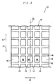
- a plurality of rectangular blocks 18 are provided on a tread 12 of a pneumatic tire 10 by dividing the tread 12 by plural circumferential-direction grooves 14 that extend along a tire circumferential direction (the direction of arrow A and the direction of arrow B) and by plural lug grooves 16 that intersect the circumferential-direction grooves 14 and extend along a tire widthwise direction (the directions of arrow W).
- a tread surface 20 of the blocks 18 includes a flat portion 22 (hatched portion in the drawing) that coincides with a tire (tread) outer contour configuration.
- reference numeral 18A denotes a leading edge of the block 18
- reference numeral 18B denotes a trailing edge of the block 18.
- the height of the trailing edge 18B (measured from a groove bottom) is constant, but the height of the leading edge 18A differs in the tire widthwise direction.
- a chamfered portion 24 is formed at a corner portion at a tire widthwise-direction outer side (direction of arrow D side) of the leading edge 18A of the block 18 (it should be noted that the block 18 shown in Figure 1 is a block 18 positioned to the right side of a tire equatorial plane CL of Figure 2).
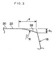
- the chamfered portion 24 has a surface that curves (in the present embodiment, an arc having a curvature radius R) convexly towards the tire outer side and smoothly connects with the flat portion 22.
- a border 26 between the chamfered portion 24 and the flat portion 22 lies on a straight line that connects a point 28 located at the leading edge 18A and distanced by a dimension e from a tire widthwise-direction outer-side end 18Aa of the leading edge 18A towards the tire equatorial plane (direction of arrow C), with a tire widthwise-direction outer side end 18Ba of the trailing edge 18B.
- the height of the chamfered portion 24 gradually decreases from the border 26 towards the tire widthwise-direction outer side end 18Aa of the leading edge 18A. Namely, the tire widthwise-direction outer side end 18Aa of the leading edge 18A becomes the lowest portion of the leading edge 18A.
- Reference letter a in Figure 1 denotes the dimension of the block 18 in the tire widthwise direction (tire widthwise-direction lengths of the leading edge 18A and the trailing edge 18B, i.e., edges arranged in the circumferential direction), reference letter b denotes the dimension of the block 18 in the tire circumferential direction (tire circumferential-direction lengths of edges 40 and 48 arranged in the widthwise-direction), reference letter h 0 denotes the height of the block 18 (height of the flat portion 22), reference letter e denotes the tire widthwise-direction dimension of the chamfered portion 24 at the leading edge 18A, reference letter h, denotes the depth from the flat portion 22 (plane) to the lowest portion of the chamfered portion 24 (in the present embodiment, the tire widthwise-direction outer side end 18Aa), and reference letter c denotes the tire widthwise-direction dimension of the flat portion (highland portion) at the leading edge 18A.
- the flat portion 22 contacts the ground, and then the chamfered portion 24 contacts the ground. Because the height of the chamfered portion 24 gradually decreases towards the tire widthwise-direction outer side end, the leading edge 18A at the chamfered portion 24 gradually makes contact with the road surface.
- the tire widthwise-direction dimension of the flat portion 22 changes in the tire circumferential direction, i.e., because the tire widthwise-direction position of the flat portion 22 changes in the tire circumferential direction, it is possible for the entire block to gently receive stress generated at the time of rolling, whereby it is possible to suppress the level of noise generated by the block 18 at the time the block 18 contacts the ground at a low level.
- the tire widthwise-direction dimension c of the flat portion 22 at the leading edge 18A is 3 mm to 15 mm.
- the dimension c it is preferable to set the dimension c to be 0.15 to 0.75 times the dimension a.
- the depth h 1 it is preferable to set the depth h 1 to be 0.1 mm to 2.5 mm.
- the present embodiment is an example in which the pneumatic tire 10 of the first embodiment is reversed when put on a vehicle (i.e., the direction of arrow B in Figure 1 is the direction in which the tire rotates when the vehicle moves forward).
- the portion that was the leading edge 18A in the first embodiment becomes the trailing edge
- the portion that was the trailing edge 18B in the first embodiment becomes the leading edge
- the chamfered portion 24 of the trailing edge separates from the road surface at first, and then the flat portion 22 of the trailing edge separates from the road surface.
- the trailing edge does not separate from the road surface all at once but gradually. Therefore, it is possible to suppress the noise level when the block 18 separates from the road surface at a low level.
- a chamfered portion 30 that is the same as the chamfered portion 24 is formed at the tire equatorial plane side (direction of arrow C side) of the trailing edge 18B.
- a border 32 between the chamfered portion 30 and the flat portion 22 lies on a straight line that connects a point 34 located at the trailing edge 18B and distanced by a dimension e' from a tire equatorial plane side end 18Bb of the trailing edge 18B towards the tire widthwise-direction outer side, with a tire equatorial plane side end 18Ab of the leading edge 18A.
- the height of the chamfered portion 30 gradually decreases from the border 32 towards the tire equatorial plane side end 18Bb of the trailing edge 18B. Namely, the tire equatorial plane side end 18Bb of the trailing edge 18B becomes the lowest portion of the trailing edge 18B.
- the chamfered portion structure of the first embodiment is combined with the chamfered portion structure of the second embodiment, and it is possible to suppress both the level of noise generated when the blocks 18 contact the road surface and the level of noise generated when the blocks 18 separate from the road surface at low levels, whereby the noise level of the tire can be suppressed even more lowly.
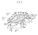
- a chamfered portion 36 is formed at the tire widthwise-direction outer side of the leading edge 18A
- a chamfered portion 38 is formed at the tire widthwise-direction outer side of the trailing edge 18B
- a chamfered portion 42 is formed at the tire equatorial plane side edge 40, whereby the entire flat portion 22 curves in a substantially circular arc.
- the tire widthwise-direction outer side end 18Aa of the leading edge 18A is the lowest portion of the chamfered portion 36, and that the height of the chamfered portion 36 gradually decreases from a border 37 between the flat portion 22 and the chamfered portion 36 towards the tire widthwise direction outer side end 18Aa.
- the tire widthwise-direction outer side end 18Ba of the trailing edge 18B is the lowest portion of the chamfered portion 38, and the height of the chamfered portion 38 gradually decreases from a border 39 between the flat portion 22 and the chamfered portion 38 towards the tire widthwise-direction outer side end 18Bb.
- the longitudinal-direction center portion of the tire equatorial plane side edge 40 is the lowest portion of the chamfered portion 42, and the height of the chamfered portion 42 gradually decreases from a border 43 between the flat portion 22 and the chamfered portion 42 towards the longitudinal-direction center of the edge 40.
- a chamfered portion 44 is formed at the tire widthwise-direction outer side of the leading edge 18A
- a chamfered portion 46 is formed at the tire equatorial plane outer side of the trailing edge 18B
- a chamfered portion 50 is formed at the trailing edge 18B side of the tire widthwise-direction outer side edge 48
- a chamfered portion 52 is formed at a leading edge 18A side of the tire equatorial plane side edge 40, whereby the entire flat portion 22 curves in a substantial S-shape.
- the tire widthwise-direction outer side end 18Aa of the leading edge 18A is the lowest portion of the chamfered portion 44, and that the height of the chamfered portion 44 gradually decreases from a border 45 between the flat portion 22 and the chamfered portion 44 towards the tire widthwise-direction outer side end 18Aa.
- the tire equatorial plane side end 18Bb of the trailing edge 18B is the lowest portion of the chamfered portion 46, and the height of the chamfered portion 46 gradually decreases from a border 47 between the flat portion 22 and the chamfered portion 46 towards the tire widthwise-direction outer side end 18Bb.
- the circumferential-direction center portion of the chamfered portion 50 is the lowest portion of the chamfered portion 50 at the tire widthwise-direction outer side edge 48, and the height of the chamfered portion 50 gradually decreases from a border 51 between the flat portion 22 and the chamfered portion 50 towards the circumferential-direction center of the chamfered portion 50 of the edge 48.
- the circumferential-direction center portion of the chamfered portion 52 is the lowest portion of the chamfered portion 52 provided at the tire equatorial plane side edge 40, and the height of the chamfered portion 52 gradually decreases from a border 53 between the flat portion 22 and the chamfered portion 52 towards the circumferential-direction center of the chamfered portion 52 of the edge 40.
- a rib 58 is provided on the tire equatorial plane CL, and parallelogrammatic blocks 60 are provided at both sides of the rib 58, by dividing the tread 12 of the pneumatic tire 10 by plural circumferential-direction grooves 54 that extend along the tire circumferential direction (the direction of arrow A and the direction of arrow B) and by plural slanted grooves 56 that extend in the tire widthwise direction from the circumferential-direction grooves 54 and slant with respect to the tire widthwise direction.
- a tread surface 62 of the block 60 includes a flat portion (hatched portion in the drawings) 64 that coincides with a tire outer contour configuration.
- reference numeral 60A denotes a leading edge of the block 60
- reference numeral 60B denotes a trailing edge of the block 60.
- each of the height of the trailing edge 60B and the height of the leading edge 60A differs in the tire widthwise direction.
- a chamfered portion 66 is formed at a corner portion at the tire widthwise-direction outer side (direction of arrow D side) of the leading edge 60A, and a chamfered portion 68 is formed at a comer portion at the tire equatorial plane side of the trailing edge 60B.
- the chamfered portion 66 and the chamfered portion 68 are curved surfaces that smoothly connect with the flat portion 64.
- a border 70 between the chamfered portion 66 and the flat portion 64 lies on a straight line that connects a point 72 located at the leading edge 60A and distanced by a dimension c from a tire equatorial plane side end 60Ab of the leading edge 60A towards the tire widthwise direction outer side, with a tire widthwise-direction outer side end 60Ba of the trailing edge 18B.
- the height of the chamfered portion 66 gradually decreases from the border 70 towards a tire widthwise-direction outer side end 60Aa of the leading edge 60A. Namely, the tire widthwise-direction outer side end 60Aa of the leading edge 60A becomes the lowest portion of the leading edge 60A.
- a border 74 between the chamfered portion 68 and the flat portion 64 lies on a straight line that connects a point 76 located at the trailing edge 60B and distanced by a dimension c' from a tire widthwise direction outer side end 60Ba of the trailing edge 60B towards the tire equatorial plane side, with a tire equatorial plane side end 60Ab of the leading edge 60A.
- the height of the chamfered portion 68 gradually decreases from the border 74 towards a tire equatorial plane side end 60Bb of the trailing edge 60B. Namely, the tire equatorial plane side end 60Bb of the trailing edge 60B becomes the lowest portion of the trailing edge 60B.
- reference letter a denotes the dimension of the block 60 in the tire widthwise direction (i.e., tire widthwise-direction dimension of the leading edge 60A and the trailing edge 60B)
- reference letter b denotes the circumferential direction dimension of edges 78 and 80 of the block 60 arranged in the tire widthwise direction
- reference letter h 0 denotes the height of the block 60
- reference letter e denotes the tire widthwise-direction length of the chamfered portion 66 at the leading edge 60A
- reference letter h 1 denotes the depth from the flat portion 64 (plane) to the lowest portion of the chamfered portion 66 (in the present embodiment, the tire widthwise-direction outer side end 60Aa)
- reference letter c denotes the tire widthwise-direction dimension of the flat portion (highland portion) at the leading edge 60A
- reference letter e' denotes the tire widthwise-direction length of the chamfered portion 68 at the trailing edge 60B
- the leading edge 60A of the block 60 gradually makes contact with the ground, and the trailing edge 60B of the block 60 gradually separates from the road surface. Furthermore, because the position of the flat portion 64 changes in the tire widthwise direction, it is possible to suppress the level of noise generated by the block 18 at a low level.
- Tire of Conventional Example 1 a tire including a tread provided with rectangular blocks in which the tread surface was flat (along the tire outer contour configuration) and having no chamfered portions formed thereon.
- the tread pattern was the same as the pattern of Figure 2.
- the dimension b was 30 mm
- the dimension a was 20 mm
- the height h 0 was 10 mm
- the dimension b was 30 mm
- the dimension a was 50 mm
- the height h 0 was 10 mm.
- Tire of Conventional Example 2 a tire including a tread provided with, as shown in Figure 10, blocks 102 in which the tire circumferential-direction center portion thereof was flat (hatched portion) and the tire circumferential-direction sides (leading edge and trailing edge) thereof were chamfered as chamfered portions 100. With respect to the chamfered portions 100, the length in the circumferential direction was 10 mm and the depth h, was 0.5 mm. The tread pattern and the outer shape dimension of the blocks 100 were the same as in Conventional Example 1.
- Tire of Conventional Example 3 a tire including a tread provided with, as shown in Figure 11, blocks 106 in which the tire circumferential-direction center portion thereof was flat (hatched portion) and the tire widthwise-direction sides thereof were chamfered as chamfered portions 104. With respect to the chamfered portions 104, the length i in the tire widthwise direction was 6 mm and the depth h 1 was 0.5 mm. The tread pattern and the outer shape dimension of the blocks 106 were the same as in Conventional Example 1.
- test tires were all 195/65R14.
- Pneumatic tire of Example 1 the pneumatic tire of the preceding first embodiment, with the outer shape dimension of the blocks being the same as that of Conventional Example 1.
- the tire widthwise-direction length e of the chamfered portion in the leading edge was 17 mm in the three rows of blocks in the center and 17 mm in the shoulder blocks.
- the depth h 1 of the chamfered portion was 0.5 mm.
- Example 1 The sizes of the test tires were both 195/65R14. Noise Level Index Conventional Example 1 100 Example 1 94
- the pneumatic tire of the conventional example 1 and a pneumatic tire of Example 2, to which the invention was applied were prepared.
- a test was conducted in the same manner as in Test Example 1, and noise was evaluated.
- Pneumatic tire of Example 2 the pneumatic tire of the preceding second embodiment.
- the outer shape dimension of the blocks was the same as that of Conventional Example 1.
- the tire widthwise-direction length e of the chamfered portion in the trailing edge was 17 mm in the three rows of blocks in the center and 17 mm in the shoulder blocks.
- the depth h 1 of the chamfered portion was 0.5 mm.
- Example 2 93
- the pneumatic tire of the conventional example 1 and a pneumatic tire of Example 3, to which the invention was applied were prepared.
- a test was conducted in the same manner as in Test Example 1, and noise was evaluated.
- Example 3 the pneumatic tire of the preceding third embodiment.
- the outer shape dimension of the blocks was the same as that of Conventional Example 1, and the dimensions of the chamfered portions were the same as those in Examples 1 and 2.
- Example 3 91
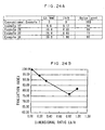
- Pneumatic tires of Examples 4 to 8 as shown in Figure 12, a chamfered portion was provided at each of the leading edge and the trailing edge, and the circumferential-direction length f of the flat portion at the tire equatorial plane side edge and at the tire widthwise-direction outer side edge was varied as shown in Table 5 below.
- the pattern and outer shape dimension of the blocks were the same as those in Conventional Example 1. Also, the tire widthwise-direction length e of the chamfered portion 24 at the leading edge 18A was 17 mm in the three rows of blocks in the center and 17 mm in the shoulder blocks. The depth h 1 of the chamfered portion 24 was 0.5 mm.
- the tire widthwise-direction length e' of the chamfered portion 30 at the trailing edge 18B was 17 mm in the three rows of blocks in the center and 17 mm in the shoulder blocks.
- the depth h 2 of the chamfered portion 30 was 0.5 mm.
- the pneumatic tire of the conventional example 1 and pneumatic tires of Examples 9 and 10, to which the invention was applied were prepared. A test was conducted in the same manner as in Test Example 1, and noise was evaluated.
- the pneumatic tire of Example 9 was the pneumatic tire of the preceding fourth embodiment (see Figure 5)
- the pneumatic tire of Example 10 was the pneumatic tire of the preceding fifth embodiment (see Figure 6).
- the depth h 1 of the chamfered portion 36 was 0.5 mm
- the circumferential-direction length j of the chamfered portion 36 at the tire widthwise-direction outer side edge 48 was 15 mm
- the depth h 2 of the chamfered portion 38 was 0.5 mm
- the circumferential-direction length k of the chamfered portion 38 at the tire widthwise-direction outer side edge 48 was 15 mm
- the depth h 3 of the chamfered portion 42 was 0.5 mm.
- the dimension in the tire widthwise direction of the flat portion 22 was 3 mm (constant) in the three rows of blocks in the center and 3 mm (constant) in the shoulder blocks.
- the depth h 1 of the chamfered portion 44 was 0.5 mm
- the circumferential-direction length m of the chamfered portion 44 at the tire widthwise-direction outer side edge 48 was 10 mm
- the depth h 2 of the chamfered portion 46 was 0.5 mm
- the circumferential-direction length n of the chamfered portion 46 at the tire equatorial plane side edge 40 was 10 mm
- the circumferential-direction length o of the chamfered portion 50 at the tire widthwise-direction outer side edge 48 was 20 mm
- the circumferential-direction length q of the chamfered portion 52 at the tire equatorial plane side edge 40 was 20 mm
- the depth h 3 of the chamfered portion 50 was 0.5 mm
- the depth h 4 of the chamfered portion 52 was 0.5 mm.
- the dimension in the tire widthwise direction of the flat portion 22 was 3 mm (constant) in the three rows
- Example 10 The sizes of the test tires were all 195/65R14. Noise Level Index Conventional Example 1 100 Example 9 91 Example 10 93
- the pneumatic tire of Conventional Example 1 and pneumatic tires of Examples 11 to 15, to which the invention was applied were prepared.
- a test was conducted in the same manner as in Test Example 1, and noise was evaluated.
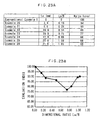
- the pneumatic tires of Examples 11 to 15 were, as shown in Figure 1, pneumatic tires provided with the chamfered portion 24 at the tire widthwise-direction outer side end side of the leading edge 18A of the block 18, but the tire widthwise-direction dimension c of the flat portion 22 at the leading edge 18A was, as shown in Table 7 below, different.
- Example 11 0 97
- Example 12 3 91
- Example 13 10
- Example 14 15
- Example 15 16 97
- Table 8 shows the relation between a ratio c/a and noise level, wherein "a” being the dimension a in the tire widthwise direction of the leading edge 18A of the block and "c” being the tire widthwise-direction dimension c of the flat portion at the leading edge.
- Example 11 0 97
- Example 12 0.15
- Example 13 0.5
- Example 14 0.75
- Example 15 0.8 97
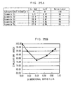
- Table 9 shows the relation between the tire widthwise-direction length e of the chamfered portion 24 at the leading edge 18A and noise level.
- Example 11 20 97
- Example 12 17 91
- Example 13 10 92
- Example 14 5 94
- Example 15 4 97
- Table 10 shows the relation between a ratio e/a and noise level, wherein "a” being the dimension a in the tire widthwise direction of the leading edge 18A of the block and "e” being the tire widthwise-direction dimension e of the chamfered portion 24 at the leading edge 18A.
- Example 11 1 97
- Example 12 0.85
- Example 13 0.5
- Example 14 0.25
- Example 15 0.2 97
- the pneumatic tire of Conventional Example 1 pneumatic tires of Examples 16 to 20, to which the invention was applied, and a pneumatic tire of Comparative Example 1 were prepared.
- a test was conducted in the same manner as in Test Example 1, and noise was evaluated.
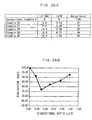
- the pneumatic tires of Examples 16 to 20 and the pneumatic tire of Comparative Example 1 were, as shown in Figure 1, pneumatic tires provided with the chamfered portion 24 at the tire widthwise-direction outer side end side of the leading edge 18A of the block 18, but the depth h, of the chamfered portion of each tire was, as shown in Table 7 below, different.
- Example 16 0.1 95
- Example 17 0.5 91
- Example 18 1.2 94
- Example 19 2.5 95 Comparative Example 1 2.8 103
- Example 16 0.01 95
- Example 17 0.05
- Example 18 0.12
- Example 19 0.25
- Embodiment 20 it was a pneumatic tire having a directional pattern provided with parallelogrammatic blocks as shown in Figure 7, and chamfered portions 66 and 68 were provided as shown in Figures 8 and 9.
- the width of the rib 58 was 10 mm
- the groove width of the circumferential-direction grooves 54 was 8 mm
- the groove width of the slanted grooves 56 was 7 mm.
- the tire widthwise-direction dimension a was 25 mm
- the tire circumferential-direction dimension b of the edges arranged in the tire widthwise-direction was 30 mm
- the height h 0 was 10 mm
- the depths h 1 and h 2 were 0.5 mm
- the angle ⁇ was 40 degrees
- the tire widthwise-direction dimension c of the flat portion 64 was 3 mm.
- the dimensions of the blocks 60 at the shoulders were the same as those of the blocks 60 at the rib 58 sides.
- Example 4 included the same pattern as the pneumatic tire of Example 20, but included blocks on which chamfered portions were not formed.
- Example 20 90
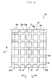
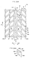
- plural rectangular center blocks 18a, second blocks 18b, and shoulder blocks 18c are provided on the tread 12 of the pneumatic tire 10, respectively, by dividing the tread 12 by plural circumferential-direction grooves 14 that extend along the tire circumferential direction (the direction of arrow A and the direction opposite from the direction of arrow A) and by plural lug grooves 16 that extend along the tire widthwise direction (the direction of arrow R and the direction of arrow L) and intersect the circumferential-direction grooves 14.
- a tread surface of the shoulder blocks 18c includes the flat portion 22 that coincides with a tire (tread) outer contour configuration.
- reference numeral 18E denotes a ground-contact end
- reference numeral 18A denotes a leading edge of the shoulder block 18c
- reference numeral 18B denotes a trailing edge of the shoulder block 18c.
- a first chamfered portion 24 is formed at a comer portion at the tire equatorial plane side of the leading edge 18A of the shoulder block 18c (it should be noted that the shoulder block 18c shown in Figure 13 is a shoulder block 18c positioned to the right side of the tire equatorial plane CL of Figure 14).
- the first chamfered portion 24 is a convex curved surface (in the present embodiment, a circular arc curved surface) that smoothly connects with the flat portion 22.
- a border 26 between the first chamfered portion 24 and the flat portion 22 is diagonal with respect to the tire circumferential direction, and the height of the first chamfered portion 24 gradually decreases from the border 26 towards a tire equatorial plane side end 18Aa of the leading edge 18A.
- the tire equatorial plane side end 18Aa of the leading edge 18A becomes the lowest portion of the leading edge 18A within a ground-contact surface.
- a second chamfered portion 28 is formed at an intermediate portion of the trailing edge 18B of the shoulder block 18c.
- the second chamfered portion 28 has a convex curved surface (in the present embodiment, a circular arc curved surface) that smoothly connects with the flat portion 22.
- a border 30 between the second chamfered portion 28 and the flat portion 22 has a substantially circular arc configuration, and the height of the second chamfered portion 28 gradually decreases from the border 30 towards a circular arc center of border 30.
- Reference letter A denotes the dimension measured along the tire circumferential direction of the end edge 18D on the tire equatorial plane side
- reference letter B denotes the dimension measured, in the tire widthwise-outer-side direction, from the end edge 18D on the tire equatorial plane side of the shoulder block 18c to the ground-contact end 18E
- reference letter C denotes block height at the end edge 18D on the tire equatorial plane side of the shoulder block 18c
- reference letter Ha denotes the depth at the lowest portion of the first chamfered portion 24 (in the present embodiment, the tire equatorial plane side end 18Aa) from the flat portion 22 (plane)
- reference letter La denotes the dimension of the first chamfered portion 24 measured from the end edge 18D on the tire equatorial plane side 24 towards the tire widthwise-direction outer side
- reference letter Lb denotes the dimension of the first chamfered portion 24 measured along the tire circumferential direction from the leading edge 18A
- Dimension Ha is preferably 0.2 mm to 2.5 mm.
- Ratio Ha/C is preferably 0.02 to 0.25.
- Dimension Hb is preferably 0.2 mm to 2.5 mm.
- Ratio Hb/C is preferably 0.02 to 0.25.
- Dimension La is preferably 5 mm or greater.
- Ratio La/B is preferably 0.25 or greater.
- Dimension Lb is preferably 10 mm or greater.
- Ratio Lb/A is preferably 0.3 or greater.
- Dimension Lc is preferably 2 mm to 25 mm.
- Ratio Lc/A is preferably 0.17 to 0.83.
- Dimension Ld is preferably 3 mm to 15 mm.
- Ratio Ld/B is preferably 0.15 to 0.75.
- Ratio Le is preferably 2 mm to 15 mm.
- Ratio Le/B is preferably 0.1 to 0.75.
- Dimension Lf is preferably 2 mm or greater.
- Ratio Lf/B is preferably 0.1 or greater.
- the first chamfered portion 24 gradually makes contact with the road surface.
- the tire widthwise-direction dimension of the flat portion 22 changes in the tire circumferential direction, i.e., because the tire widthwise-direction position of the flat portion 22 changes in the tire circumferential direction, it is possible for the entire block to gently receive stress generated at the time of rolling, whereby it is possible to suppress the level of noise generated by the shoulder block 18c at the time the shoulder block 18c contacts the ground at a low level.
- the trailing edge 18B of the shoulder block 18c does not separate from the road surface all at once but gradually. Therefore, it is possible to suppress the generation of noise when the shoulder block 18c separates from the road surface.
- the dimension Ha, the ratio Ha/C, the dimension Hb, the ratio Hb/C, the dimension La, the ratio La/B, the dimension Lb, the ratio Lb/A, the dimension Lc, the ratio Lc/A, the dimension Ld, the ratio Ld/B, the dimension Le, the ratio Le/B, the dimension Lf, and the ratio Lf/B fall outside of the aforementioned ranges, it becomes impossible to sufficiently suppress the generation of noise.
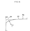
- the second chamfered portion 28 is disposed closer to the tire equatorial plane side than to the ground-contact end 18E in Figure 13, the second chamfered portion 28 may also be disposed such that a portion thereof extends to the tire widthwise-direction outer side beyond the ground-contact end 18E, as shown in Figure 17.
- the flat portion 22 and at least one of the first chamfered portion 24 and the second chamfered portion 28 are provided in any portion in the tire circumferential direction when the shoulder block 18c is seen in cross section along the tire widthwise direction.
- chamfered portions 32 which are the same as the first chamfered portion 24, at opposite comers at the leading side and at the trailing side in the center blocks 18a and in the second blocks 18b.
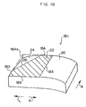
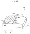
- first chamfered portion 24 and the second chamfered portion 28 were disposed on the shoulder block 18c in the preceding embodiment, the present invention is not limited to the same. While the effects may drop somewhat, it is also possible to provide only the first chamfered portion 24 on the shoulder block 18c, as shown in Figure 19, or to provide only the second chamfered portion 28 on the shoulder block 18c, as shown in Figure 20.
- the lug grooves 16 may also slant (angle ⁇ ) with respect to the tire widthwise direction, as shown in Figure 31.
- the chamfered portion 32 is provided at opposite comers at the leading side and at the trailing side in the center blocks 18a and in the second blocks 18b, as in Figure 18.
- ground-contacting pressure of the pattern of Figure 31 is shown. The higher the dot density of portions at the ground-contacting surface is, the higher is the ground-contacting pressure, and the lower the dot density of portions at the ground-contacting surface is, the lower is the ground-contacting pressure.
- test measured sound pressure peaks of sound pressure waveforms
- Test Example 1 a test was conducted with respect to a tire provided with the tread pattern (monopitch) shown in Figure 14.
- the size of the test tires was 195/65R15.
- dimension A was 30 mm
- dimension B was 20 mm
- dimension C was 10 mm (see Figure 13).
- the width of the ground contact region in the shoulder blocks was equivalent to dimension B (20 mm).
- Tire of Conventional Example 1 a tire having no chamfered portions formed thereon and in which the tread surface of the shoulder blocks was flat (along the tire outer contour configuration) (see Figure 30).
- Tire of Example 1 a tire in which a chamfered portion was formed at a corner on the leading side of the shoulder block, as shown in Figure 19.
- Dimensions and ratios were as listed below in Table 14.
- Dimension A 30 mm B 20 mm C 10 mm Ha 0.5 mm Hb 0 La 15 mm Lb 25 mm Lc 0 Ld 0 Le 0 Lf 0
- Test Example 2 a test was conducted in a manner similar to Test Example 1 with respect to a tire provided with the tread pattern (monopitch) shown in Figure 14, but only the configuration of the shoulder blocks was different.
- Tire of Example 2 a tire having a chamfered portion formed at the trailing edge of the shoulder block, as shown in Figure 20. Dimensions and ratios were as listed below in Table 16. Dimension A 30 mm B 20 mm C 10 mm Ha 0 Hb 0.5 mm La 0 Lb 0 Lc 12 mm Ld 6 mm Le 7 mm Lf 7 mm Ratio Ha/C 0 Hb/C 0.05 La/B 0 Lb/A 0 Lc/A 0.4 Ld/B 0.3 Le/B 0.35 Lf/B 0.35
- Test Example 3 a test was conducted in a manner similar to Test Examples 10 and 11 with respect to a tire provided with the tread pattern (monopitch) shown in Figure 14, but only the configuration of the shoulder blocks was different.
- Tire of Example 3 a tire having a chamfered portion formed at the leading side corner of the shoulder block and at the trailing edge of the shoulder block, respectively, as shown in Figure 13. Dimensions and ratios were as listed below in Table 18. Dimension A 30 mm B 20 mm C 10 mm Ha 0.5 mm Hb 0.5 mm La 15 mm Lb 25 mm Lc 12 mm Ld 6 mm Le 7 mm Lf 7 mm Ratio Ha/C 0.05 Hb/C 0.05 La/B 0.75 Lb/A 0.83 Lc/A 0.4 Ld/B 0.3 Le/B 0.35 Lf/B 0.35
- Test Example 4 a test was conducted in a manner similar to Test Example 10 with respect to a tire provided with the tread pattern (monopitch) shown in Figure 14.
- Tires of Examples 4 to 11 tires having a chamfered portion formed at the leading side comer of the shoulder block, as shown in Figure 19, with La being fixed at 15 mm, Lb being fixed at 25 mm, and the dimension Ha being varied.
- Ha in order to sufficiently reduce noise level, it is best for Ha to be 0.2 to 2.5 mm and for Ha/C to be 0.02 to 0.25.
- Test Example 14 a test was conducted in a manner similar to Test Example 10 with respect to a tire provided with the tread pattern (monopitch) shown in Figure 14.
- Tires of Examples 12 to 19 tires having a chamfered portion formed at the trailing side of the shoulder block, as shown in Figure 20, with Lc being fixed at 12 mm, Ld being fixed at 6 mm, Le being fixed at 7 mm, Lf being fixed at 7 mm, and the dimension Hb being varied.
- Hb in order to sufficiently reduce noise level, it is best for Hb to be 0.2 to 2.5 mm and for Hb/C to be 0.02 to 0.25.
- Test Example 15 a test was conducted in a manner similar to Test Example 10 with respect to a tire provided with the tread pattern (monopitch) shown in Figure 14.
- Tires of Examples 20 to 26 tires having a chamfered portion formed at the leading side comer of the shoulder block, as shown in Figure 19, with Lb being fixed at 25 mm, Ha being fixed at 0.5 mm, and the dimension La being varied.
- La in order to sufficiently reduce noise level, it is best for La to be 0.2 to 2.5 mm and for La/B to be 0.02 to 0.25.
- Test Example 16 a test was conducted in a manner similar to Test Example 10 with respect to a tire provided with the tread pattern (monopitch) shown in Figure 14.
- Tires of Examples 27 to 30 tires having a chamfered portion formed at the leading side comer of the shoulder block, as shown in Figure 19, with La being fixed at 15 mm, Ha being fixed at 0.5 mm, and the dimension Lb being varied.
- Lb 10 mm or greater and for Lb/A to be 0.3 or greater.
- Test Example 17 a test was conducted in a manner similar to Test Example 10 with respect to a tire provided with the tread pattern (monopitch) shown in Figure 14.
- Tires of Examples 31 to 35 tires having a chamfered portion formed at the leading side comer of the shoulder block, as shown in Figure 19, with Ld being fixed at 6 mm, Le being fixed at 7 mm, Lf being fixed at 7 mm, Hb being fixed at 0.5 mm, and the dimension Lc being varied.
- Lc in order to sufficiently reduce noise level, it is best for Lc to be 5 mm to 25 mm and for Lc/A to be 0.17 to 0.83.
- Test Example 18 a test was conducted in a manner similar to Test Example 10 with respect to a tire provided with the tread pattern (monopitch) shown in Figure 14.
- Tires of Examples 36 to 40 tires having a chamfered portion formed at the trailing side of the shoulder block, as shown in Figure 20, with Lc being fixed at 12 mm, Le being fixed at 7 mm, Lf being fixed at 7 mm, Hb being fixed at 0.5 mm, and the dimension Ld being varied.
- Ld in order to sufficiently reduce noise level, it is best for Ld to be 3 mm to 15 mm and for Ld/B to be 0.15 to 0.75.
- Test Example 19 a test was conducted in a manner similar to Test Example 10 with respect to a tire provided with the tread pattern (monopitch) shown in Figure 14.
- Tires of Examples 41 to 45 tires having a chamfered portion formed at the trailing side of the shoulder block, as shown in Figure 20, with Ld being fixed at 6 mm, Lc being fixed at 12 mm, Lf being fixed at 7 mm, Hb being fixed at 0.5 mm, and the dimension Le being varied.
- Le in order to sufficiently reduce noise level, it is best for Le to be 2 mm to 15 mm and for Le/B to be 0.10 to 0.75.
- Test Example 20 a test was conducted in a manner similar to Test Example 10 with respect to a tire provided with the tread pattern (monopitch) shown in Figure 14.
- Tires of Examples 46 to 50 tires having a chamfered portion formed at the trailing side of the shoulder block, as shown in Figure 20, with Ld being fixed at 6 mm, Lc being fixed at 12 mm, Le being fixed at 7 mm, Hb being fixed at 0.5 mm, and the dimension Lf being varied.
- Lf in order to sufficiently reduce noise level, it is best for Lf to be 2 mm or greater and for Lf/B to be 0.10 or greater.
- Test Example 21 a test was conducted in a manner similar to Test Examples 10 and 11 with respect to a tire provided with the tread pattern shown in Figure 29A.
- the size of the tires was 195/65R14.
- dimension A was 30 mm
- dimension B was 25 mm
- the height was 10 mm
- the width of the ground-contacting region thereof corresponded to the dimension B (25 mm).
- Lug grooves 16 were slanted at 40° with respect to the tire widthwise direction.
- a width D of a rib 19 on the tire equatorial plane CL was 13 mm.
- Tires of Conventional Example 2 a tire in which the tread surface of the shoulder blocks 18c was flat (along the tire outer contour configuration) and having no chamfered portion formed on the shoulder blocks 18c.
- Tire of Example 51 a tire having a first chamfered portion 24 formed at the trailing side comer of the end edge 18D on the tire equatorial plane side of the shoulder block 18c and a second chamfered portion 28 formed at the leading edge, as shown in Figure 29B.
- the pneumatic tire relating to the present invention is suitable for use in automobiles and suitable for reducing tire noise without compromising other characteristics.
Landscapes
- Engineering & Computer Science (AREA)
- Mechanical Engineering (AREA)
- Tires In General (AREA)
Abstract
Description
| Noise Level Index | |
| Conventional Example 1 | 100 |
| Conventional Example 2 | 115 |
| Conventional Example 3 | 103 |
| Noise Level Index | |
| Conventional Example 1 | 100 |
| Example 1 | 94 |
| Noise Level Index | |
| Conventional Example 1 | 100 |
| Example 2 | 93 |
| Noise Level Index | |
| Conventional Example 1 | 100 |
| Example 3 | 91 |
| f (mm) | Noise Level Index | |
| Example 4 | 0 | 91 |
| Example 5 | 10 | 93 |
| Example 6 | 15 | 94 |
| Example 7 | 20 | 96 |
| Example 8 | 25 | 98 |
| Conventional Example 1 | 30 | 100 |
| Noise Level Index | |
| Conventional Example 1 | 100 |
| Example 9 | 91 |
| Example 10 | 93 |
| c (mm) | Noise Level Index | |
| Conventional Example 1 | 100 | |
| Example 11 | 0 | 97 |
| Example 12 | 3 | 91 |
| Example 13 | 10 | 92 |
| Example 14 | 15 | 94 |
| Example 15 | 16 | 97 |
| c/a | Noise Level Index | |
| Conventional Example 1 | 100 | |
| Example 11 | 0 | 97 |
| Example 12 | 0.15 | 91 |
| Example 13 | 0.5 | 92 |
| Example 14 | 0.75 | 94 |
| Example 15 | 0.8 | 97 |
| e (mm) | Noise Level Index | |
| Conventional Example 1 | 100 | |
| Example 11 | 20 | 97 |
| Example 12 | 17 | 91 |
| Example 13 | 10 | 92 |
| Example 14 | 5 | 94 |
| Example 15 | 4 | 97 |
| e/a | Noise Level Index | |
| Conventional Example 1 | 100 | |
| Example 11 | 1 | 97 |
| Example 12 | 0.85 | 91 |
| Example 13 | 0.5 | 92 |
| Example 14 | 0.25 | 94 |
| Example 15 | 0.2 | 97 |
| h1 (mm) | Noise Level Index | |
| Conventional Example 1 | 100 | |
| Example 16 | 0.1 | 95 |
| Example 17 | 0.5 | 91 |
| Example 18 | 1.2 | 94 |
| Example 19 | 2.5 | 95 |
| Comparative Example 1 | 2.8 | 103 |
| h1/h0 | Noise Level Index | |
| Conventional Example 1 | 100 | |
| Example 16 | 0.01 | 95 |
| Example 17 | 0.05 | 91 |
| Example 18 | 0.12 | 94 |
| Example 19 | 0.25 | 95 |
| Comparative Example 1 | 0.28 | 103 |
| Noise Level Index | |
| Conventional Example 4 | 100 |
| Example 20 | 90 |
| Dimension | A | 30 |
| B | ||
| 20 | ||
| C | ||
| 10 mm | ||
| Ha | 0.5 | |
| Hb | ||
| 0 | ||
| | 15 | |
| Lb | ||
| 25 | ||
| Lc | ||
| 0 | ||
| | 0 | |
| | 0 | |
| | 0 | |
| Ratio | Ha/C | 0.05 |
| Hb/ | 0 | |
| La/B | 0.75 | |
| Lb/A | 0.83 | |
| Lc/ | 0 | |
| Ld/ | 0 | |
| Le/ | 0 | |
| Lf/ | 0 |
| Noise Level | |
| Conventional Example 1 | 100 |
| Example 1 | 87 |
| Dimension | A | 30 |
| B | ||
| 20 | ||
| C | ||
| 10 | ||
| Ha | ||
| 0 | ||
| Hb | 0.5 | |
| La | ||
| 0 | ||
| | 0 | |
| | 12 | |
| Ld | ||
| 6 | ||
| Le | ||
| 7 | ||
| Lf | ||
| 7 mm | ||
| Ratio | Ha/ | 0 |
| Hb/C | 0.05 | |
| La/ | 0 | |
| Lb/ | 0 | |
| Lc/A | 0.4 | |
| Ld/B | 0.3 | |
| Le/B | 0.35 | |
| Lf/B | 0.35 |
| Noise Level | |
| Conventional Example 1 | 100 |
| Example 2 | 87 |
| Dimension | A | 30 |
| B | ||
| 20 | ||
| C | ||
| 10 mm | ||
| Ha | 0.5 mm | |
| Hb | 0.5 | |
| La | ||
| 15 | ||
| Lb | ||
| 25 | ||
| Lc | ||
| 12 | ||
| Ld | ||
| 6 | ||
| Le | ||
| 7 | ||
| Lf | ||
| 7 mm | ||
| Ratio | Ha/C | 0.05 |
| Hb/C | 0.05 | |
| La/B | 0.75 | |
| Lb/A | 0.83 | |
| Lc/A | 0.4 | |
| Ld/B | 0.3 | |
| Le/B | 0.35 | |
| Lf/B | 0.35 |
| Noise Level | |
| Conventional Example 1 | 100 |
| Example 3 | 77 |
| Dimension | A | 30 |
| B | ||
| 25 | ||
| C | ||
| 10 mm | ||
| Ha | 0.5 mm | |
| Hb | 0.5 mm | |
| La | 18.75 | |
| Lb | ||
| 25 | ||
| Lc | ||
| 12 mm | ||
| Ld | 7.5 mm | |
| Le | 8.75 mm | |
| Lf | 8.75 mm | |
| Ratio | Ha/C | 0.05 |
| Hb/C | 0.05 | |
| La/B | 0.75 | |
| Lb/A | 0.83 | |
| Lc/A | 0.4 | |
| Ld/B | 0.3 | |
| Le/B | 0.35 | |
| Lf/B | 0.35 |
| Noise Level | |
| Conventional Example 2 | 100 |
| Example 51 | 81 |
Claims (35)
- A pneumatic tire including a tread having plural blocks divided by plural grooves that mutually intersect, characterized in that:height of each block at the leading side edge thereof varies in a tire widthwise direction, a portion of the leading side edge that initially contacts a road surface being a "highland" portion which is positioned on a tire radial-direction outer side than the remaining portion of the leading side edge that later contacts the road surface; andthe highland portion extends in a tire circumferential direction and the position of the highland portion in the tire widthwise-direction is changed in the tire circumferential direction.
- A pneumatic tire including a tread having plural blocks divided by plural grooves that mutually intersect, characterized in that:height of each block at the trailing side edge thereof varies in a tire widthwise direction, a portion of the trailing side edge that lastly separates from a road surface being a "highland" portion which is positioned on a tire radial-direction outer side than the remaining portion of the trailing side edge that initially separates from the road surface; andthe highland portion extends in a tire circumferential direction and the position of the highland portion in the tire widthwise-direction is changed in the tire circumferential direction.
- A pneumatic tire including a tread having plural blocks divided by plural grooves that mutually intersect, characterized in that:wherein each of the first highland portion and the second highland portion extends in a tire circumferential direction and the position of the highland portion in the tire widthwise-direction is changed in the tire circumferential direction.each of leading side edges and trailing side edges of the blocks has a height that differs in a tire widthwise direction;a portion of the leading side edge that initially contacts a road surface being a first "highland" portion which is positioned on a tire radial-direction outer side than the remaining portion of the leading side edge that later contacts the road surface; anda portion of the trailing side edge that lastly separates from a road surface being a second "highland" portion which is positioned on a tire radial-direction outer side than the remaining portion of the trailing side edge that initially separates from the road surface,
- The pneumatic tire of claim 3, wherein the first highland portions and the second highland portions are connected such that they are continuous in the tire circumferential direction.
- The pneumatic tire of any one of claims 1 to 4, wherein portions lower than the highland portions are formed as smoothly curved surfaces whose height gradually decreases towards block edges.
- The pneumatic tire of any one of claims 1 to 5, wherein when the blocks are viewed in cross section along the tire widthwise direction, the highland portions and the portions lower than the highland portions are provided in any portions at tire circumferential-direction positions.
- The pneumatic tire of any one of claims 1 to 6, wherein in a tread surface of the blocks, the highland portions include flat portions that coincide with an outer contour configuration of the tire.
- The pneumatic tire of claim 7, wherein in the block edges in the tire circumferential direction, a tire widthwise-direction dimension of the flat portion is in a range of 3 mm to 15 mm (inclusive of 3 mm and 15 mm).
- The pneumatic tire of claim 7 or claim 8, wherein in the block edges in the tire circumferential direction, the tire widthwise-direction dimension of the flat portion is 0.15 to 0.75 times a tire widthwise-direction dimension of the block edges.
- The pneumatic tire of any one of claims 1 to 9, wherein in the block edges in the tire circumferential direction, a depth dimension in a block height direction from a highest portion of the highland portion to a lowest portion of the tread surface is within a range of 0.1 mm to 2.5 mm (inclusive of 0.1 mm and 2.5 mm).
- The pneumatic tire of any one of claims 1 to 10, wherein in the block edges in the tire circumferential direction, the depth dimension in the block height direction from the highest portion of the highland portion to the lowest portion of the tread surface is 0.01 to 0.25 times a maximum height of the highland portion.
- The pneumatic tire of any one of claims 1 to 11, wherein in the block edges in the tire circumferential direction, a tire widthwise-direction length of the portions lower than the highland portions is 5 mm to 17 mm (inclusive of 5 mm and 17 mm).
- The pneumatic tire of any one of claims 1 to 12, wherein in the block edges in the tire circumferential direction, the tire widthwise-direction length of the portions lower than the highland portions is 0.25 to 0.85 times the tire widthwise-direction dimension of the block edges.
- The pneumatic tire of any one of claims 1 to 13, wherein in the block edges in the tire circumferential-direction of blocks disposed at places other than on a tire equatorial plane of the tread, highland portions are disposed at a tire equatorial plane side.
- A pneumatic tire including a tread having plural blocks divided by plural circumferential grooves extending in the tire circumferential direction and plural grooves that intersect the circuferential grooves, characterized in that:wherein, at ground-contact ends of the blocks at the outermost sides in the tire widthwise direction, all are highland portions along the tire outer contour.at end edges, on the tire equatorial plane side, of blocks at outermost sides in a tire widthwise direction, highland portions along a tire outer contour are disposed at one of a leading side end edge and a trailing side end edge, and first lowland portions whose block height gradually becomes lower in a direction of moving away from the highland portions are disposed at the other of theleading side end edge and the trailing side end edge,
- A pneumatic tire including a tread having plural blocks divided by plural grooves that mutually intersect, characterized in that:highland portions along a tire outer contour and second lowland portions that are lower than the highland portions and whose block height gradually becomes lower in a direction of moving away from the highland portions are disposed at a leading side edge or a trailing side edge of blocks at outermost sides in a tire widthwise direction.
- A pneumatic tire including a tread having plural blocks divided by plural grooves that mutually intersect, characterized in that:at end edges, of the tire equatorial plane side, of blocks at outermost sides in a tire widthwise direction, highland portions along a tire outer contour are disposed at one of a leading side end edge and a trailing side end edge, and first lowland portions whose block height gradually becomes lower in a direction of moving away from the highland portions are disposed at the other of the leading side end edge and the trailing side end edge; andhighland portions along a tire outer contour and second lowland portions that are lower than the highland portions and whose block height gradually becomes lower in a direction of moving away from the highland portions are disposed at the leading side edge or the trailing side edge of the blocks at the outermost sides in the tire widthwise direction not provided with the first lowland portions.
- The pneumatic tire of claim 15 or 17, wherein in the end edges on the tire equatorial plane side, of the blocks at outermost sides in the tire widthwise direction, when Ha denotes a depth dimension in a block height direction from a highest portion of the highland portion to a lowest portion of the first lowland portion, Ha is 0.2 mm to 2.5 mm.
- The pneumatic tire of any one of claims 15, 17 and 18, wherein in the end edges on the tire equatorial plane side, of the blocks at outermost sides in the tire widthwise direction, when Ha denotes a depth dimension in a block height direction from a highest portion of the highland portion to a lowest portion of the first lowland portion and C denotes block height in the end edges, on the tire equatorial plane side, of the blocks at outermost sides in the tire widthwise direction, Ha/C is 0.02 to 0.25.
- The pneumatic tire of claim 16 or claim 17, wherein in the leading side edge or trailing side edge provided with the second lowland portion, when Hb denotes a depth dimension in a block height direction from a highest portion of the highland portion to a lowest portion of the second lowland portion, Hb is 0.2 mm to 2.5 mm.
- The pneumatic tire of any one of claims 16, 17 and 20, wherein in the leading side edge or trailing side edge provided with the second lowland portion, when Hb denotes a depth dimension in a block height direction from a highest portion of the highland portion to a lowest portion of the second lowland portion and C denotes block height in the end edge, on the tire equatorial plane side, of the blocks at outermost sides in the tire widthwise direction, Hb/C is 0.02 to 0.25.
- The pneumatic tire of any one of claims 15, 17, 18 and 19, wherein when La denotes a dimension of the first lowland portion measured from the end edge on the tire equatorial plane side towards the tire widthwise-direction outer side, dimension La is 5 mm or greater.
- The pneumatic tire of any one of claims 15, 17, 18, 19 and 22, wherein when La denotes a dimension of the first lowland portion measured from the end edge on the tire equatorial plane side towards the tire widthwise-direction outer side and B denotes a dimension of the block at the outermost side in the tire widthwise direction measured, in the tire widthwise direction, from the end edge on the tire equatorial plane side to the ground-contact edge on the tire widthwise-direction outer side, La/B is 0.25 or greater.
- The pneumatic tire of any one of claims 15, 17, 18, 19, 22 and 23, wherein when Lb denotes a dimension of the first lowland portion measured along the tire circumferential direction from the leading side edge or trailing side edge provided with the first lowland portion, Lb is 10 mm or greater.
- The pneumatic tire of any one of claims 15, 17, 18, 19, 22, 23 and 24, wherein when Lb denotes a dimension of the first lowland portion measured along the tire circumferential direction from the leading side edge or trailing side edge provided with the first lowland portion and A denotes a dimension of the end edge on the tire equatorial plane side measured along the tire circumferential direction, Lb/A is 0.3 or greater.
- The pneumatic tire of any one of claims 16, 17, 20 and 21, wherein when P1 denotes a tire circumferential-direction outermost end of the second lowland portion furthest from the leading side edge or trailing side edge provided with the second lowland portion in the tire circumferential direction and Lc denotes a dimension measured along the tire circumferential direction from the tire circumferential-direction outermost end P1 to the leading side edge or trailing side edge provided with the second lowland portion, Lc is 2 mm to 25 mm.
- The pneumatic tire of any one of claims 16, 17, 20, 21 and 26, wherein when P1 denotes a tire circumferential-direction outermost end of the second lowland portion furthest from the leading side edge or trailing side edge provided with the second lowland portion in the tire circumferential direction, Lc denotes a dimension measured along the tire circumferential direction from the tire circumferential-direction outermost end P1 to the leading side edge or trailing side edge provided with the second lowland portion, and A denotes a dimension of the end edge on the tire equatorial plane side measured along the tire circumferential direction, Lc/A is 0.17 to 0.83.
- The pneumatic tire of any one of claims 16, 17, 20, 21, 26 and 27, characterized in that, in the leading side edge or trailing side edge of the block at the outermost side in the tire widthwise direction provided with the second lowland portion, when Ld denotes a dimension measured along the tire widthwise direction from an end portion, of the block, on the tire equatorial plane side to the second lowland, Ld is 3 mm to 15 mm.
- The pneumatic tire of any one of claims 16, 17, 20, 21, 26, 27 and 28, wherein in the leading side edge or trailing side edge of the block at the outermost side in the tire widthwise direction provided with the second lowland portion, when Ld denotes a dimension measured along the tire widthwise direction from an end portion, of the block, on the tire equatorial plane side to the second lowland and B denotes a dimension of the block at the outermost side in the tire widthwise direction measured, along the tire widthwise direction, from the end edge on the tire equatorial plane side to the ground-contact edge on the tire widthwise-direction outer side, Ld/B is 0.15 to 0.75.
- The pneumatic tire of any one of claims 16, 17, 20, 21, 26, 27, 28 and 29, wherein when P1 denotes a tire circumferential-direction outermost end of the second lowland portion furthest from the leading side edge or trailing side edge provided with the second lowland portion in the circumferential direction, P2 denotes an intersection between the leading side edge or trailing side edge provided with the second lowland portion and an imaginary straight line FL that passes through the tire circumferential-direction outermost end P1 along the tire circumferential direction, and Le denotes a dimension measured along the tire widthwise direction from the intersection P2 to the end portion on the tire equatorial plane side of the second lowland portion, Le is 2 mm to 15 mm.
- The pneumatic tire of any one of claims 16, 17, 20, 21, 26, 27, 28, 29 and 30, wherein when P1 denotes a tire circumferential-direction outermost end of the second lowland portion furthest from the leading side edge or trailing side edge provided with the second lowland portion in the circumferential direction, P2 denotes an intersection between the leading side edge or trailing side edge provided with the second lowland portion and an imaginary straight line FL that passes through the tire circumferential-direction outermost end P1 along the tire circumferential direction, Le denotes a dimension measured along the tire widthwise direction from the intersection P2 to the end portion on the tire equatorial plane side of the second lowland portion, and B denotes a dimension of the block at the outermost side in the tire widthwise direction measured, in the tire widthwise direction, from the end edge on the tire equatorial plane side to the ground-contact edge on the tire widthwise-direction outer side, Le/B is 0.1 to 0.75.
- The pneumatic tire of any one of claims 16, 17, 20, 21, 26, 27, 28, 29, 30 and 31, wherein when P1 denotes a tire circumferential-direction outermost end of the second lowland portion furthest from the leading side edge or trailing side edge provided with the second lowland portion in the circumferential direction, P2 denotes an intersection between the leading side edge or trailing side edge provided with the second lowland portion and an imaginary straight line FL that passes through the tire circumferential-direction outermost end P1 along the tire circumferential direction, and Lf denotes a dimension measured along the tire widthwise direction from the intersection P2 to the tire widthwise-direction outer side end of the second lowland portion, Lf is 2 mm or greater.
- The pneumatic tire of any one of claims 16, 17, 20, 21, 26, 27, 28, 29, 30, 31 and 32, wherein when P1 denotes a tire circumferential-direction outermost end of the second lowland portion furthest from the leading side edge or trailing side edge provided with the second lowland portion in the circumferential direction, P2 denotes an intersection between the leading side edge or trailing side edge provided with the second lowland portion and an imaginary straight line FL that passes through the tire circumferential-direction outermost end P1 along the tire circumferential direction, Lf denotes a dimension measured along the tire widthwise direction from the intersection P2 to the tire widthwise-direction outer side end of the second lowland portion, and B denotes a dimension of the block at the outermost side in the tire widthwise direction, measured from the end edge on the tire equatorial plane side to the ground-contact edge on the tire widthwise-direction outer side, Lf/B is 0.1 or greater.
- The pneumatic tire of any one of claims 15 to 33, wherein when the block at the outermost side in the tire widthwise direction is viewed in cross section along the tire widthwise direction, the highland portion and the lowland portion are provided in any portion in the tire circumferential direction, in a cross-sectional view.
- The pneumatic tire of any one of claims 15 to 34, wherein in the block at the outermost side in the tire widthwise direction, the highland portion includes a flat portion that coincides with a tire outer contour configuration.
Applications Claiming Priority (7)
| Application Number | Priority Date | Filing Date | Title |
|---|---|---|---|
| JP2001141646 | 2001-05-11 | ||
| JP2001141646 | 2001-05-11 | ||
| JP2001231795 | 2001-07-31 | ||
| JP2001231795A JP4580126B2 (en) | 2001-05-11 | 2001-07-31 | Pneumatic tire |
| JP2001371236 | 2001-12-05 | ||
| JP2001371236A JP4119644B2 (en) | 2001-12-05 | 2001-12-05 | Pneumatic tire |
| PCT/JP2002/004567 WO2002102611A1 (en) | 2001-05-11 | 2002-05-10 | Pneumatic tire |
Publications (3)
| Publication Number | Publication Date |
|---|---|
| EP1386758A1 true EP1386758A1 (en) | 2004-02-04 |
| EP1386758A4 EP1386758A4 (en) | 2005-01-19 |
| EP1386758B1 EP1386758B1 (en) | 2007-12-12 |
Family
ID=27346687
Family Applications (1)
| Application Number | Title | Priority Date | Filing Date |
|---|---|---|---|
| EP02780776A Expired - Lifetime EP1386758B1 (en) | 2001-05-11 | 2002-05-10 | Pneumatic tire |
Country Status (6)
| Country | Link |
|---|---|
| US (1) | US7281554B2 (en) |
| EP (1) | EP1386758B1 (en) |
| CN (1) | CN100441430C (en) |
| DE (1) | DE60224027T2 (en) |
| ES (1) | ES2297017T3 (en) |
| WO (1) | WO2002102611A1 (en) |
Cited By (3)
| Publication number | Priority date | Publication date | Assignee | Title |
|---|---|---|---|---|
| EP1566291A4 (en) * | 2002-11-06 | 2008-08-27 | Bridgestone Corp | Pneumatic tire |
| WO2013083429A1 (en) * | 2011-12-08 | 2013-06-13 | Compagnie Generale Des Etablissements Michelin | Tread with ariable champfers |
| EP3904122A1 (en) * | 2020-04-30 | 2021-11-03 | Sumitomo Rubber Industries Limited | Tire |
Families Citing this family (20)
| Publication number | Priority date | Publication date | Assignee | Title |
|---|---|---|---|---|
| EP1552966B1 (en) * | 2002-08-30 | 2012-02-22 | Bridgestone Corporation | Pneumatic tire and tire wheel assembly |
| JP4485280B2 (en) * | 2004-08-04 | 2010-06-16 | 横浜ゴム株式会社 | Pneumatic tire |
| US8322386B2 (en) * | 2005-08-23 | 2012-12-04 | Kabushiki Kaisha Bridgestone | Pneumatic tire with tread having rib with chamfered wing portions |
| KR101101238B1 (en) * | 2009-12-24 | 2012-01-04 | 한국타이어 주식회사 | Automotive tires improved tread section |
| JP5391236B2 (en) * | 2011-06-23 | 2014-01-15 | 住友ゴム工業株式会社 | Pneumatic tire for running on rough terrain |
| AU2012341419B2 (en) * | 2011-11-22 | 2015-08-13 | Bridgestone Corporation | Tire |
| US20130153100A1 (en) * | 2011-12-14 | 2013-06-20 | Olivier Piffard | Tire with tread having improved wet traction |
| EP2930035B1 (en) | 2012-11-30 | 2019-08-21 | Bridgestone Corporation | Pneumatic tire |
| CN103112320B (en) * | 2013-02-25 | 2016-01-06 | 上海轮胎橡胶(集团)股份有限公司轮胎研究所 | Low-noise tread pattern block |
| JP5805123B2 (en) * | 2013-03-13 | 2015-11-04 | 株式会社ブリヂストン | Pneumatic tire |
| WO2015100435A1 (en) | 2013-12-26 | 2015-07-02 | Bridgestone Americas Tire Operations, Llc | Tire tread having a flexible gate apparatus |
| EP3397512B1 (en) * | 2015-12-29 | 2020-02-05 | Pirelli Tyre S.p.A. | A tyre for vehicle wheels |
| JP6902335B2 (en) * | 2016-06-13 | 2021-07-14 | 株式会社ブリヂストン | tire |
| WO2018229578A1 (en) * | 2017-06-12 | 2018-12-20 | Pirelli Tyre S.P.A. | Tyre for vehicle wheels |
| JP7027873B2 (en) * | 2017-12-20 | 2022-03-02 | 住友ゴム工業株式会社 | tire |
| JP7056150B2 (en) * | 2017-12-28 | 2022-04-19 | 住友ゴム工業株式会社 | tire |
| WO2020008674A1 (en) * | 2018-07-03 | 2020-01-09 | 横浜ゴム株式会社 | Pneumatic tire |
| JP7225871B2 (en) * | 2019-02-06 | 2023-02-21 | 住友ゴム工業株式会社 | tire |
| CN115635802A (en) * | 2021-07-19 | 2023-01-24 | 住友橡胶工业株式会社 | Tyre for vehicle wheels |
| DE102024210667A1 (en) * | 2024-11-06 | 2026-05-07 | Continental Reifen Deutschland Gmbh | Vehicle tires and treads |
Family Cites Families (21)
| Publication number | Priority date | Publication date | Assignee | Title |
|---|---|---|---|---|
| JPS6361606A (en) * | 1986-08-30 | 1988-03-17 | Bridgestone Corp | Pneumatic radial tire |
| JPS63137003A (en) * | 1986-11-29 | 1988-06-09 | Yokohama Rubber Co Ltd:The | Tire for snowy or icy road |
| JPH063682Y2 (en) * | 1987-02-27 | 1994-02-02 | 横浜ゴム株式会社 | Radial tires for passenger cars |
| JPH03186405A (en) * | 1989-12-14 | 1991-08-14 | Yokohama Rubber Co Ltd:The | Pneumatic radial tire |
| EP0512825B1 (en) * | 1991-05-09 | 1995-12-06 | Bridgestone Corporation | Pneumatic tires |
| JP3020184B2 (en) * | 1991-07-08 | 2000-03-15 | 横浜ゴム株式会社 | Pneumatic radial tires for passenger cars |
| CN2130141Y (en) * | 1991-12-20 | 1993-04-21 | 刘建德 | Anti-slip tyre |
| JP3533246B2 (en) * | 1993-11-05 | 2004-05-31 | 株式会社ブリヂストン | Pneumatic tire |
| JPH07186623A (en) * | 1993-12-27 | 1995-07-25 | Yokohama Rubber Co Ltd:The | Pneumatic tire |
| JP3388902B2 (en) * | 1994-09-20 | 2003-03-24 | 株式会社ブリヂストン | Pneumatic radial tire |
| JPH092021A (en) * | 1995-06-19 | 1997-01-07 | Bridgestone Corp | High athletic performance pneumatic tire with directional tilt block |
| JPH0920108A (en) * | 1995-07-04 | 1997-01-21 | Yokohama Rubber Co Ltd:The | Pneumatic radial tire |
| JPH1148719A (en) * | 1997-08-07 | 1999-02-23 | Bridgestone Corp | Heavy duty pneumatic tires |
| JP3869102B2 (en) * | 1997-12-25 | 2007-01-17 | 株式会社ブリヂストン | Pneumatic tire |
| JP4184469B2 (en) * | 1998-02-18 | 2008-11-19 | 株式会社ブリヂストン | Pneumatic radial tires for passenger cars |
| JP4040751B2 (en) * | 1998-05-28 | 2008-01-30 | 株式会社ブリヂストン | Pneumatic radial tire |
| JP4040750B2 (en) * | 1998-05-28 | 2008-01-30 | 株式会社ブリヂストン | Pneumatic radial tire |
| JP4462667B2 (en) * | 1999-02-26 | 2010-05-12 | 株式会社ブリヂストン | Pneumatic tire |
| JP3441705B2 (en) | 2000-08-22 | 2003-09-02 | 住友ゴム工業株式会社 | Pneumatic tire |
| JP4557404B2 (en) | 2000-10-05 | 2010-10-06 | 株式会社ブリヂストン | Pneumatic tire |
| ATE319579T1 (en) * | 2001-08-03 | 2006-03-15 | Pirelli | TIRE ESPECIALLY SUITABLE FOR SNOW-COVERED GROUND |
-
2002
- 2002-05-10 EP EP02780776A patent/EP1386758B1/en not_active Expired - Lifetime
- 2002-05-10 DE DE60224027T patent/DE60224027T2/en not_active Expired - Lifetime
- 2002-05-10 ES ES02780776T patent/ES2297017T3/en not_active Expired - Lifetime
- 2002-05-10 WO PCT/JP2002/004567 patent/WO2002102611A1/en not_active Ceased
- 2002-05-10 CN CNB028015886A patent/CN100441430C/en not_active Expired - Lifetime
- 2002-05-10 US US10/476,703 patent/US7281554B2/en not_active Expired - Lifetime
Cited By (6)
| Publication number | Priority date | Publication date | Assignee | Title |
|---|---|---|---|---|
| EP1566291A4 (en) * | 2002-11-06 | 2008-08-27 | Bridgestone Corp | Pneumatic tire |
| WO2013083429A1 (en) * | 2011-12-08 | 2013-06-13 | Compagnie Generale Des Etablissements Michelin | Tread with ariable champfers |
| FR2983780A1 (en) * | 2011-12-08 | 2013-06-14 | Michelin Soc Tech | VARIABLE CHANNEL ROLLER BEARING |
| JP2015500166A (en) * | 2011-12-08 | 2015-01-05 | コンパニー ゼネラール デ エタブリッスマン ミシュラン | Tread with variable chamfer |
| US9789737B2 (en) | 2011-12-08 | 2017-10-17 | Compagnie Generale Des Etablissements Michelin | Tread with variable chamfers |
| EP3904122A1 (en) * | 2020-04-30 | 2021-11-03 | Sumitomo Rubber Industries Limited | Tire |
Also Published As
| Publication number | Publication date |
|---|---|
| ES2297017T3 (en) | 2008-05-01 |
| EP1386758B1 (en) | 2007-12-12 |
| CN1462244A (en) | 2003-12-17 |
| EP1386758A4 (en) | 2005-01-19 |
| US7281554B2 (en) | 2007-10-16 |
| WO2002102611A1 (en) | 2002-12-27 |
| US20050072505A1 (en) | 2005-04-07 |
| DE60224027D1 (en) | 2008-01-24 |
| CN100441430C (en) | 2008-12-10 |
| DE60224027T2 (en) | 2008-11-27 |
Similar Documents
| Publication | Publication Date | Title |
|---|---|---|
| US7281554B2 (en) | Pneumatic tire with tread having blocks including highland portions and convex surface that is smoothly chamfered and defines line edge at the top of block sidewall | |
| US10384491B2 (en) | Pneumatic tire | |
| JP6762267B2 (en) | tire | |
| JP5314343B2 (en) | Pneumatic tire | |
| EP2127905A2 (en) | Pneumatic tire | |
| JPH07186623A (en) | Pneumatic tire | |
| US11571934B2 (en) | Tire | |
| CN110662658B (en) | Pneumatic tires | |
| EP2777951A1 (en) | Pneumatic tire | |
| EP0870630A2 (en) | Pneumatic tire | |
| EP4019275B1 (en) | Tire | |
| JP4350103B2 (en) | Pneumatic tire | |
| JP2021030992A (en) | tire | |
| EP1010551A2 (en) | Pneumatic tire | |
| US11904639B2 (en) | Tire | |
| JP4813492B2 (en) | Pneumatic tire | |
| AU2004202040A1 (en) | Pneumatic Tire | |
| US12214622B2 (en) | Pneumatic tire | |
| JP4119644B2 (en) | Pneumatic tire | |
| JP4285617B2 (en) | Pneumatic radial tire | |
| US11772429B2 (en) | Tire | |
| JP7347008B2 (en) | tire | |
| JP4647432B2 (en) | Pneumatic tire | |
| JP4717548B2 (en) | Pneumatic tire | |
| CN113022231A (en) | Pneumatic tire |
Legal Events
| Date | Code | Title | Description |
|---|---|---|---|
| PUAI | Public reference made under article 153(3) epc to a published international application that has entered the european phase |
Free format text: ORIGINAL CODE: 0009012 |
|
| 17P | Request for examination filed |
Effective date: 20031104 |
|
| AK | Designated contracting states |
Kind code of ref document: A1 Designated state(s): AT BE CH CY DE DK ES FI FR GB GR IE IT LI LU NL PT SE TR |
|
| AX | Request for extension of the european patent |
Extension state: AL LT LV MK RO SI |
|
| A4 | Supplementary search report drawn up and despatched |
Effective date: 20041208 |
|
| RIC1 | Information provided on ipc code assigned before grant |
Ipc: 7B 60C 11/01 B Ipc: 7B 60C 11/13 B Ipc: 7B 60C 11/11 A |
|
| 17Q | First examination report despatched |
Effective date: 20050307 |
|
| 17Q | First examination report despatched |
Effective date: 20051206 |
|
| GRAP | Despatch of communication of intention to grant a patent |
Free format text: ORIGINAL CODE: EPIDOSNIGR1 |
|
| RBV | Designated contracting states (corrected) |
Designated state(s): DE ES FR GB IT |
|
| GRAJ | Information related to disapproval of communication of intention to grant by the applicant or resumption of examination proceedings by the epo deleted |
Free format text: ORIGINAL CODE: EPIDOSDIGR1 |
|
| GRAP | Despatch of communication of intention to grant a patent |
Free format text: ORIGINAL CODE: EPIDOSNIGR1 |
|
| RIN1 | Information on inventor provided before grant (corrected) |
Inventor name: TAKAHASHI, FUMIOC/O BRIDGESTONE CORPORATION |
|
| GRAS | Grant fee paid |
Free format text: ORIGINAL CODE: EPIDOSNIGR3 |
|
| GRAA | (expected) grant |
Free format text: ORIGINAL CODE: 0009210 |
|
| AK | Designated contracting states |
Kind code of ref document: B1 Designated state(s): DE ES FR GB IT |
|
| REG | Reference to a national code |
Ref country code: GB Ref legal event code: FG4D |
|
| REF | Corresponds to: |
Ref document number: 60224027 Country of ref document: DE Date of ref document: 20080124 Kind code of ref document: P |
|
| REG | Reference to a national code |
Ref country code: ES Ref legal event code: FG2A Ref document number: 2297017 Country of ref document: ES Kind code of ref document: T3 |
|
| ET | Fr: translation filed | ||
| PLBE | No opposition filed within time limit |
Free format text: ORIGINAL CODE: 0009261 |
|
| STAA | Information on the status of an ep patent application or granted ep patent |
Free format text: STATUS: NO OPPOSITION FILED WITHIN TIME LIMIT |
|
| 26N | No opposition filed |
Effective date: 20080915 |
|
| PGFP | Annual fee paid to national office [announced via postgrant information from national office to epo] |
Ref country code: GB Payment date: 20120509 Year of fee payment: 11 |
|
| PGFP | Annual fee paid to national office [announced via postgrant information from national office to epo] |
Ref country code: IT Payment date: 20120516 Year of fee payment: 11 |
|
| PGFP | Annual fee paid to national office [announced via postgrant information from national office to epo] |
Ref country code: ES Payment date: 20120518 Year of fee payment: 11 |
|
| GBPC | Gb: european patent ceased through non-payment of renewal fee |
Effective date: 20130510 |
|
| PG25 | Lapsed in a contracting state [announced via postgrant information from national office to epo] |
Ref country code: IT Free format text: LAPSE BECAUSE OF NON-PAYMENT OF DUE FEES Effective date: 20130510 |
|
| PG25 | Lapsed in a contracting state [announced via postgrant information from national office to epo] |
Ref country code: GB Free format text: LAPSE BECAUSE OF NON-PAYMENT OF DUE FEES Effective date: 20130510 |
|
| REG | Reference to a national code |
Ref country code: ES Ref legal event code: FD2A Effective date: 20140606 |
|
| REG | Reference to a national code |
Ref country code: DE Ref legal event code: R082 Ref document number: 60224027 Country of ref document: DE Representative=s name: BARDEHLE PAGENBERG PARTNERSCHAFT MBB PATENTANW, DE |
|
| PG25 | Lapsed in a contracting state [announced via postgrant information from national office to epo] |
Ref country code: ES Free format text: LAPSE BECAUSE OF NON-PAYMENT OF DUE FEES Effective date: 20130511 |
|
| REG | Reference to a national code |
Ref country code: FR Ref legal event code: CA Effective date: 20140812 |
|
| REG | Reference to a national code |
Ref country code: DE Ref legal event code: R082 Ref document number: 60224027 Country of ref document: DE Representative=s name: BARDEHLE PAGENBERG PARTNERSCHAFT MBB PATENTANW, DE Effective date: 20140828 Ref country code: DE Ref legal event code: R081 Ref document number: 60224027 Country of ref document: DE Owner name: BRIDGESTONE CORPORATION, JP Free format text: FORMER OWNER: BRIDGESTONE CORP., TOKIO/TOKYO, JP Effective date: 20140828 |
|
| REG | Reference to a national code |
Ref country code: FR Ref legal event code: PLFP Year of fee payment: 15 |
|
| REG | Reference to a national code |
Ref country code: FR Ref legal event code: PLFP Year of fee payment: 16 |
|
| REG | Reference to a national code |
Ref country code: FR Ref legal event code: PLFP Year of fee payment: 17 |
|
| PGFP | Annual fee paid to national office [announced via postgrant information from national office to epo] |
Ref country code: DE Payment date: 20210520 Year of fee payment: 20 Ref country code: FR Payment date: 20210520 Year of fee payment: 20 |
|
| REG | Reference to a national code |
Ref country code: DE Ref legal event code: R071 Ref document number: 60224027 Country of ref document: DE |