EP1386537A1 - Reel unit for spinning reel - Google Patents
Reel unit for spinning reel Download PDFInfo
- Publication number
- EP1386537A1 EP1386537A1 EP03253759A EP03253759A EP1386537A1 EP 1386537 A1 EP1386537 A1 EP 1386537A1 EP 03253759 A EP03253759 A EP 03253759A EP 03253759 A EP03253759 A EP 03253759A EP 1386537 A1 EP1386537 A1 EP 1386537A1
- Authority
- EP
- European Patent Office
- Prior art keywords
- reel
- reel unit
- attachment leg
- rod attachment
- reinforcing member
- Prior art date
- Legal status (The legal status is an assumption and is not a legal conclusion. Google has not performed a legal analysis and makes no representation as to the accuracy of the status listed.)
- Granted
Links
Images


Classifications
-
- A—HUMAN NECESSITIES
- A01—AGRICULTURE; FORESTRY; ANIMAL HUSBANDRY; HUNTING; TRAPPING; FISHING
- A01K—ANIMAL HUSBANDRY; AVICULTURE; APICULTURE; PISCICULTURE; FISHING; REARING OR BREEDING ANIMALS, NOT OTHERWISE PROVIDED FOR; NEW BREEDS OF ANIMALS
- A01K89/00—Reels
-
- A—HUMAN NECESSITIES
- A01—AGRICULTURE; FORESTRY; ANIMAL HUSBANDRY; HUNTING; TRAPPING; FISHING
- A01K—ANIMAL HUSBANDRY; AVICULTURE; APICULTURE; PISCICULTURE; FISHING; REARING OR BREEDING ANIMALS, NOT OTHERWISE PROVIDED FOR; NEW BREEDS OF ANIMALS
- A01K89/00—Reels
- A01K89/01—Reels with pick-up, i.e. with the guiding member rotating and the spool not rotating during normal retrieval of the line
-
- A—HUMAN NECESSITIES
- A01—AGRICULTURE; FORESTRY; ANIMAL HUSBANDRY; HUNTING; TRAPPING; FISHING
- A01K—ANIMAL HUSBANDRY; AVICULTURE; APICULTURE; PISCICULTURE; FISHING; REARING OR BREEDING ANIMALS, NOT OTHERWISE PROVIDED FOR; NEW BREEDS OF ANIMALS
- A01K89/00—Reels
- A01K89/01—Reels with pick-up, i.e. with the guiding member rotating and the spool not rotating during normal retrieval of the line
- A01K89/01121—Frame details
- A01K89/01127—Reel supports
Definitions
- This invention generally relates to a reel unit. More specifically, the present invention relates to a reel unit for a spinning reel.
- a spinning reel generally includes a reel unit having a handle, a spool that is mounted on the reel unit so as to be front and rear and on the outer periphery of which fishing line is wound, a rotor supported on the reel unit so as to be freely rotatable thereon and which serves to wind fishing line around the spool, and a rotor drive mechanism that transmits the rotation of the handle to the rotor.
- the reel unit is formed from a single synthetic resin or metal, and includes a reel body and a T-shaped rod attachment leg which extends diagonally upward from the reel body so as to be integral therewith.
- the strength of the rod attachment leg can be increased and maintained because a core is insert-molded in the rod attachment leg.
- the process of insert-molding the core in the rod attachment leg is complex, there are concerns that the formation of the rod attachment leg is too problematic and that manufacturing costs will increase.
- a reel unit for a spinning reel comprises a reel body in which various mechanisms are mounted therein, a T-shaped rod attachment leg portion which extends upward from the reel body and integral therewith and which has an accommodation space that opens to the exterior thereof, and a reinforcing member that is mounted in the accommodation space from the opening.
- the accommodation space is formed to open to the exterior of the reel body, and the reinforcing member is mounted in the accommodation space from the opening therein.
- the strength of the rod attachment leg can be easily increased and maintained with an inexpensive structure because a reinforcing member can be mounted in the accommodation space from the opening after the process which forms the rod attachment leg.
- the reel unit according to the second aspect of the invention is the reel unit of the first aspect, in which the rod attachment leg portion is formed from a synthetic resin.
- the rod attachment leg portion is a portion that will come into direct contact with one's hand, and will have an excellent tactile sensation because it is formed from a synthetic resin.
- the reel unit according to the third aspect of the invention is the reel unit of the first or the second aspect, in which the reinforcing member is formed from a metal. In this situation, the reinforcing effect will be outstanding.
- the reel unit according to the fourth aspect of the invention is the reel unit of the first or the second aspect, in which the reinforcing member is formed from a synthetic resin. In this situation, the reinforcing member can be lightened.
- the reel unit according to the fifth aspect of the invention is the reel unit of any one of claims first through fourth aspects, in which an opening is formed in at least a front side or a rear side of the rod attachment leg portion.
- the rod attachment leg portion can be reinforced particularly with respect to torque by, for example, mounting the reinforcing member from a slit shaped opening formed in the rod attachment leg in the longitudinal direction.
- the reel unit according to the sixth aspect of the invention is the reel unit of any one of first through fifth aspects, in which the reinforcing member is mounted in the accommodation space such that a portion thereof protrudes out therefrom. In this situation, it will be difficult to increase the thickness of the overall rod attachment leg portion because a portion of the reinforcing member is made to protrude out from the peripheral surface thereof.
- the reel unit according to the seventh aspect of the invention is the reel unit of any one of the first through sixth aspects, in which openings are formed at a plurality of positions on the rod attachment leg, and a plurality of reinforcing members are mounted in the accommodation space from the plurality of openings. In this situation, the strength of the rod attachment leg can be further increased and maintained by means of a plurality of reinforcing members.
- the reel unit according to the eighth aspect is the reel unit of any one of the first through seventh aspects, in which the reinforcing member is detachably mounted in the accommodation space. In this situation, the reinforcing member is easily replaced because it can be attached to the rod attachment leg and detached therefrom by means of a screw.
- the reel unit according to the ninth aspect of the invention is the reel unit of the eighth aspect, in which the reel body further comprises a body member in which various mechanisms are mounted therein, and a lid member that is screwed to the body member together with the reinforcing member.
- the number of parts can be reduced by having the screw for the lid member also serve as the screw for the reinforcing member.
- the reel unit according to the tenth aspect of the invention is the reel unit of the ninth aspect, in which the rod attachment leg portion is formed integral with the body member.
- the structure of the lid member is simplified because the rod attachment leg and the body member are formed integral with each other.
- the reel unit according to the eleventh aspect of the invention is the reel unit of the ninth aspect, in which the rod attachment leg portion is formed integral with the lid member.
- the rod attachment leg portion and the lid member are integral, and the commingling of the thick portions and thin portions thereof is reduced so that the body member is made thin to increase and maintain the precision thereof, and the rod attachment leg portion is made thick to maintain the strength thereof.
- a spinning reel in accordance with an embodiment of the present invention includes a reel unit 2 rotatably supporting a freely rotatable handle 1 and mounted to a fishing rod, a rotor 3, and a spool 4.
- the rotor 3 serves to wind a fishing line around the spool 4, and is supported on the front of the reel unit 2 such that it is freely rotatable.
- the spool 4 is disposed on the front of the rotor 3 and can freely move forward and backward so that fishing line is wound around the outer peripheral surface thereof by the rotor 3.
- the handle 1 can be mounted to the left side of the reel unit 2 as shown in Figure 1, or to the right side of the reel unit 2 as shown in Figure 2.
- the reel unit 2 includes a reel body 2c that has a casing 2a that supports the rotor 3 and the spool 4, and a lid portion 2b that is detachably screwed to the casing 2a.
- the reel unit 2 further includes a rod attachment leg 36.which extends diagonally upward from the reel body 2c.
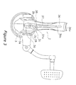
- the casing 2a is formed of a synthetic resin and is produced by injection molding. As shown in Figure 3, the casing 2a has a space which can accommodate various mechanisms therein, and a handle support portion 28 on which the handle 1 can be mounted.
- the lid portion 2b is made of a synthetic resin and is produced by injection molding. As shown in Figure 3, the lid portion 2b has a handle support portion 28 on which the handle 1 can be mounted.
- the rod attachment leg 36 is formed integrally with the lid portion 2b, and is a T-shaped member that extends diagonally upward from the lid portion 2b. As shown in Figure 2, the rod attachment leg 36 is a solid and thick-walled member, one end of which extends longitudinally to form an attachment portion 36a.
- the rod attachment leg 36 has an accommodation space 36b that opens longitudinally along the length thereof, and a reinforcing member 37 is mounted in this accommodation space 36b.
- the reinforcing member 37 is a metal member that is mounted such that a portion thereof protrudes from the outer peripheral surfaces of the rod attachment leg 36.
- a through hole 37a is formed in the lower portion of the reinforcing member 37, and a screw 38 is inserted into the through hole 37a and the lid portion 2b and screwed fast to the casing 2a.
- the reinforcing member 37 is fixedly coupled to the casing 2a.
- the reinforcing member 37 and the screw 38 are conventional components well known in the art. Therefore, the structure of the reinforcing member 37 and the screw 38 will not be discussed or illustrated in detail herein. Also, the reinforcing member 37 can be fixedly coupled to the casing 2a by any other means other than a screw.
- the accommodation space 36b is formed to be open to the exterior of the rod attachment leg 36, and the reinforcing member 37 is mounted in the accommodation space 36b from the opening therein. After attaching the lid portion 2b to the casing 2a, the reinforcing member 37 can be mounted in the accommodation space 36b from the opening in the rod attachment leg 36.
- the strength of the rod attachment leg 36 can be easily increased and maintained with an inexpensive structure.
- the shapes of the reinforcing members and the accommodation spaces are not limited to those shown in the forgoing embodiments.
- the strength of a rod attachment leg on a reel unit of a spinning reel can be easily increased and maintained with an inexpensive structure by forming an accommodation space therein that opens to the exterior of the rod attachment leg, and mounting a reinforcing member in the accommodation space from the opening.
Landscapes
- Life Sciences & Earth Sciences (AREA)
- Environmental Sciences (AREA)
- Animal Husbandry (AREA)
- Biodiversity & Conservation Biology (AREA)
- Storage Of Web-Like Or Filamentary Materials (AREA)
- Magnetic Heads (AREA)
- Fishing Rods (AREA)
Abstract
Description
- This invention generally relates to a reel unit. More specifically, the present invention relates to a reel unit for a spinning reel.
- A spinning reel generally includes a reel unit having a handle, a spool that is mounted on the reel unit so as to be front and rear and on the outer periphery of which fishing line is wound, a rotor supported on the reel unit so as to be freely rotatable thereon and which serves to wind fishing line around the spool, and a rotor drive mechanism that transmits the rotation of the handle to the rotor. The reel unit is formed from a single synthetic resin or metal, and includes a reel body and a T-shaped rod attachment leg which extends diagonally upward from the reel body so as to be integral therewith.
- With this type of spinning reel, it is well known to insert-mold a core in the rod attachment leg due to the fact that a great deal of force (torque) is applied to the rod attachment leg when the fishing line is wound up. An example of this is shown in Japanese Unexamined Patent Application H11-346610.
- In conventional spinning reels, the strength of the rod attachment leg can be increased and maintained because a core is insert-molded in the rod attachment leg. However, because the process of insert-molding the core in the rod attachment leg is complex, there are concerns that the formation of the rod attachment leg is too problematic and that manufacturing costs will increase.
- In view of the above, there exists a need for reel unit which overcomes the above mentioned problems in the prior art. This invention addresses this need in the prior art as well as other needs, which will become apparent to those skilled in the art from this disclosure.
- It is a purpose of the present invention to easily increase and maintain the strength of a rod attachment leg on a reel unit of a spinning reel with an inexpensive structure.
- A reel unit for a spinning reel according to the first aspect of the invention comprises a reel body in which various mechanisms are mounted therein, a T-shaped rod attachment leg portion which extends upward from the reel body and integral therewith and which has an accommodation space that opens to the exterior thereof, and a reinforcing member that is mounted in the accommodation space from the opening.
- In this reel unit, the accommodation space is formed to open to the exterior of the reel body, and the reinforcing member is mounted in the accommodation space from the opening therein. Compared to situations in which a core is insert molded in the rod attachment leg, the strength of the rod attachment leg can be easily increased and maintained with an inexpensive structure because a reinforcing member can be mounted in the accommodation space from the opening after the process which forms the rod attachment leg.
- The reel unit according to the second aspect of the invention is the reel unit of the first aspect, in which the rod attachment leg portion is formed from a synthetic resin. In this situation, the rod attachment leg portion is a portion that will come into direct contact with one's hand, and will have an excellent tactile sensation because it is formed from a synthetic resin.
- The reel unit according to the third aspect of the invention is the reel unit of the first or the second aspect, in which the reinforcing member is formed from a metal. In this situation, the reinforcing effect will be outstanding.
- The reel unit according to the fourth aspect of the invention is the reel unit of the first or the second aspect, in which the reinforcing member is formed from a synthetic resin. In this situation, the reinforcing member can be lightened.
- The reel unit according to the fifth aspect of the invention is the reel unit of any one of claims first through fourth aspects, in which an opening is formed in at least a front side or a rear side of the rod attachment leg portion. In this situation, the rod attachment leg portion can be reinforced particularly with respect to torque by, for example, mounting the reinforcing member from a slit shaped opening formed in the rod attachment leg in the longitudinal direction.
- The reel unit according to the sixth aspect of the invention is the reel unit of any one of first through fifth aspects, in which the reinforcing member is mounted in the accommodation space such that a portion thereof protrudes out therefrom. In this situation, it will be difficult to increase the thickness of the overall rod attachment leg portion because a portion of the reinforcing member is made to protrude out from the peripheral surface thereof.
- The reel unit according to the seventh aspect of the invention is the reel unit of any one of the first through sixth aspects, in which openings are formed at a plurality of positions on the rod attachment leg, and a plurality of reinforcing members are mounted in the accommodation space from the plurality of openings. In this situation, the strength of the rod attachment leg can be further increased and maintained by means of a plurality of reinforcing members.
- The reel unit according to the eighth aspect is the reel unit of any one of the first through seventh aspects, in which the reinforcing member is detachably mounted in the accommodation space. In this situation, the reinforcing member is easily replaced because it can be attached to the rod attachment leg and detached therefrom by means of a screw.
- The reel unit according to the ninth aspect of the invention is the reel unit of the eighth aspect, in which the reel body further comprises a body member in which various mechanisms are mounted therein, and a lid member that is screwed to the body member together with the reinforcing member. In this situation, the number of parts can be reduced by having the screw for the lid member also serve as the screw for the reinforcing member.
- The reel unit according to the tenth aspect of the invention, is the reel unit of the ninth aspect, in which the rod attachment leg portion is formed integral with the body member. In this situation, the structure of the lid member is simplified because the rod attachment leg and the body member are formed integral with each other.
- The reel unit according to the eleventh aspect of the invention, is the reel unit of the ninth aspect, in which the rod attachment leg portion is formed integral with the lid member. In this situation, the rod attachment leg portion and the lid member are integral, and the commingling of the thick portions and thin portions thereof is reduced so that the body member is made thin to increase and maintain the precision thereof, and the rod attachment leg portion is made thick to maintain the strength thereof.
- These and other objects, features, aspects and advantages of the present invention will become apparent to those skilled in the art from the following detailed description, which, taken in conjunction with the annexed drawings, discloses a preferred embodiment of the present invention.
- Referring now to the attached drawings which form a part of this original disclosure:
- Figure 1 is a lateral view of a spinning reel according to an embodiment of the present invention;
- Figure 2 is a cross-sectional view of an attachment leg according to the embodiment of the present invention;
- Figure 3 is a bottom view of the spinning reel according to the embodiment of the present invention;
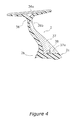
- Figure 4 is a cross-sectional view of an attachment leg corresponding to Figure 2, according to another embodiment of the present invention; and
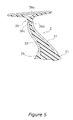
- Figure 5 is a cross-sectional view of an attachment leg corresponding to Figure 2, according to still another embodiment of the present invention.
-
- Selected embodiments of the present invention will now be explained with reference to the drawings. It will be apparent to those skilled in the art from this disclosure that the following description of the embodiments of the present invention is provided for illustration only, and not for the purpose of limiting the invention as defined by the appended claims and their equivalents.
- As shown in Figures 1 and 2, a spinning reel in accordance with an embodiment of the present invention includes a
reel unit 2 rotatably supporting a freelyrotatable handle 1 and mounted to a fishing rod, arotor 3, and a spool 4. Therotor 3 serves to wind a fishing line around the spool 4, and is supported on the front of thereel unit 2 such that it is freely rotatable. The spool 4 is disposed on the front of therotor 3 and can freely move forward and backward so that fishing line is wound around the outer peripheral surface thereof by therotor 3. It should be noted that thehandle 1 can be mounted to the left side of thereel unit 2 as shown in Figure 1, or to the right side of thereel unit 2 as shown in Figure 2. - As shown in Figures 1 and 3, the
reel unit 2 includes areel body 2c that has a casing 2a that supports therotor 3 and the spool 4, and alid portion 2b that is detachably screwed to the casing 2a. Thereel unit 2 further includes a rod attachment leg 36.which extends diagonally upward from thereel body 2c. - As shown in Figures 1 and 3, the casing 2a is formed of a synthetic resin and is produced by injection molding. As shown in Figure 3, the casing 2a has a space which can accommodate various mechanisms therein, and a
handle support portion 28 on which thehandle 1 can be mounted. - As shown in Figures 1 and 3, the
lid portion 2b is made of a synthetic resin and is produced by injection molding. As shown in Figure 3, thelid portion 2b has ahandle support portion 28 on which thehandle 1 can be mounted. - The
rod attachment leg 36 is formed integrally with thelid portion 2b, and is a T-shaped member that extends diagonally upward from thelid portion 2b. As shown in Figure 2, therod attachment leg 36 is a solid and thick-walled member, one end of which extends longitudinally to form anattachment portion 36a. Therod attachment leg 36 has anaccommodation space 36b that opens longitudinally along the length thereof, and a reinforcingmember 37 is mounted in thisaccommodation space 36b. - The reinforcing
member 37 is a metal member that is mounted such that a portion thereof protrudes from the outer peripheral surfaces of therod attachment leg 36. A throughhole 37a is formed in the lower portion of the reinforcingmember 37, and ascrew 38 is inserted into the throughhole 37a and thelid portion 2b and screwed fast to the casing 2a. In this manner, the reinforcingmember 37 is fixedly coupled to the casing 2a. The reinforcingmember 37 and thescrew 38 are conventional components well known in the art. Therefore, the structure of the reinforcingmember 37 and thescrew 38 will not be discussed or illustrated in detail herein. Also, the reinforcingmember 37 can be fixedly coupled to the casing 2a by any other means other than a screw. - In a spinning reel constructed in this manner, the
accommodation space 36b is formed to be open to the exterior of therod attachment leg 36, and the reinforcingmember 37 is mounted in theaccommodation space 36b from the opening therein. After attaching thelid portion 2b to the casing 2a, the reinforcingmember 37 can be mounted in theaccommodation space 36b from the opening in therod attachment leg 36. Thus, compared to situations in which a core is insert-molded in therod attachment leg 36, the strength of therod attachment leg 36 can be easily increased and maintained with an inexpensive structure. -
- (a) The type of spinning reels to which the present invention can be applied is not limited to the aforementioned embodiment. The present invention can be suitably applied to spinning reels having a drag mechanism or a control mechanism that has a brake lever instead of a reverse rotation prevention mechanism.
- (b) Although the reinforcing
member 37 is formed from metal in the aforementioned embodiment, it may also be formed from a synthetic resin. For example, the reinforcingmember 37 may be formed from a synthetic resin that is strengthened with fibers such as glass fibers, carbon fibers, boron, or the like, or a thermoset resin such as an epoxy resin. In addition, although therod attachment leg 36 is formed from a synthetic resin, it may be formed from a metal. - (c) Although the
rod attachment leg 36 in the aforementioned embodiment is formed integrally with thelid portion 2b, therod attachment leg 36 may instead be formed integrally with the casing 2a. - (d) Although the
rod attachment leg 36 in the present embodiment is provided with theaccommodation space 36b that opens longitudinally along the length thereof, theaccommodation space 36b may, for example, be open only along the rear side thereof as shown in Figure 4. - (e) Although the reinforcing
member 37 in the aforementioned embodiments is mounted so that a portion thereof protrudes from the outer peripheral surface of therod attachment leg 36, it may instead be mounted so that it is flush with the outer peripheral surface of therod attachment leg 36 as shown in Figure 4. - (f) Although a single reinforcing
member 37 is mounted in the aforementioned embodiment, as shown in Figure 5, a plurality of reinforcingmembers 37 may be mounted in a plurality ofaccommodation spaces rod attachment leg 36. -
- Furthermore, the shapes of the reinforcing members and the accommodation spaces are not limited to those shown in the forgoing embodiments.
- According to the present invention, the strength of a rod attachment leg on a reel unit of a spinning reel can be easily increased and maintained with an inexpensive structure by forming an accommodation space therein that opens to the exterior of the rod attachment leg, and mounting a reinforcing member in the accommodation space from the opening.
- As used herein, the following directional terms "forward," "rearward," "above," "downward," "vertical," "horizontal," "below" and "transverse" as well as any other similar directional terms refer to those directions of a device equipped with the present invention. Accordingly, these terms, as utilized to describe the present invention should be interpreted relative to a device equipped with the present invention.
- The terms of degree such as "substantially," "about" and "approximately" as used herein mean a reasonable amount of deviation of the modified term such that the end result is not significantly changed. These terms should be construed as including a deviation of at least ± 5% of the modified term if this deviation would not negate the meaning of the word it modifies.
- This application claims priority to Japanese Patent Application No. 2002-223037. The entire disclosure of Japanese Patent Application No. 2002-223037 is hereby incorporated herein by reference.
- While only selected embodiments have been chosen to illustrate the present invention, it will be apparent to those skilled in the art from this disclosure that various changes and modifications can be made herein without departing from the scope of the invention as defined in the appended claims. Furthermore, the foregoing description of the embodiments according to the present invention are provided for illustration only, and not for the purpose of limiting the invention as defined by the appended claims and their equivalents.
Claims (12)
- A reel unit (2) for a spinning reel that is adapted to be attached to a fishing rod and wind out fishing line, the reel unit comprising:a reel body (2c);a T-shaped rod attachment leg portion (36) which extends upward from said reel body, said rod attachment leg portion being formed integrally with a portion of said reel body, and having therein an accommodation space (36b) that opens to an exterior; anda reinforcing member (37) that is coupled to said reel body by being mounted in said accommodation space through said opening.
- The reel unit set forth in Claim 1, wherein said rod attachment leg portion (36) is formed from a synthetic resin.
- The reel unit set forth in claims 1 or 2, wherein said reinforcing member (37)is formed from a metal.
- The reel unit set fourth in Claims 1 or 2, wherein said reinforcing member (37) is formed from a synthetic resin.
- The reel unit set fourth in any preceding Claim, wherein said accommodation space (36b) opens to at least on one of rear side and front side of said rod attachment leg portion (36).
- The reel unit set forth in any preceding Claim, wherein a portion of said reinforcing member (37) protrudes out from said rod attachment leg portion (36) when said reinforcing member is mounted in said accommodation space (36b).
- The reel unit set forth in any preceding Claim, wherein said accommodation space (36b) opens at a plurality of positions (36c, 36d) on said rod attachment leg portion (36); and
said reinforcing member (37) includes a plurality of reinforcing parts that are mounted in said accommodation space from said plurality of openings. - The reel unit set forth in any preceding Claim, wherein said reinforcing member (37) is detachably mounted in said accommodation space (36b).
- The reel unit set forth in any preceding Claim, wherein said reel body further includes a body member (2c), and a lid member (2b) that is coupled to said body member together with said reinforcing member (37).
- The reel unit set forth in Claim 9, wherein said rod attachment leg portion (36) is formed integrally with said body member (2c).
- The reel unit set forth in claim 9, wherein said rod attachment leg portion (36)is formed integrally with said lid member (2b).
- A spinning reel, comprising:a reel unit (2) set forth in any of Claims 1 to 11;a handle (1) supported by said reel unit so as to be freely rotatable;a rotor (3) supported on a front of said reel unit; anda spool (4) disposed on a front of said rotor so as to be movable forward and backward, said spool being for winding a fishing line around said spool.
Applications Claiming Priority (2)
| Application Number | Priority Date | Filing Date | Title |
|---|---|---|---|
| JP2002223037 | 2002-07-31 | ||
| JP2002223037A JP4015901B2 (en) | 2002-07-31 | 2002-07-31 | Spinning reel body |
Publications (2)
| Publication Number | Publication Date |
|---|---|
| EP1386537A1 true EP1386537A1 (en) | 2004-02-04 |
| EP1386537B1 EP1386537B1 (en) | 2007-12-26 |
Family
ID=30112957
Family Applications (1)
| Application Number | Title | Priority Date | Filing Date |
|---|---|---|---|
| EP03253759A Expired - Lifetime EP1386537B1 (en) | 2002-07-31 | 2003-06-13 | Reel unit for spinning reel |
Country Status (9)
| Country | Link |
|---|---|
| US (1) | US7051967B2 (en) |
| EP (1) | EP1386537B1 (en) |
| JP (1) | JP4015901B2 (en) |
| KR (1) | KR100952706B1 (en) |
| CN (1) | CN1324958C (en) |
| AT (1) | ATE381888T1 (en) |
| DE (1) | DE60318279T2 (en) |
| SG (1) | SG128441A1 (en) |
| TW (1) | TWI276400B (en) |
Families Citing this family (10)
| Publication number | Priority date | Publication date | Assignee | Title |
|---|---|---|---|---|
| JP4314108B2 (en) * | 2003-08-20 | 2009-08-12 | 株式会社シマノ | Spinning reel |
| USD528185S1 (en) * | 2005-01-26 | 2006-09-12 | Shimano Inc. | Fishing reel leg portion |
| TWD111268S1 (en) * | 2005-01-26 | 2006-06-01 | 島野股份有限公司 | Fishing reel operating handle |
| USD528626S1 (en) * | 2005-01-26 | 2006-09-19 | Shimano Inc. | Fishing reel cover portion |
| USD528627S1 (en) * | 2005-01-26 | 2006-09-19 | Shimano Inc. | Fishing reel handle |
| SG144041A1 (en) * | 2006-12-21 | 2008-07-29 | Shimano Kk | Reel unit of spinning reel |
| US8556068B2 (en) | 2010-05-10 | 2013-10-15 | Flexible Steel Lacing Company | Method and apparatus for tracking conveyor belts |
| AU2013203168A1 (en) | 2012-03-08 | 2013-09-26 | Flexible Steel Lacing Company | Apparatus and method for tracking conveyor belts |
| EP3374296B1 (en) | 2015-11-12 | 2021-10-20 | Flexible Steel Lacing Company | Apparatus and method for tracking conveyor belts |
| JP7735164B2 (en) * | 2021-11-19 | 2025-09-08 | 株式会社シマノ | Spinning reel body |
Citations (2)
| Publication number | Priority date | Publication date | Assignee | Title |
|---|---|---|---|---|
| JPH11346610A (en) * | 1998-06-09 | 1999-12-21 | Shimano Inc | Spinning reel reel body |
| EP1106062A1 (en) * | 1999-12-06 | 2001-06-13 | Brunswick Corporation | Stem cushion grip, and method of assembly, for fishing reel |
Family Cites Families (17)
| Publication number | Priority date | Publication date | Assignee | Title |
|---|---|---|---|---|
| US412479A (en) * | 1889-10-08 | Charles a | ||
| US1860596A (en) * | 1930-02-24 | 1932-05-31 | Tournus Manuf Metallurg | Handgrip |
| US2799457A (en) * | 1953-08-19 | 1957-07-16 | Franz J Martini | Spinning type fishing reel |
| US4019693A (en) * | 1973-12-10 | 1977-04-26 | Jean Lesage | Fishing reel |
| JPS5290496U (en) | 1975-12-26 | 1977-07-06 | ||
| JPS5634999Y2 (en) * | 1978-10-16 | 1981-08-18 | ||
| JPS61173269U (en) | 1985-04-16 | 1986-10-28 | ||
| US4830306A (en) * | 1986-08-25 | 1989-05-16 | Ryobi Ltd. | Fishing reel leg with soft cover |
| US5470754A (en) | 1992-06-01 | 1995-11-28 | The Coca-Cola Company | Method and system for sampling and determining the presence of compounds |
| US5797554A (en) * | 1996-10-09 | 1998-08-25 | Brunswick Corporation | Cushion grip for fishing reel |
| DE19959005A1 (en) | 1999-12-08 | 2001-06-13 | Abb Research Ltd | Method and device for oil-in-water measurement |
| TW518205B (en) * | 2001-02-23 | 2003-01-21 | Shimano Kk | Spool of spinning reel |
| JP3913510B2 (en) * | 2001-10-04 | 2007-05-09 | 株式会社シマノ | Fastening structure for fishing parts |
| JP2003225039A (en) * | 2002-02-05 | 2003-08-12 | Shimano Inc | Spinning reel reel body |
| US20030146324A1 (en) * | 2002-02-06 | 2003-08-07 | Shih-Yuan Yeh | Fishing reel with a replaceable casing |
| JP3746033B2 (en) * | 2002-10-25 | 2006-02-15 | 株式会社シマノ | Spinning reel body |
| US7066419B2 (en) * | 2003-09-10 | 2006-06-27 | Shimano Inc. | Reel unit for spinning reel |
-
2002
- 2002-07-31 JP JP2002223037A patent/JP4015901B2/en not_active Expired - Fee Related
-
2003
- 2003-05-30 SG SG200303074A patent/SG128441A1/en unknown
- 2003-06-02 TW TW092114932A patent/TWI276400B/en not_active IP Right Cessation
- 2003-06-09 US US10/456,678 patent/US7051967B2/en not_active Expired - Fee Related
- 2003-06-13 DE DE60318279T patent/DE60318279T2/en not_active Expired - Lifetime
- 2003-06-13 AT AT03253759T patent/ATE381888T1/en not_active IP Right Cessation
- 2003-06-13 EP EP03253759A patent/EP1386537B1/en not_active Expired - Lifetime
- 2003-07-23 KR KR1020030050623A patent/KR100952706B1/en not_active Expired - Fee Related
- 2003-07-31 CN CNB03152222XA patent/CN1324958C/en not_active Expired - Fee Related
Patent Citations (2)
| Publication number | Priority date | Publication date | Assignee | Title |
|---|---|---|---|---|
| JPH11346610A (en) * | 1998-06-09 | 1999-12-21 | Shimano Inc | Spinning reel reel body |
| EP1106062A1 (en) * | 1999-12-06 | 2001-06-13 | Brunswick Corporation | Stem cushion grip, and method of assembly, for fishing reel |
Non-Patent Citations (1)
| Title |
|---|
| PATENT ABSTRACTS OF JAPAN vol. 2000, no. 03 30 March 2000 (2000-03-30) * |
Also Published As
| Publication number | Publication date |
|---|---|
| JP2004057140A (en) | 2004-02-26 |
| CN1475110A (en) | 2004-02-18 |
| DE60318279D1 (en) | 2008-02-07 |
| CN1324958C (en) | 2007-07-11 |
| DE60318279T2 (en) | 2008-09-25 |
| KR20040012491A (en) | 2004-02-11 |
| JP4015901B2 (en) | 2007-11-28 |
| TW200401608A (en) | 2004-02-01 |
| ATE381888T1 (en) | 2008-01-15 |
| US7051967B2 (en) | 2006-05-30 |
| EP1386537B1 (en) | 2007-12-26 |
| KR100952706B1 (en) | 2010-04-13 |
| TWI276400B (en) | 2007-03-21 |
| US20040021023A1 (en) | 2004-02-05 |
| SG128441A1 (en) | 2007-01-30 |
Similar Documents
| Publication | Publication Date | Title |
|---|---|---|
| EP1304032B1 (en) | Fastening structure for fishing equipment parts | |
| EP1386537B1 (en) | Reel unit for spinning reel | |
| EP1332672B1 (en) | Reel unit for spinning reel | |
| US20060071107A1 (en) | Handle knob and handle assembly for a fishing reel | |
| US6880776B2 (en) | Reel unit for spinning reel | |
| EP2130431B1 (en) | Reciprocating Mechanism for Spinning Reel | |
| EP1514471B1 (en) | Reel unit for spinning reel | |
| US6857587B2 (en) | Worm shaft attachment structure for spinning reel | |
| US6854677B2 (en) | Spinning-reel sounding mechanism | |
| KR101740930B1 (en) | Spinning reel spool | |
| EP3000318B1 (en) | Handle assembly | |
| US20040251362A1 (en) | Reel unit and cover member for a spinning reel | |
| JP4324462B2 (en) | Spinning reel rotor |
Legal Events
| Date | Code | Title | Description |
|---|---|---|---|
| PUAI | Public reference made under article 153(3) epc to a published international application that has entered the european phase |
Free format text: ORIGINAL CODE: 0009012 |
|
| AK | Designated contracting states |
Kind code of ref document: A1 Designated state(s): AT BE BG CH CY CZ DE DK EE ES FI FR GB GR HU IE IT LI LU MC NL PT RO SE SI SK TR |
|
| AX | Request for extension of the european patent |
Extension state: AL LT LV MK |
|
| 17P | Request for examination filed |
Effective date: 20040130 |
|
| AKX | Designation fees paid |
Designated state(s): AT BE BG CH CY CZ DE DK EE ES FI FR GB GR HU IE IT LI LU MC NL PT RO SE SI SK TR |
|
| RAP1 | Party data changed (applicant data changed or rights of an application transferred) |
Owner name: SHIMANO INC. |
|
| 17Q | First examination report despatched |
Effective date: 20060809 |
|
| GRAP | Despatch of communication of intention to grant a patent |
Free format text: ORIGINAL CODE: EPIDOSNIGR1 |
|
| GRAS | Grant fee paid |
Free format text: ORIGINAL CODE: EPIDOSNIGR3 |
|
| GRAA | (expected) grant |
Free format text: ORIGINAL CODE: 0009210 |
|
| AK | Designated contracting states |
Kind code of ref document: B1 Designated state(s): AT BE BG CH CY CZ DE DK EE ES FI FR GB GR HU IE IT LI LU MC NL PT RO SE SI SK TR |
|
| REG | Reference to a national code |
Ref country code: GB Ref legal event code: FG4D |
|
| REG | Reference to a national code |
Ref country code: IE Ref legal event code: FG4D |
|
| REG | Reference to a national code |
Ref country code: CH Ref legal event code: EP |
|
| REF | Corresponds to: |
Ref document number: 60318279 Country of ref document: DE Date of ref document: 20080207 Kind code of ref document: P |
|
| PG25 | Lapsed in a contracting state [announced via postgrant information from national office to epo] |
Ref country code: SE Free format text: LAPSE BECAUSE OF FAILURE TO SUBMIT A TRANSLATION OF THE DESCRIPTION OR TO PAY THE FEE WITHIN THE PRESCRIBED TIME-LIMIT Effective date: 20080326 Ref country code: LI Free format text: LAPSE BECAUSE OF FAILURE TO SUBMIT A TRANSLATION OF THE DESCRIPTION OR TO PAY THE FEE WITHIN THE PRESCRIBED TIME-LIMIT Effective date: 20071226 Ref country code: CH Free format text: LAPSE BECAUSE OF FAILURE TO SUBMIT A TRANSLATION OF THE DESCRIPTION OR TO PAY THE FEE WITHIN THE PRESCRIBED TIME-LIMIT Effective date: 20071226 |
|
| PG25 | Lapsed in a contracting state [announced via postgrant information from national office to epo] |
Ref country code: SI Free format text: LAPSE BECAUSE OF FAILURE TO SUBMIT A TRANSLATION OF THE DESCRIPTION OR TO PAY THE FEE WITHIN THE PRESCRIBED TIME-LIMIT Effective date: 20071226 Ref country code: FI Free format text: LAPSE BECAUSE OF FAILURE TO SUBMIT A TRANSLATION OF THE DESCRIPTION OR TO PAY THE FEE WITHIN THE PRESCRIBED TIME-LIMIT Effective date: 20071226 Ref country code: NL Free format text: LAPSE BECAUSE OF FAILURE TO SUBMIT A TRANSLATION OF THE DESCRIPTION OR TO PAY THE FEE WITHIN THE PRESCRIBED TIME-LIMIT Effective date: 20071226 |
|
| NLV1 | Nl: lapsed or annulled due to failure to fulfill the requirements of art. 29p and 29m of the patents act | ||
| REG | Reference to a national code |
Ref country code: CH Ref legal event code: PL |
|
| PG25 | Lapsed in a contracting state [announced via postgrant information from national office to epo] |
Ref country code: AT Free format text: LAPSE BECAUSE OF FAILURE TO SUBMIT A TRANSLATION OF THE DESCRIPTION OR TO PAY THE FEE WITHIN THE PRESCRIBED TIME-LIMIT Effective date: 20071226 |
|
| PG25 | Lapsed in a contracting state [announced via postgrant information from national office to epo] |
Ref country code: CZ Free format text: LAPSE BECAUSE OF FAILURE TO SUBMIT A TRANSLATION OF THE DESCRIPTION OR TO PAY THE FEE WITHIN THE PRESCRIBED TIME-LIMIT Effective date: 20071226 Ref country code: ES Free format text: LAPSE BECAUSE OF FAILURE TO SUBMIT A TRANSLATION OF THE DESCRIPTION OR TO PAY THE FEE WITHIN THE PRESCRIBED TIME-LIMIT Effective date: 20080406 |
|
| PG25 | Lapsed in a contracting state [announced via postgrant information from national office to epo] |
Ref country code: RO Free format text: LAPSE BECAUSE OF FAILURE TO SUBMIT A TRANSLATION OF THE DESCRIPTION OR TO PAY THE FEE WITHIN THE PRESCRIBED TIME-LIMIT Effective date: 20071226 Ref country code: BE Free format text: LAPSE BECAUSE OF FAILURE TO SUBMIT A TRANSLATION OF THE DESCRIPTION OR TO PAY THE FEE WITHIN THE PRESCRIBED TIME-LIMIT Effective date: 20071226 Ref country code: SK Free format text: LAPSE BECAUSE OF FAILURE TO SUBMIT A TRANSLATION OF THE DESCRIPTION OR TO PAY THE FEE WITHIN THE PRESCRIBED TIME-LIMIT Effective date: 20071226 |
|
| PG25 | Lapsed in a contracting state [announced via postgrant information from national office to epo] |
Ref country code: PT Free format text: LAPSE BECAUSE OF FAILURE TO SUBMIT A TRANSLATION OF THE DESCRIPTION OR TO PAY THE FEE WITHIN THE PRESCRIBED TIME-LIMIT Effective date: 20080526 |
|
| EN | Fr: translation not filed | ||
| PG25 | Lapsed in a contracting state [announced via postgrant information from national office to epo] |
Ref country code: DK Free format text: LAPSE BECAUSE OF FAILURE TO SUBMIT A TRANSLATION OF THE DESCRIPTION OR TO PAY THE FEE WITHIN THE PRESCRIBED TIME-LIMIT Effective date: 20071226 |
|
| PLBE | No opposition filed within time limit |
Free format text: ORIGINAL CODE: 0009261 |
|
| STAA | Information on the status of an ep patent application or granted ep patent |
Free format text: STATUS: NO OPPOSITION FILED WITHIN TIME LIMIT |
|
| 26N | No opposition filed |
Effective date: 20080929 |
|
| PG25 | Lapsed in a contracting state [announced via postgrant information from national office to epo] |
Ref country code: GR Free format text: LAPSE BECAUSE OF FAILURE TO SUBMIT A TRANSLATION OF THE DESCRIPTION OR TO PAY THE FEE WITHIN THE PRESCRIBED TIME-LIMIT Effective date: 20080327 Ref country code: MC Free format text: LAPSE BECAUSE OF NON-PAYMENT OF DUE FEES Effective date: 20080630 |
|
| PG25 | Lapsed in a contracting state [announced via postgrant information from national office to epo] |
Ref country code: BG Free format text: LAPSE BECAUSE OF FAILURE TO SUBMIT A TRANSLATION OF THE DESCRIPTION OR TO PAY THE FEE WITHIN THE PRESCRIBED TIME-LIMIT Effective date: 20080326 Ref country code: IE Free format text: LAPSE BECAUSE OF NON-PAYMENT OF DUE FEES Effective date: 20080613 Ref country code: EE Free format text: LAPSE BECAUSE OF FAILURE TO SUBMIT A TRANSLATION OF THE DESCRIPTION OR TO PAY THE FEE WITHIN THE PRESCRIBED TIME-LIMIT Effective date: 20071226 Ref country code: FR Free format text: LAPSE BECAUSE OF FAILURE TO SUBMIT A TRANSLATION OF THE DESCRIPTION OR TO PAY THE FEE WITHIN THE PRESCRIBED TIME-LIMIT Effective date: 20081017 |
|
| PG25 | Lapsed in a contracting state [announced via postgrant information from national office to epo] |
Ref country code: CY Free format text: LAPSE BECAUSE OF FAILURE TO SUBMIT A TRANSLATION OF THE DESCRIPTION OR TO PAY THE FEE WITHIN THE PRESCRIBED TIME-LIMIT Effective date: 20071226 |
|
| PG25 | Lapsed in a contracting state [announced via postgrant information from national office to epo] |
Ref country code: LU Free format text: LAPSE BECAUSE OF NON-PAYMENT OF DUE FEES Effective date: 20080613 Ref country code: HU Free format text: LAPSE BECAUSE OF FAILURE TO SUBMIT A TRANSLATION OF THE DESCRIPTION OR TO PAY THE FEE WITHIN THE PRESCRIBED TIME-LIMIT Effective date: 20080627 |
|
| PG25 | Lapsed in a contracting state [announced via postgrant information from national office to epo] |
Ref country code: TR Free format text: LAPSE BECAUSE OF FAILURE TO SUBMIT A TRANSLATION OF THE DESCRIPTION OR TO PAY THE FEE WITHIN THE PRESCRIBED TIME-LIMIT Effective date: 20071226 |
|
| PGFP | Annual fee paid to national office [announced via postgrant information from national office to epo] |
Ref country code: GB Payment date: 20100609 Year of fee payment: 8 |
|
| PG25 | Lapsed in a contracting state [announced via postgrant information from national office to epo] |
Ref country code: IT Free format text: LAPSE BECAUSE OF NON-PAYMENT OF DUE FEES Effective date: 20080630 |
|
| PGFP | Annual fee paid to national office [announced via postgrant information from national office to epo] |
Ref country code: DE Payment date: 20110826 Year of fee payment: 9 |
|
| GBPC | Gb: european patent ceased through non-payment of renewal fee |
Effective date: 20110613 |
|
| PG25 | Lapsed in a contracting state [announced via postgrant information from national office to epo] |
Ref country code: GB Free format text: LAPSE BECAUSE OF NON-PAYMENT OF DUE FEES Effective date: 20110613 |
|
| REG | Reference to a national code |
Ref country code: DE Ref legal event code: R119 Ref document number: 60318279 Country of ref document: DE Effective date: 20120103 |
|
| PG25 | Lapsed in a contracting state [announced via postgrant information from national office to epo] |
Ref country code: DE Free format text: LAPSE BECAUSE OF NON-PAYMENT OF DUE FEES Effective date: 20120103 |