EP1385740B1 - Structure de generateur solaire pour satellite comprenant des calages entre panneaux - Google Patents
Structure de generateur solaire pour satellite comprenant des calages entre panneaux Download PDFInfo
- Publication number
- EP1385740B1 EP1385740B1 EP02720077A EP02720077A EP1385740B1 EP 1385740 B1 EP1385740 B1 EP 1385740B1 EP 02720077 A EP02720077 A EP 02720077A EP 02720077 A EP02720077 A EP 02720077A EP 1385740 B1 EP1385740 B1 EP 1385740B1
- Authority
- EP
- European Patent Office
- Prior art keywords
- panels
- rigid
- successive
- disposed
- satellite
- Prior art date
- Legal status (The legal status is an assumption and is not a legal conclusion. Google has not performed a legal analysis and makes no representation as to the accuracy of the status listed.)
- Expired - Lifetime
Links
- 125000006850 spacer group Chemical group 0.000 claims abstract 3
- 230000004907 flux Effects 0.000 claims 1
- 230000000284 resting effect Effects 0.000 description 3
- 238000004519 manufacturing process Methods 0.000 description 2
- 238000003825 pressing Methods 0.000 description 2
- 238000010887 ISOL method Methods 0.000 description 1
- 239000002131 composite material Substances 0.000 description 1
- 238000010276 construction Methods 0.000 description 1
- 230000008878 coupling Effects 0.000 description 1
- 238000010168 coupling process Methods 0.000 description 1
- 238000005859 coupling reaction Methods 0.000 description 1
- 238000009826 distribution Methods 0.000 description 1
- 239000013013 elastic material Substances 0.000 description 1
- 239000007769 metal material Substances 0.000 description 1
- 238000000034 method Methods 0.000 description 1
- 238000011084 recovery Methods 0.000 description 1
Images

Classifications
-
- B—PERFORMING OPERATIONS; TRANSPORTING
- B64—AIRCRAFT; AVIATION; COSMONAUTICS
- B64G—COSMONAUTICS; VEHICLES OR EQUIPMENT THEREFOR
- B64G1/00—Cosmonautic vehicles
- B64G1/22—Parts of, or equipment specially adapted for fitting in or to, cosmonautic vehicles
- B64G1/42—Arrangements or adaptations of power supply systems
- B64G1/44—Arrangements or adaptations of power supply systems using radiation, e.g. deployable solar arrays
- B64G1/443—Photovoltaic cell arrays
-
- H—ELECTRICITY
- H02—GENERATION; CONVERSION OR DISTRIBUTION OF ELECTRIC POWER
- H02S—GENERATION OF ELECTRIC POWER BY CONVERSION OF INFRARED RADIATION, VISIBLE LIGHT OR ULTRAVIOLET LIGHT, e.g. USING PHOTOVOLTAIC [PV] MODULES
- H02S30/00—Structural details of PV modules other than those related to light conversion
- H02S30/20—Collapsible or foldable PV modules
-
- B—PERFORMING OPERATIONS; TRANSPORTING
- B64—AIRCRAFT; AVIATION; COSMONAUTICS
- B64G—COSMONAUTICS; VEHICLES OR EQUIPMENT THEREFOR
- B64G1/00—Cosmonautic vehicles
- B64G1/22—Parts of, or equipment specially adapted for fitting in or to, cosmonautic vehicles
- B64G1/222—Parts of, or equipment specially adapted for fitting in or to, cosmonautic vehicles for deploying structures between a stowed and deployed state
- B64G1/2221—Parts of, or equipment specially adapted for fitting in or to, cosmonautic vehicles for deploying structures between a stowed and deployed state characterised by the manner of deployment
- B64G1/2222—Folding
- B64G1/2224—Folding about multiple axes
-
- B—PERFORMING OPERATIONS; TRANSPORTING
- B64—AIRCRAFT; AVIATION; COSMONAUTICS
- B64G—COSMONAUTICS; VEHICLES OR EQUIPMENT THEREFOR
- B64G1/00—Cosmonautic vehicles
- B64G1/22—Parts of, or equipment specially adapted for fitting in or to, cosmonautic vehicles
- B64G1/222—Parts of, or equipment specially adapted for fitting in or to, cosmonautic vehicles for deploying structures between a stowed and deployed state
- B64G1/2228—Parts of, or equipment specially adapted for fitting in or to, cosmonautic vehicles for deploying structures between a stowed and deployed state characterised by the hold-down or release mechanisms
-
- Y—GENERAL TAGGING OF NEW TECHNOLOGICAL DEVELOPMENTS; GENERAL TAGGING OF CROSS-SECTIONAL TECHNOLOGIES SPANNING OVER SEVERAL SECTIONS OF THE IPC; TECHNICAL SUBJECTS COVERED BY FORMER USPC CROSS-REFERENCE ART COLLECTIONS [XRACs] AND DIGESTS
- Y02—TECHNOLOGIES OR APPLICATIONS FOR MITIGATION OR ADAPTATION AGAINST CLIMATE CHANGE
- Y02E—REDUCTION OF GREENHOUSE GAS [GHG] EMISSIONS, RELATED TO ENERGY GENERATION, TRANSMISSION OR DISTRIBUTION
- Y02E10/00—Energy generation through renewable energy sources
- Y02E10/50—Photovoltaic [PV] energy
-
- Y—GENERAL TAGGING OF NEW TECHNOLOGICAL DEVELOPMENTS; GENERAL TAGGING OF CROSS-SECTIONAL TECHNOLOGIES SPANNING OVER SEVERAL SECTIONS OF THE IPC; TECHNICAL SUBJECTS COVERED BY FORMER USPC CROSS-REFERENCE ART COLLECTIONS [XRACs] AND DIGESTS
- Y10—TECHNICAL SUBJECTS COVERED BY FORMER USPC
- Y10S—TECHNICAL SUBJECTS COVERED BY FORMER USPC CROSS-REFERENCE ART COLLECTIONS [XRACs] AND DIGESTS
- Y10S136/00—Batteries: thermoelectric and photoelectric
- Y10S136/291—Applications
- Y10S136/292—Space - satellite
Definitions
- the invention relates to a solar satellite generator structure comprising several solar panels each having a flat surface, said panels being superposed in said structure, said structure comprising at least a rod holding said panels compressed to each other, two panels successive contacts being in contact via supports disposed on the periphery of said panels.
- the invention relates to solar generator structures for supporting photovoltaic panels superimposed during a launch phase of the satellite and then deploy these panels to form a generator having for example all its panels positioned in the same plane.
- the need to increase power of such generators leads for example to use cells high-performance photovoltaic panels which are installed on arranged panels in a traditional structure, which generates significant additional manufacturing costs because high efficiency cells are very expensive.
- This kind of structure and the The panels it contains are usually dimensioned by multidirectional appearing in the launch phase of the satellite, and more particularly, by the different vibratory modes that generates this phase. We typically found in these structures stacking columns that pass through apart from the stack of panels in a direction normal to the plans of panels, and which are intended to keep the panels resting on each other.
- stacking columns consist of several hollow sleeves each solidary of a panel, which form a conduit which is traversed by a rod compressing the bushes resting on each other. These stacking columns are sufficiently away from the edges of the panels so as not to interfere with the kinematics of deployment.
- the object of the invention is to remedy this drawback by proposing a structure to reduce the weight of the panels.
- the subject of the invention is a satellite solar generator structure comprising a plurality of solar panels each having a planar surface, said panels being arranged in superposition in said structure, said structure comprising at least one rod holding said compressed panels to each other others, two successive panels being in contact via supports arranged on the periphery of said panels, characterized in that glued spacings distributed on the surface of the panels are arranged between two successive panels for to improve the contact between two successive panels, so that said structure has a better mechanical strength in the launch phase of said satellite.
- the superposition comprises in alternating two semi-rigid panels and a rigid panel.
- the structure comprises four rigid panels and six semi-rigid panels. With this dimensioning, the solar generator has a significant power while having a footprint reduced.
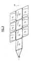
- the structure according to the invention which has been represented in FIG. mainly consisting of a stack of rectangular solar panels substantially forming a parallelepiped.
- This stack includes more especially four rigid panels PR of great thickness, between which are interleaved two to two six semi-rigid PS panels thin.
- These ten panels consist for example of a honeycomb structure supporting a network of photovoltaic cells, are crossed by several stacking columns CG perpendicular to the plane of the panels. These columns are intended for keep the panels clad to each other to encourage the recovery of efforts that are applied to the satellite's launch phase structure.
- each CG stacking column is made up of a plurality of hollow sleeves DO superimposed and resting on each other.
- Each socket is made of metallic or composite material and is integral with a panel corresponding.
- These OD sockets are traversed by a TI rod which compresses the stack of panels by pressing on the sleeves of the top panels and lower of the structure. More particularly, the panels are supported by one compared to the others at the level of hollow bushings OD and non shown in Figure 1 which are arranged at the periphery of each panel.
- this TI rod Prior to the solar generator deployment step, this TI rod is sectioned by example by pyrotechnic process, so that the panels become mechanically released from each other to allow their deployment.
- CA wedges are arranged between the successive panels while being distributed on the surface of the panels, for further increase the mechanical coupling between two successive panels.
- the structure then forms a block able to better take up the efforts appearing in launching course.
- the rigidity of the panels can be reduced, which contributes to improving the power / mass ratio of the whole.
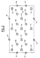
- the CA wedges of the structure according to the invention advantageously distributed evenly over the surface of the panels, to form with the OD sockets and with the AL supports a distribution homogeneous contact points over the entire surface of each panel.
- a panel view is shown in plan view of the structure according to the invention which comprises eight bushes DO, and eight supports AL, in which eleven CA wedges complete these different supports to form a set of contact points homogeneously distributed over the entire surface of the sign.
- the structure according to the invention may have a different number of stacking columns, support, and wedges without departing from the field of the invention.
- the calibration of the CA structure according to the invention are glued for example on the rear face of the panels and press on a corresponding area of the next panel.
- These adjustments are made made of elastic material to better absorb the vibrations, and may be consisting of the stack of a part intended to be glued to one of the panels and a contact portion for pressing the next panel.
- Each part of contact may, depending on the case, press one or more cells or an area of the panel not including cells.
- this structure is able to deploy as the structures of the prior art so that the different panels are positioned in the same plan.
- the rigid panels PR which are integral with the each others unfold to align along an axis of symmetry AX of the generator solar.
- the semi-rigid panels PS are each bound to a rigid panel PR, for deploy laterally to the rigid PR panels.
- the semi-rigid panels PS may be panels reflective, forming an angle with the rigid panels PR, to increase the flow bright perceived by the rigid panels.
- the semi-rigid panels PS will for example be wearing a reflective film, such as films classically used in flow-oriented panel architectures luminous.
Landscapes
- Engineering & Computer Science (AREA)
- Life Sciences & Earth Sciences (AREA)
- Sustainable Development (AREA)
- Remote Sensing (AREA)
- Aviation & Aerospace Engineering (AREA)
- Photovoltaic Devices (AREA)
Description
Claims (4)
- Structure de générateur solaire de satellite comprenant plusieurs panneaux solaires (PR, PS) ayant chacun une surface plane, lesdits panneaux étant disposés en superposition dans ladite structure (ST), ladite structure comprenant au moins une tige (TI) maintenant lesdits panneaux (PR, PS) comprimés les uns aux autres, deux panneaux successifs étant en contact par l'intermédiaire d'appuis (AL) disposés en périphérie desdits panneaux, caractérisée en ce que des calages (CA) sont collés répartis sur la surface des panneaux (PR, PS) et de cette manière sont disposés entre deux panneaux successifs pour améliorer le contact entre deux panneaux successifs, pour que ladite structure présente une meilleure résistance mécaniques en phase de lancement dudit satellite.
- Structure de panneau selon la revendication 1, dans laquelle la superposition comprend en alternance deux panneaux semi-rigides (PS) et un panneau rigide (PR).
- Structure de panneaux selon la revendication 2, comprenant quatre panneaux rigides (PR) et six panneaux semi-rigides (PS).
- Structure de panneau selon la revendication 2 ou 3, dans laquelle lesdits panneaux semi-rigides (PS) sont des panneaux réfléchissants pour augmenter le flux lumineux perçu par les panneaux rigides (PR).
Applications Claiming Priority (3)
| Application Number | Priority Date | Filing Date | Title |
|---|---|---|---|
| FR0104251A FR2822803B1 (fr) | 2001-03-29 | 2001-03-29 | Structure de generateur solaire pour satellite comprenant des calages entre panneaux |
| FR0104251 | 2001-03-29 | ||
| PCT/FR2002/001029 WO2002079034A1 (fr) | 2001-03-29 | 2002-03-25 | Structure de generateur solaire pour satellite comprenant des calages entre panneaux |
Publications (2)
| Publication Number | Publication Date |
|---|---|
| EP1385740A1 EP1385740A1 (fr) | 2004-02-04 |
| EP1385740B1 true EP1385740B1 (fr) | 2004-11-10 |
Family
ID=8861689
Family Applications (1)
| Application Number | Title | Priority Date | Filing Date |
|---|---|---|---|
| EP02720077A Expired - Lifetime EP1385740B1 (fr) | 2001-03-29 | 2002-03-25 | Structure de generateur solaire pour satellite comprenant des calages entre panneaux |
Country Status (7)
| Country | Link |
|---|---|
| US (1) | US6909042B2 (fr) |
| EP (1) | EP1385740B1 (fr) |
| AT (1) | ATE281973T1 (fr) |
| DE (1) | DE60201898T2 (fr) |
| ES (1) | ES2232746T3 (fr) |
| FR (1) | FR2822803B1 (fr) |
| WO (1) | WO2002079034A1 (fr) |
Families Citing this family (19)
| Publication number | Priority date | Publication date | Assignee | Title |
|---|---|---|---|---|
| JP3805706B2 (ja) * | 2002-03-15 | 2006-08-09 | 三菱電機株式会社 | 人工衛星展開構造物 |
| CN100444411C (zh) * | 2007-01-31 | 2008-12-17 | 黄上立 | 可自旋展开的薄膜太阳电池阵及其在太空的应用 |
| US8720125B2 (en) | 2009-07-28 | 2014-05-13 | Micah F. Andretich | Sustainable, mobile, expandable structure |
| FR2969580B1 (fr) * | 2010-12-23 | 2013-08-16 | Thales Sa | Structure deployable formant une antenne equipee d'un generateur solaire pour un satellite |
| US9048530B2 (en) * | 2011-03-09 | 2015-06-02 | Raytheon Company | Deployable flat panel array |
| US8886379B2 (en) | 2013-01-31 | 2014-11-11 | Benjamin David Freeman | Thin safe vehicle whose solar array can supply its power needs |
| DE102014004357A1 (de) * | 2014-03-27 | 2015-10-01 | Airbus Ds Gmbh | Satellitensolargeneratorflügel sowie Satellit |
| JP6693889B2 (ja) | 2014-05-14 | 2020-05-13 | カリフォルニア インスティチュート オブ テクノロジー | 大規模宇宙太陽光発電所:誘導可能ビームを用いる送電 |
| WO2015179213A2 (fr) | 2014-05-14 | 2015-11-26 | California Institute Of Technology | Centrale solaire spatiale de grande échelle : puissance spatiale modulaire multi-échelle |
| EP3149777B1 (fr) | 2014-06-02 | 2024-02-14 | California Institute of Technology | Centrale électrique solaire à base spatiale à grande échelle : tuiles de génération de puissance efficaces |
| US12021162B2 (en) | 2014-06-02 | 2024-06-25 | California Institute Of Technology | Ultralight photovoltaic power generation tiles |
| JP6715317B2 (ja) | 2015-07-22 | 2020-07-01 | カリフォルニア インスティチュート オブ テクノロジー | コンパクトパッケージング用の大面積構造体 |
| JP6500684B2 (ja) * | 2015-07-31 | 2019-04-17 | 日本ゼオン株式会社 | 光電変換装置 |
| US10992253B2 (en) | 2015-08-10 | 2021-04-27 | California Institute Of Technology | Compactable power generation arrays |
| US10454565B2 (en) | 2015-08-10 | 2019-10-22 | California Institute Of Technology | Systems and methods for performing shape estimation using sun sensors in large-scale space-based solar power stations |
| FR3057245B1 (fr) * | 2016-10-06 | 2019-04-05 | Thales Sa | Dispositif de gerbage pour vehicule spatial et vehicule spatial associe |
| US11634240B2 (en) | 2018-07-17 | 2023-04-25 | California Institute Of Technology | Coilable thin-walled longerons and coilable structures implementing longerons and methods for their manufacture and coiling |
| US11772826B2 (en) | 2018-10-31 | 2023-10-03 | California Institute Of Technology | Actively controlled spacecraft deployment mechanism |
| CN112027118A (zh) * | 2020-09-14 | 2020-12-04 | 中国科学院微小卫星创新研究院 | 一种太阳电池阵结构及展开方法 |
Family Cites Families (15)
| Publication number | Priority date | Publication date | Assignee | Title |
|---|---|---|---|---|
| DE3215432C2 (de) * | 1982-04-24 | 1986-10-30 | Messerschmitt-Bölkow-Blohm GmbH, 8000 München | Niederhaltevorrichtung für entfaltbare Solargeneratoren |
| JPS58214500A (ja) * | 1982-06-09 | 1983-12-13 | 三菱電機株式会社 | 人工衛星搭載展開構造物 |
| DE3615263A1 (de) * | 1986-05-06 | 1987-11-12 | Messerschmitt Boelkow Blohm | Niederhaltevorrichtung an raumflugkoerpern |
| FR2657840B1 (fr) * | 1990-02-06 | 1992-05-07 | Aerospatiale | Systeme pour maintenir, en position repliee, un ensemble d'elements deployables sur un engin spatial. |
| FR2669603B2 (fr) * | 1990-06-21 | 1994-10-28 | Aerospatiale | Dispositif articule pour vehicule spatial, notamment pour l'obturation temporaire de l'orifice d'entree d'un instrument optique spatial et sa calibration. |
| FR2722761B1 (fr) * | 1994-07-20 | 1996-09-27 | Aerospatiale | Systeme pour deployer/replier deux elements, avec verrouillage par came desdits elements deployes |
| US5785280A (en) * | 1995-07-20 | 1998-07-28 | Space Systems/Loral, Inc. | Hybrid solar panel array |
| JPH10147298A (ja) * | 1996-11-20 | 1998-06-02 | Mitsubishi Electric Corp | 太陽電池パドル |
| FR2776984B1 (fr) * | 1998-04-06 | 2000-06-16 | Aerospatiale | Dispositif de commande d'une rotation relative entre deux elements articules et structure mecanique deployable, notamment pour vehicule spatial, utilisant au moins un dispositif de ce type |
| EP0977273A1 (fr) * | 1998-07-30 | 2000-02-02 | Hughes Electronics Corporation | Systèmes réflecteurs solaires et méthodes |
| US6168116B1 (en) * | 1999-06-21 | 2001-01-02 | Trw Astro Aerospace | Shear tie device |
| US6177627B1 (en) * | 1999-06-21 | 2001-01-23 | Ace-Able Engineering Co., Inc. | Solar cell array with multiple rows of cells and collapsible reflectors |
| FR2800708B1 (fr) * | 1999-11-04 | 2002-01-25 | Cit Alcatel | Dispositif de maintien et d'amortissement de choc et systeme d'arrimage temporaire d'un element sur une structure, equipe d'un tel dispositif |
| US6484972B1 (en) * | 1999-11-04 | 2002-11-26 | Alcatel | Articulated set of sequentially opened solar generator panels |
| JP3805706B2 (ja) * | 2002-03-15 | 2006-08-09 | 三菱電機株式会社 | 人工衛星展開構造物 |
-
2001
- 2001-03-29 FR FR0104251A patent/FR2822803B1/fr not_active Expired - Fee Related
-
2002
- 2002-03-25 ES ES02720077T patent/ES2232746T3/es not_active Expired - Lifetime
- 2002-03-25 AT AT02720077T patent/ATE281973T1/de not_active IP Right Cessation
- 2002-03-25 US US10/472,865 patent/US6909042B2/en not_active Expired - Lifetime
- 2002-03-25 EP EP02720077A patent/EP1385740B1/fr not_active Expired - Lifetime
- 2002-03-25 DE DE60201898T patent/DE60201898T2/de not_active Expired - Lifetime
- 2002-03-25 WO PCT/FR2002/001029 patent/WO2002079034A1/fr not_active Ceased
Also Published As
| Publication number | Publication date |
|---|---|
| DE60201898T2 (de) | 2005-11-10 |
| WO2002079034A1 (fr) | 2002-10-10 |
| US20040094193A1 (en) | 2004-05-20 |
| ATE281973T1 (de) | 2004-11-15 |
| FR2822803A1 (fr) | 2002-10-04 |
| US6909042B2 (en) | 2005-06-21 |
| DE60201898D1 (de) | 2004-12-16 |
| EP1385740A1 (fr) | 2004-02-04 |
| FR2822803B1 (fr) | 2003-08-15 |
| ES2232746T3 (es) | 2005-06-01 |
Similar Documents
| Publication | Publication Date | Title |
|---|---|---|
| FR2822803A1 (fr) | Structure de generateur solaire pour satellite comprenant des calages entre panneaux | |
| WO2009073995A1 (fr) | Dispositif d'eclairage pour la verification de panneaux photovoltaïques | |
| FR2655204A1 (fr) | Antenne-reseau d'alimentation de guides d'onde. | |
| EP3131746A1 (fr) | Pièce polygonale à alvéoles pour une âme de panneau, en particulier de réflecteur d'antenne de satellite | |
| EP3595007B1 (fr) | Procédé de transfert de structures | |
| WO2006097613A1 (fr) | Dispositif de mesure de force par detection resistive a double pont de wheastone | |
| FR3083918A1 (fr) | Procede de transfert de structures | |
| EP1373071A1 (fr) | Panneau solaire ayant des bornes electriques reparties sur sa surface | |
| WO2020234528A1 (fr) | Structure en treillis | |
| WO2012175835A1 (fr) | Ame de materiau structural feuille et procede d'assemblage | |
| CA3157180C (fr) | Capteur a compensation mecanique de l'anisotropie de frequence | |
| FR2743457A1 (fr) | Moteur piezoelectrique a onde progressive | |
| FR3089695A1 (fr) | Pile à combustible comprenant au moins un organe de traction intégré | |
| EP2847798B1 (fr) | Module photovoltaïque et procédé de realisation d'un tel module | |
| WO2018138425A1 (fr) | Systeme de diffusion sonore | |
| FR2963591A1 (fr) | Pack de batteries electriques et engin motorise comportant au moins un tel pack de batteries | |
| FR3060852A1 (fr) | Dispositif photovoltaique et procede de fabrication associe | |
| EP3203299A1 (fr) | Miroir deformable | |
| EP0176382B1 (fr) | Echangeur de chaleur, en particulier radiateur d'un circuit de refroidissement de moteur de véhicule automobile | |
| FR3114203A1 (fr) | Dispositif ajustable de panneaux solaires | |
| BE1027334B1 (fr) | Ensemble de plaque de cellule pour un compresseur a etat solide, compresseur a etat solide et procede pour faire fonctionner un compresseur a etat solide | |
| FR3036684A1 (fr) | Raidisseur monobloc pour structure aeronautique | |
| EP0495738A1 (fr) | Elément métallique renforcé de poutre télescopique | |
| FR2888037A1 (fr) | Tube photomultiplicateur compact | |
| FR2475299A1 (fr) | Procede de montage d'une diode de protection sur une structure de cellules photovoltaiques multijonctions verticales et cellules photovoltaiques obtenues |
Legal Events
| Date | Code | Title | Description |
|---|---|---|---|
| PUAI | Public reference made under article 153(3) epc to a published international application that has entered the european phase |
Free format text: ORIGINAL CODE: 0009012 |
|
| 17P | Request for examination filed |
Effective date: 20031029 |
|
| AK | Designated contracting states |
Kind code of ref document: A1 Designated state(s): AT BE CH CY DE DK ES FI FR GB GR IE IT LI LU MC NL PT SE TR |
|
| GRAP | Despatch of communication of intention to grant a patent |
Free format text: ORIGINAL CODE: EPIDOSNIGR1 |
|
| GRAS | Grant fee paid |
Free format text: ORIGINAL CODE: EPIDOSNIGR3 |
|
| GRAA | (expected) grant |
Free format text: ORIGINAL CODE: 0009210 |
|
| AK | Designated contracting states |
Kind code of ref document: B1 Designated state(s): AT BE CH CY DE DK ES FI FR GB GR IE IT LI LU MC NL PT SE TR |
|
| PG25 | Lapsed in a contracting state [announced via postgrant information from national office to epo] |
Ref country code: GB Free format text: LAPSE BECAUSE OF FAILURE TO SUBMIT A TRANSLATION OF THE DESCRIPTION OR TO PAY THE FEE WITHIN THE PRESCRIBED TIME-LIMIT Effective date: 20041110 Ref country code: TR Free format text: LAPSE BECAUSE OF FAILURE TO SUBMIT A TRANSLATION OF THE DESCRIPTION OR TO PAY THE FEE WITHIN THE PRESCRIBED TIME-LIMIT Effective date: 20041110 Ref country code: IE Free format text: LAPSE BECAUSE OF FAILURE TO SUBMIT A TRANSLATION OF THE DESCRIPTION OR TO PAY THE FEE WITHIN THE PRESCRIBED TIME-LIMIT Effective date: 20041110 Ref country code: AT Free format text: LAPSE BECAUSE OF FAILURE TO SUBMIT A TRANSLATION OF THE DESCRIPTION OR TO PAY THE FEE WITHIN THE PRESCRIBED TIME-LIMIT Effective date: 20041110 |
|
| REG | Reference to a national code |
Ref country code: GB Ref legal event code: FG4D Free format text: NOT ENGLISH |
|
| REG | Reference to a national code |
Ref country code: CH Ref legal event code: EP |
|
| REG | Reference to a national code |
Ref country code: IE Ref legal event code: FG4D Free format text: FRENCH |
|
| REF | Corresponds to: |
Ref document number: 60201898 Country of ref document: DE Date of ref document: 20041216 Kind code of ref document: P |
|
| PG25 | Lapsed in a contracting state [announced via postgrant information from national office to epo] |
Ref country code: SE Free format text: LAPSE BECAUSE OF FAILURE TO SUBMIT A TRANSLATION OF THE DESCRIPTION OR TO PAY THE FEE WITHIN THE PRESCRIBED TIME-LIMIT Effective date: 20050210 Ref country code: DK Free format text: LAPSE BECAUSE OF FAILURE TO SUBMIT A TRANSLATION OF THE DESCRIPTION OR TO PAY THE FEE WITHIN THE PRESCRIBED TIME-LIMIT Effective date: 20050210 Ref country code: GR Free format text: LAPSE BECAUSE OF FAILURE TO SUBMIT A TRANSLATION OF THE DESCRIPTION OR TO PAY THE FEE WITHIN THE PRESCRIBED TIME-LIMIT Effective date: 20050210 |
|
| PG25 | Lapsed in a contracting state [announced via postgrant information from national office to epo] |
Ref country code: CY Free format text: LAPSE BECAUSE OF FAILURE TO SUBMIT A TRANSLATION OF THE DESCRIPTION OR TO PAY THE FEE WITHIN THE PRESCRIBED TIME-LIMIT Effective date: 20050325 Ref country code: LU Free format text: LAPSE BECAUSE OF NON-PAYMENT OF DUE FEES Effective date: 20050325 |
|
| PG25 | Lapsed in a contracting state [announced via postgrant information from national office to epo] |
Ref country code: BE Free format text: LAPSE BECAUSE OF NON-PAYMENT OF DUE FEES Effective date: 20050331 Ref country code: MC Free format text: LAPSE BECAUSE OF NON-PAYMENT OF DUE FEES Effective date: 20050331 |
|
| REG | Reference to a national code |
Ref country code: ES Ref legal event code: FG2A Ref document number: 2232746 Country of ref document: ES Kind code of ref document: T3 |
|
| GBV | Gb: ep patent (uk) treated as always having been void in accordance with gb section 77(7)/1977 [no translation filed] |
Effective date: 20041110 |
|
| REG | Reference to a national code |
Ref country code: IE Ref legal event code: FD4D |
|
| PLBE | No opposition filed within time limit |
Free format text: ORIGINAL CODE: 0009261 |
|
| STAA | Information on the status of an ep patent application or granted ep patent |
Free format text: STATUS: NO OPPOSITION FILED WITHIN TIME LIMIT |
|
| BERE | Be: lapsed |
Owner name: ALCATEL Effective date: 20050331 |
|
| 26N | No opposition filed |
Effective date: 20050811 |
|
| PG25 | Lapsed in a contracting state [announced via postgrant information from national office to epo] |
Ref country code: CH Free format text: LAPSE BECAUSE OF NON-PAYMENT OF DUE FEES Effective date: 20060331 Ref country code: LI Free format text: LAPSE BECAUSE OF NON-PAYMENT OF DUE FEES Effective date: 20060331 |
|
| REG | Reference to a national code |
Ref country code: CH Ref legal event code: PL |
|
| REG | Reference to a national code |
Ref country code: FR Ref legal event code: CD |
|
| BERE | Be: lapsed |
Owner name: *ALCATEL Effective date: 20050331 |
|
| PG25 | Lapsed in a contracting state [announced via postgrant information from national office to epo] |
Ref country code: PT Free format text: LAPSE BECAUSE OF NON-PAYMENT OF DUE FEES Effective date: 20050410 |
|
| REG | Reference to a national code |
Ref country code: FR Ref legal event code: PLFP Year of fee payment: 15 |
|
| REG | Reference to a national code |
Ref country code: FR Ref legal event code: PLFP Year of fee payment: 16 |
|
| REG | Reference to a national code |
Ref country code: FR Ref legal event code: PLFP Year of fee payment: 17 |
|
| PGFP | Annual fee paid to national office [announced via postgrant information from national office to epo] |
Ref country code: FI Payment date: 20180312 Year of fee payment: 17 |
|
| PGFP | Annual fee paid to national office [announced via postgrant information from national office to epo] |
Ref country code: IT Payment date: 20180321 Year of fee payment: 17 |
|
| PGFP | Annual fee paid to national office [announced via postgrant information from national office to epo] |
Ref country code: ES Payment date: 20180402 Year of fee payment: 17 |
|
| PG25 | Lapsed in a contracting state [announced via postgrant information from national office to epo] |
Ref country code: FI Free format text: LAPSE BECAUSE OF NON-PAYMENT OF DUE FEES Effective date: 20190325 |
|
| PG25 | Lapsed in a contracting state [announced via postgrant information from national office to epo] |
Ref country code: IT Free format text: LAPSE BECAUSE OF NON-PAYMENT OF DUE FEES Effective date: 20190325 |
|
| REG | Reference to a national code |
Ref country code: ES Ref legal event code: FD2A Effective date: 20200728 |
|
| PG25 | Lapsed in a contracting state [announced via postgrant information from national office to epo] |
Ref country code: ES Free format text: LAPSE BECAUSE OF NON-PAYMENT OF DUE FEES Effective date: 20190326 |
|
| PGFP | Annual fee paid to national office [announced via postgrant information from national office to epo] |
Ref country code: NL Payment date: 20210312 Year of fee payment: 20 Ref country code: FR Payment date: 20210225 Year of fee payment: 20 |
|
| PGFP | Annual fee paid to national office [announced via postgrant information from national office to epo] |
Ref country code: DE Payment date: 20210310 Year of fee payment: 20 |
|
| REG | Reference to a national code |
Ref country code: DE Ref legal event code: R071 Ref document number: 60201898 Country of ref document: DE |
|
| REG | Reference to a national code |
Ref country code: NL Ref legal event code: MK Effective date: 20220324 |