EP1385369B1 - Method and installation for producing substrate blocks - Google Patents
Method and installation for producing substrate blocks Download PDFInfo
- Publication number
- EP1385369B1 EP1385369B1 EP02761882A EP02761882A EP1385369B1 EP 1385369 B1 EP1385369 B1 EP 1385369B1 EP 02761882 A EP02761882 A EP 02761882A EP 02761882 A EP02761882 A EP 02761882A EP 1385369 B1 EP1385369 B1 EP 1385369B1
- Authority
- EP
- European Patent Office
- Prior art keywords
- blocks
- infeed
- forming chamber
- installation
- cuttings
- Prior art date
- Legal status (The legal status is an assumption and is not a legal conclusion. Google has not performed a legal analysis and makes no representation as to the accuracy of the status listed.)
- Expired - Lifetime
Links
- 238000000034 method Methods 0.000 title claims abstract description 24
- 239000000758 substrate Substances 0.000 title claims abstract description 23
- 238000009434 installation Methods 0.000 title claims abstract description 16
- 239000000463 material Substances 0.000 claims abstract description 48
- 238000005520 cutting process Methods 0.000 claims abstract description 25
- 239000000654 additive Substances 0.000 claims abstract description 7
- 241000736285 Sphagnum Species 0.000 claims description 14
- 238000007493 shaping process Methods 0.000 claims description 9
- 229940090441 infed Drugs 0.000 claims description 5
- 238000010438 heat treatment Methods 0.000 claims description 3
- 239000004927 clay Substances 0.000 claims description 2
- 235000019362 perlite Nutrition 0.000 claims description 2
- 239000010451 perlite Substances 0.000 claims description 2
- XLYOFNOQVPJJNP-UHFFFAOYSA-N water Substances O XLYOFNOQVPJJNP-UHFFFAOYSA-N 0.000 abstract description 25
- 230000003750 conditioning effect Effects 0.000 abstract description 3
- 235000015097 nutrients Nutrition 0.000 abstract description 3
- 239000013590 bulk material Substances 0.000 description 7
- 230000000694 effects Effects 0.000 description 3
- 238000004382 potting Methods 0.000 description 3
- 238000002347 injection Methods 0.000 description 2
- 239000007924 injection Substances 0.000 description 2
- 238000004519 manufacturing process Methods 0.000 description 2
- 239000002689 soil Substances 0.000 description 2
- 241000255925 Diptera Species 0.000 description 1
- 241000196324 Embryophyta Species 0.000 description 1
- 241001125877 Gobio gobio Species 0.000 description 1
- 230000002745 absorbent Effects 0.000 description 1
- 239000002250 absorbent Substances 0.000 description 1
- 230000015572 biosynthetic process Effects 0.000 description 1
- 230000006835 compression Effects 0.000 description 1
- 238000007906 compression Methods 0.000 description 1
- 238000005755 formation reaction Methods 0.000 description 1
- 239000000417 fungicide Substances 0.000 description 1
- 238000003898 horticulture Methods 0.000 description 1
- 239000007788 liquid Substances 0.000 description 1
- 238000002360 preparation method Methods 0.000 description 1
- 230000001105 regulatory effect Effects 0.000 description 1
- 230000001954 sterilising effect Effects 0.000 description 1
- 238000004659 sterilization and disinfection Methods 0.000 description 1
- 239000000126 substance Substances 0.000 description 1
- 230000008961 swelling Effects 0.000 description 1
- 239000002699 waste material Substances 0.000 description 1
- 238000005303 weighing Methods 0.000 description 1
Images


Classifications
-
- A—HUMAN NECESSITIES
- A01—AGRICULTURE; FORESTRY; ANIMAL HUSBANDRY; HUNTING; TRAPPING; FISHING
- A01G—HORTICULTURE; CULTIVATION OF VEGETABLES, FLOWERS, RICE, FRUIT, VINES, HOPS OR SEAWEED; FORESTRY; WATERING
- A01G24/00—Growth substrates; Culture media; Apparatus or methods therefor
- A01G24/60—Apparatus for preparing growth substrates or culture media
Definitions
- the present invention relates to a method and an installation for producing growth substrate blocks, particularly blocks for cuttings for horticultural use, applying a known basic technique, wherein mainly loose material from a supply of substantially loose substrate material such as sphagnum is fed into a forming chamber for compacting and, subsequently, the material is removed in compacted block or string form for the purpose of forming useable block bodies, if necessary by cutting the block or string formations, which have been formed.
- DE 29 09 488 describes forming of sphagnum blocks in a compression chamber where the sphagnum is transported and compressed by rotating helical screw means. Moisture is added to the sphagnum near the inlet by the end of the rotating helical screw, and moistened sphagnum is compressed and formed. In this way the sphagnum will in the beginning comprise most of the water as droplets without moistening the sphagnum, and first after a relative long time period the sphagnum will become moistened. For that reason this method is ineffective in mass production of plant blocks.
- WO 01/19165 relates to a method and an apparatus for determining the moisture content of bulk material, in particular potting soil, wherein the volume of a quantity of bulk material is determined, the weight of the quantity of bulk material is determined, the specific density is then determined from the volume and the weight, and finally the moisture content is determined by comparison with a table.
- the invention further relates to a method and an apparatus for preparing bulk material, in particular potting soil, with a predetermined moisture content, wherein the volume of a quantity of bulk material is determined, the weight of the quantity of bulk material is determined, and water is then added to the quantity of bulk material until the weight associated with the desired moisture content is obtained.
- the scope of the invention is to achieve a fast and effective preparation and moistening of blocks for cuttings, forming a high number of cutting blocks pr. hour for industrial greenhouse facilities.
- the blocks are both moistened and heated from the inside, so that a moistening process to a desired temperature can take place both quickly and with a minimum of heating energy.
- the moistener which preferably is water, can contain various additives such as nutrients and the like.
- the starting point of the present invention is that it has been found possible to simply and quickly evoke a sufficient moistening of the block material, namely when this takes place in direct continuation of the shaping of the block material as such. It is still imperative that the fed material is loose and relatively dry, but once the material has been compacted it is easily handled when removed in block or string form in wet condition.
- a moistener can be fed to the material in the compacting area during the shaping process, while the material still is loose and willingly is moistened during its movement towards the compacting area and where the moistener in connection with the infeed is distributed in the forming chamber by underpressure.
- a width of air permeable paper is added to the infeed of the loose material, whereby said paper is continuously rounded up in order to created an outer holster around the produced blocks as these are cut off from the formed string.
- the paper width will, thus, surround the passage where the loose material is conveyed to the forming chamber and it will, typically, be near the inner end of this passage that the water is preferably introduced. This is hardly doable through the paper casing, but it has been found fully realistic to convey the water through a pipe or a hose which has been led into the material infeed opening before the infeed area for the paper casing and which extends towards the inside area at the infeed of the forming chamber. There is no need for any special centring or fastening of this water infeed when this ends shortly before the forming chamber, as the infed material thus still can be distributed fairly evenly across the cross section of the formed block material, even though the deposited material now is significantly water carrying.
- the loose infeed material will often be colder than the greenhouse temperature and in this case it will be relevant to use extra heated water, for example at 60-70°C, in order to quickly achieve the desired temperature in the wet blocks. At this or at even higher temperatures a thermal sterilising effect on the material can be achieved and as the material is led directly to the greenhouse, the used heat energy will be regained via the transfer of heat to the air.
- the moistener can contain additives, which cause a chemical sterilisation of the material.
- pricking out holes can take place using already known means in the form of a double piston which is rested against the top of the block, after which the gudgeon pin is activated for a quick down and up shooting in order to form the hole.
- This technique is fully useable regardless of the fact that the blocks are decidedly wet and, as mentioned, is has been found that the holes in the wet material furthermore are particularly form stabile.
- the starting point of the invention is the successive moistening of the block material during the shaping of the blocks
- the derived immediate infeed of the blocks to the greenhouse has shown such great advantages that the invention also will cover this aspect, regardless of whether other methods of moistening are used, for example injection of water or wet steam or a forced application of such in the already shaped blocks.
- the shaping of the blocks per se will thus not be confined to take place in connection to the greenhouse installation.
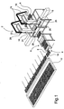
- FIG. 1 In fig. 1 is shown an entire installation for producing moistened growth substrate blocks.
- the installation comprises a fully automatic substrate potting machine 2, a pricking out machine 4 and a transfer unit 6, all connected to a system of conveyer belts 8. From the transfer unit 6 the substrate blocks, which are placed in trays 10, are conveyed to a greenhouse table 12. In an alternative embodiment not shown a further machine for automatic placement of cuttings is comprised.
- a width 16 of air permeable paper is led from a reel 14 to the forming section as such.
- This paper width 16 is formed to an "endless tube", which via vacuum is filled with substrate in the forming chamber 18.
- a hose 20 or a pipe Prior to the area where said paper width 16 is joined to a tube, a hose 20 or a pipe is led into the infeed 22 for the substrate material.
- the moistener in the form of water or steam can be feed to the block, possibly with at an increased temperature and this moistener can, furthermore, contain nutrients, fungicides or other additives which are preferably added in liquid form.
- the area with the forming chamber 18 is shown in more detail, where the infeed pipe 22 for loose substrate material is connected with the forming chamber 18 per se.
- the paper width 16, from which an endless air permeable pipe is formed, is indicated as a "shadow" at the infeed pipe 22 and is formed into a tube surrounding this.
- a hose/pipe 20 for the moistener is led to into the infeed pipe 22.
- the amount of infed moistener is controlled from a not shown control unit which, furthermore, comprises pumps and heating means.
- the infeed of the moistener is, normally, time controlled so that a pump is left running or a valve is opened for a certain amount of time, which thus conveys a measured amount for injection into the substrate block in question.
- the amount of infed moistener is regulated by control weighing of a useable and filled "wet" tray 10, where the weight of this is compared to a useable and filled "dry” tray.
- a forwarding device 24 is indicated, which pulls a new length from the paper pipe forward for filling and, at the same time, pushes the filled paper casing down for cutting at an appropriate height. Subsequently, by using a displaceable dispository unit 26 a whole row of substrate blocks is placed in a suitable tray 10.
- Fig. 3 indicates the profile of the forming chamber 18 and inside this is shown a freely hanging hose 20 through which the moistener is infeed.
- the hose 20 can, in other embodiments of the machine 2, be replaced by a stiff pipe which operates in the same way as the hose 20 shown here.
Landscapes
- Life Sciences & Earth Sciences (AREA)
- Environmental Sciences (AREA)
- Cultivation Receptacles Or Flower-Pots, Or Pots For Seedlings (AREA)
- Cultivation Of Plants (AREA)
- Container, Conveyance, Adherence, Positioning, Of Wafer (AREA)
Abstract
Description
- Fig. 1
- is a situation drawing of an entire installation,
- Fig. 2
- is a partial drawing indicating the area around the forming chamber and
- Fig. 3
- shows the arrangement of infeed hose/pipe for the moistener.
Claims (11)
- Method of producing growth substrate blocks, particularly blocks for cuttings for horticultural use, wherein a loose material from a supply of substantially loose substrate material such as sphagnum is fed into a forming chamber (18) for compacting and, subsequently, the material is removed in compacted string form for the purpose of forming useable block bodies, by cutting the strings into blocks, characterised in that the method comprises a compulsory moistening of the strings with a moisture medium take place, with a heated moisture medium prior to the cutting of the strings into blocks and before the introduction of the blocks into the greenhouse system (12), by establishing an infeed and treatment station from which the blocks successively are fed to the greenhouse system (12) in a number of rows, which preferably pass an in-line mounting area for the cuttings in the blocks, after which these are transported directly to the regular grow area(s) for the cuttings.
- Method according to claim 1, characterised in that a moistener medium is fed to the material in the compacting area during the shaping process, while the material still is loose and willingly is moistened during its movement towards the compacting area, and where the moistener in connection with the infeed is distributed in the block in the forming chamber (18) by underpressure.
- Method according to any of the claims 1-2, characterised in that the infeed of moisture medium takes in place in connection with a vertical inwardly directed infeed of the infeed material to the forming chamber, which equally is vertically oriented and from which the removed block material is led directly into receiving cells in underlying, horizontally conveyed mounting trays (10) for delivery to the greenhouse.
- Method according to any of the claims 1-3, characterised in that the infed moisture medium has a temperature in the interval of between 5°C and 90°C and preferably between 18°C and 70°C.
- Method according to any of the claims 1-4, characterised in that the mounting of the cuttings in prick openings in question is fully automated.
- Method according to any of the claims 1-5, characterised in that particular additives, such as perlite or clay, are added to the substrate material in the block bodies.
- Installation for producing growth substrate blocks according to the method disclosed in claims 1-6, especially for blocks for cutting for horticultural use, wherein the installation from a supply of substantially loose substrate material such as sphagnum is fed loose material in a forming chamber (18) for compacting and subsequent removal of the material in a compacted string form for the purpose of forming useable block bodies by cutting the strings into blocks, characterised in that the installation comprises means (20) for compulsory moistening of strings with a heated moisture medium during the compacting process in the forming chamber.
- Installation according to claim 7, characterised in that it comprises means for heating the moisture medium prior to the infeed of this to the block bodies.
- Installation according to any of the claims 7 and 8, characterised in that the means for compulsory moistening are comprised of a pipe or a hose (20), which has been led into the material infeed pipe (22) prior to the infeed area for an air permeable paper width (16), which surrounds already shaped strings, where said pipe or hose (20) inside the infeed pipe (22) extends to the area at the infeed end (28) of the forming chamber.
- Installation according to any of the claims 7-9, characterised in that means (20) for supplying moisture medium are arranged in connection with a vertical inwardly directed infeed of the infeed material to the forming chamber (18), where the forming chamber (18) is vertically oriented and from which the block material with the use of placing means is led directly into receiving cells in underlying, horizontally conveyed receiving trays (10).
- Installation according to any of the claims 7-10, characterised in that it comprises means for a fully automated mounting of cuttings in the prick openings in the block bodies.
Applications Claiming Priority (3)
| Application Number | Priority Date | Filing Date | Title |
|---|---|---|---|
| DKPA200100610 | 2001-04-11 | ||
| DK200100610 | 2001-04-11 | ||
| PCT/DK2002/000243 WO2002082886A1 (en) | 2001-04-11 | 2002-04-11 | Method and installation for producing substrate blocks |
Publications (2)
| Publication Number | Publication Date |
|---|---|
| EP1385369A1 EP1385369A1 (en) | 2004-02-04 |
| EP1385369B1 true EP1385369B1 (en) | 2004-11-03 |
Family
ID=8160439
Family Applications (1)
| Application Number | Title | Priority Date | Filing Date |
|---|---|---|---|
| EP02761882A Expired - Lifetime EP1385369B1 (en) | 2001-04-11 | 2002-04-11 | Method and installation for producing substrate blocks |
Country Status (6)
| Country | Link |
|---|---|
| US (1) | US7011778B2 (en) |
| EP (1) | EP1385369B1 (en) |
| AT (1) | ATE281065T1 (en) |
| CA (1) | CA2444205A1 (en) |
| DE (1) | DE60201826T2 (en) |
| WO (1) | WO2002082886A1 (en) |
Families Citing this family (3)
| Publication number | Priority date | Publication date | Assignee | Title |
|---|---|---|---|---|
| WO2010028037A2 (en) * | 2008-09-03 | 2010-03-11 | Rynel Inc. | Biopolymer-based growth media, and methods of making and using same |
| CN101704286B (en) * | 2009-11-27 | 2012-10-24 | 陈庆慧 | Method for producing seedling floating plugs |
| DK179090B1 (en) * | 2016-06-17 | 2017-10-23 | Ellepot As | Apparatus and system for transporting a length of growth medium cut into pieces of suitable size into a propagation tray |
Family Cites Families (4)
| Publication number | Priority date | Publication date | Assignee | Title |
|---|---|---|---|---|
| DE2909488C2 (en) * | 1979-03-10 | 1982-04-01 | geb. Schmidt Wilhelmine 4290 Bocholt Mielke | Apparatus for producing sheathed, substantially cylindrical plant pedestals for cuttings |
| FI59240C (en) * | 1979-10-24 | 1981-07-10 | Farmos Oy | OVER ANCHORING FOR OVER PRESSING AV TORV TILL VAEXTSUBSTRATSTYCKEN |
| DK211090D0 (en) * | 1990-09-03 | 1990-09-03 | Oeyvind Ellegaard | METHOD AND PLANT FOR THE MANUFACTURE OF BLOCK MATERIALS FROM LOST MATERIALS, EX. sphagnum |
| NL1013057C2 (en) * | 1999-09-15 | 2001-03-16 | Visser S Gravendeel Holding | Device and method for measuring the moisture level of cultivation substrate such as potting soil. |
-
2002
- 2002-04-11 EP EP02761882A patent/EP1385369B1/en not_active Expired - Lifetime
- 2002-04-11 DE DE60201826T patent/DE60201826T2/en not_active Expired - Fee Related
- 2002-04-11 WO PCT/DK2002/000243 patent/WO2002082886A1/en not_active Ceased
- 2002-04-11 AT AT02761882T patent/ATE281065T1/en not_active IP Right Cessation
- 2002-04-11 US US10/474,365 patent/US7011778B2/en not_active Expired - Fee Related
- 2002-04-11 CA CA002444205A patent/CA2444205A1/en not_active Abandoned
Also Published As
| Publication number | Publication date |
|---|---|
| DE60201826T2 (en) | 2005-12-08 |
| CA2444205A1 (en) | 2002-10-24 |
| US7011778B2 (en) | 2006-03-14 |
| WO2002082886A1 (en) | 2002-10-24 |
| ATE281065T1 (en) | 2004-11-15 |
| EP1385369A1 (en) | 2004-02-04 |
| DE60201826D1 (en) | 2004-12-09 |
| US20040250701A1 (en) | 2004-12-16 |
Similar Documents
| Publication | Publication Date | Title |
|---|---|---|
| KR101313828B1 (en) | Plant growing assembly | |
| US5212906A (en) | Liquid culture apparatus | |
| JP2011515103A (en) | Hydroponic plant growing system using activated carbon fiber and / or carbonized fiber substrate | |
| AU3742793A (en) | Process and apparatus for planting plantlets | |
| US7011778B2 (en) | Method and installation for producing substrate blocks | |
| DK179595B1 (en) | Process for line production of plant growth medium bags and pots | |
| CN100998300B (en) | Light Matrix Mesh Bag Container Packaging System | |
| KR20040045564A (en) | Method for cultivating pear | |
| KR20230087563A (en) | Hydroponics systems, and processes for manufacturing hydroponic systems | |
| JPH0349628A (en) | Nutritive solution cultivation bed and nutritive solution cultivation using the same | |
| CN120753132B (en) | Non-woven fabric light matrix deep root seedling raising method | |
| RU214491U1 (en) | Pressed sphagnum moss briquette | |
| KR20220129042A (en) | Systems for manufacturing hydroponic systems, and hydroponic systems manufactured by such systems | |
| JP2004073054A (en) | Sterilization method and sterilization device for plant cultivation base of plant | |
| CN210694917U (en) | Device for planting organic vegetables in foreign soil pot | |
| JP6101885B1 (en) | Method for producing bark mat for plant cultivation | |
| CN209710867U (en) | Camellia seedling nutrition cup | |
| CN106358798A (en) | Vertical organic farm for efficiently planting peanuts | |
| CN106613498A (en) | Tomato three-dimensional, efficient, organic and green planting bank and planting method of tomatoes | |
| CN120918015A (en) | Aralia elata seem cutting seedling raising device and seedling raising method | |
| CN119111324A (en) | A kind of automatic production and making device of edible fungus cultivation bag | |
| CN116195486A (en) | Device and method for producing big pot for gardening big seedling | |
| AU2002244515B8 (en) | Means and method of generating feed | |
| EP4319544A1 (en) | Apparatus, plant and method for cultivation of beet plants | |
| JPH11168988A (en) | Medium loading device and medium loading method |
Legal Events
| Date | Code | Title | Description |
|---|---|---|---|
| PUAI | Public reference made under article 153(3) epc to a published international application that has entered the european phase |
Free format text: ORIGINAL CODE: 0009012 |
|
| 17P | Request for examination filed |
Effective date: 20031027 |
|
| AK | Designated contracting states |
Kind code of ref document: A1 Designated state(s): AT BE CH CY DE DK ES FI FR GB GR IE IT LI LU MC NL PT SE TR |
|
| AX | Request for extension of the european patent |
Extension state: AL LT LV MK RO SI |
|
| GRAJ | Information related to disapproval of communication of intention to grant by the applicant or resumption of examination proceedings by the epo deleted |
Free format text: ORIGINAL CODE: EPIDOSDIGR1 |
|
| GRAP | Despatch of communication of intention to grant a patent |
Free format text: ORIGINAL CODE: EPIDOSNIGR1 |
|
| GRAS | Grant fee paid |
Free format text: ORIGINAL CODE: EPIDOSNIGR3 |
|
| GRAA | (expected) grant |
Free format text: ORIGINAL CODE: 0009210 |
|
| AK | Designated contracting states |
Kind code of ref document: B1 Designated state(s): AT BE CH CY DE DK ES FI FR GB GR IE IT LI LU MC NL PT SE TR |
|
| PG25 | Lapsed in a contracting state [announced via postgrant information from national office to epo] |
Ref country code: LI Free format text: LAPSE BECAUSE OF FAILURE TO SUBMIT A TRANSLATION OF THE DESCRIPTION OR TO PAY THE FEE WITHIN THE PRESCRIBED TIME-LIMIT Effective date: 20041103 Ref country code: AT Free format text: LAPSE BECAUSE OF FAILURE TO SUBMIT A TRANSLATION OF THE DESCRIPTION OR TO PAY THE FEE WITHIN THE PRESCRIBED TIME-LIMIT Effective date: 20041103 Ref country code: FI Free format text: LAPSE BECAUSE OF FAILURE TO SUBMIT A TRANSLATION OF THE DESCRIPTION OR TO PAY THE FEE WITHIN THE PRESCRIBED TIME-LIMIT Effective date: 20041103 Ref country code: TR Free format text: LAPSE BECAUSE OF FAILURE TO SUBMIT A TRANSLATION OF THE DESCRIPTION OR TO PAY THE FEE WITHIN THE PRESCRIBED TIME-LIMIT Effective date: 20041103 Ref country code: CH Free format text: LAPSE BECAUSE OF FAILURE TO SUBMIT A TRANSLATION OF THE DESCRIPTION OR TO PAY THE FEE WITHIN THE PRESCRIBED TIME-LIMIT Effective date: 20041103 Ref country code: IT Free format text: LAPSE BECAUSE OF FAILURE TO SUBMIT A TRANSLATION OF THE DESCRIPTION OR TO PAY THE FEE WITHIN THE PRESCRIBED TIME-LIMIT;WARNING: LAPSES OF ITALIAN PATENTS WITH EFFECTIVE DATE BEFORE 2007 MAY HAVE OCCURRED AT ANY TIME BEFORE 2007. THE CORRECT EFFECTIVE DATE MAY BE DIFFERENT FROM THE ONE RECORDED. Effective date: 20041103 |
|
| REG | Reference to a national code |
Ref country code: GB Ref legal event code: FG4D |
|
| REG | Reference to a national code |
Ref country code: CH Ref legal event code: EP |
|
| REF | Corresponds to: |
Ref document number: 60201826 Country of ref document: DE Date of ref document: 20041209 Kind code of ref document: P |
|
| REG | Reference to a national code |
Ref country code: IE Ref legal event code: FG4D |
|
| PG25 | Lapsed in a contracting state [announced via postgrant information from national office to epo] |
Ref country code: DK Free format text: LAPSE BECAUSE OF FAILURE TO SUBMIT A TRANSLATION OF THE DESCRIPTION OR TO PAY THE FEE WITHIN THE PRESCRIBED TIME-LIMIT Effective date: 20050203 Ref country code: SE Free format text: LAPSE BECAUSE OF FAILURE TO SUBMIT A TRANSLATION OF THE DESCRIPTION OR TO PAY THE FEE WITHIN THE PRESCRIBED TIME-LIMIT Effective date: 20050203 Ref country code: GR Free format text: LAPSE BECAUSE OF FAILURE TO SUBMIT A TRANSLATION OF THE DESCRIPTION OR TO PAY THE FEE WITHIN THE PRESCRIBED TIME-LIMIT Effective date: 20050203 |
|
| PG25 | Lapsed in a contracting state [announced via postgrant information from national office to epo] |
Ref country code: ES Free format text: LAPSE BECAUSE OF FAILURE TO SUBMIT A TRANSLATION OF THE DESCRIPTION OR TO PAY THE FEE WITHIN THE PRESCRIBED TIME-LIMIT Effective date: 20050214 |
|
| PG25 | Lapsed in a contracting state [announced via postgrant information from national office to epo] |
Ref country code: LU Free format text: LAPSE BECAUSE OF NON-PAYMENT OF DUE FEES Effective date: 20050411 Ref country code: IE Free format text: LAPSE BECAUSE OF NON-PAYMENT OF DUE FEES Effective date: 20050411 Ref country code: CY Free format text: LAPSE BECAUSE OF FAILURE TO SUBMIT A TRANSLATION OF THE DESCRIPTION OR TO PAY THE FEE WITHIN THE PRESCRIBED TIME-LIMIT Effective date: 20050411 |
|
| PG25 | Lapsed in a contracting state [announced via postgrant information from national office to epo] |
Ref country code: MC Free format text: LAPSE BECAUSE OF NON-PAYMENT OF DUE FEES Effective date: 20050430 |
|
| REG | Reference to a national code |
Ref country code: CH Ref legal event code: PL |
|
| PLBE | No opposition filed within time limit |
Free format text: ORIGINAL CODE: 0009261 |
|
| STAA | Information on the status of an ep patent application or granted ep patent |
Free format text: STATUS: NO OPPOSITION FILED WITHIN TIME LIMIT |
|
| ET | Fr: translation filed | ||
| 26N | No opposition filed |
Effective date: 20050804 |
|
| PGFP | Annual fee paid to national office [announced via postgrant information from national office to epo] |
Ref country code: BE Payment date: 20060427 Year of fee payment: 5 |
|
| BERE | Be: lapsed |
Owner name: *ELLEGAARD A/S Effective date: 20070430 |
|
| PG25 | Lapsed in a contracting state [announced via postgrant information from national office to epo] |
Ref country code: PT Free format text: LAPSE BECAUSE OF NON-PAYMENT OF DUE FEES Effective date: 20050403 |
|
| PG25 | Lapsed in a contracting state [announced via postgrant information from national office to epo] |
Ref country code: BE Free format text: LAPSE BECAUSE OF NON-PAYMENT OF DUE FEES Effective date: 20070430 |
|
| PGFP | Annual fee paid to national office [announced via postgrant information from national office to epo] |
Ref country code: DE Payment date: 20090414 Year of fee payment: 8 Ref country code: FR Payment date: 20090331 Year of fee payment: 8 Ref country code: NL Payment date: 20090415 Year of fee payment: 8 |
|
| PGFP | Annual fee paid to national office [announced via postgrant information from national office to epo] |
Ref country code: GB Payment date: 20090414 Year of fee payment: 8 |
|
| REG | Reference to a national code |
Ref country code: NL Ref legal event code: V1 Effective date: 20101101 |
|
| GBPC | Gb: european patent ceased through non-payment of renewal fee |
Effective date: 20100411 |
|
| REG | Reference to a national code |
Ref country code: FR Ref legal event code: ST Effective date: 20101230 |
|
| PG25 | Lapsed in a contracting state [announced via postgrant information from national office to epo] |
Ref country code: NL Free format text: LAPSE BECAUSE OF NON-PAYMENT OF DUE FEES Effective date: 20101101 Ref country code: FR Free format text: LAPSE BECAUSE OF NON-PAYMENT OF DUE FEES Effective date: 20100430 |
|
| PG25 | Lapsed in a contracting state [announced via postgrant information from national office to epo] |
Ref country code: DE Free format text: LAPSE BECAUSE OF NON-PAYMENT OF DUE FEES Effective date: 20101103 |
|
| PG25 | Lapsed in a contracting state [announced via postgrant information from national office to epo] |
Ref country code: GB Free format text: LAPSE BECAUSE OF NON-PAYMENT OF DUE FEES Effective date: 20100411 |