EP1385318A1 - Collapsible cellular communication terminal having a camera having photographing control function and photographing control method in the terminal - Google Patents
Collapsible cellular communication terminal having a camera having photographing control function and photographing control method in the terminal Download PDFInfo
- Publication number
- EP1385318A1 EP1385318A1 EP02707274A EP02707274A EP1385318A1 EP 1385318 A1 EP1385318 A1 EP 1385318A1 EP 02707274 A EP02707274 A EP 02707274A EP 02707274 A EP02707274 A EP 02707274A EP 1385318 A1 EP1385318 A1 EP 1385318A1
- Authority
- EP
- European Patent Office
- Prior art keywords
- mobile communications
- communications terminal
- photographing
- unit
- warning
- Prior art date
- Legal status (The legal status is an assumption and is not a legal conclusion. Google has not performed a legal analysis and makes no representation as to the accuracy of the status listed.)
- Withdrawn
Links
- 238000000034 method Methods 0.000 title claims description 9
- 230000010267 cellular communication Effects 0.000 title 1
- 238000010295 mobile communication Methods 0.000 claims abstract description 81
- 230000006870 function Effects 0.000 description 22
- 238000004891 communication Methods 0.000 description 10
- 238000001514 detection method Methods 0.000 description 9
- 239000000470 constituent Substances 0.000 description 5
- 239000004973 liquid crystal related substance Substances 0.000 description 4
- 239000004065 semiconductor Substances 0.000 description 4
- 230000005236 sound signal Effects 0.000 description 4
- 238000005401 electroluminescence Methods 0.000 description 3
- 238000010586 diagram Methods 0.000 description 2
- 230000004048 modification Effects 0.000 description 2
- 238000012986 modification Methods 0.000 description 2
- 238000006243 chemical reaction Methods 0.000 description 1
- 230000000295 complement effect Effects 0.000 description 1
- 238000010276 construction Methods 0.000 description 1
- 229910044991 metal oxide Inorganic materials 0.000 description 1
- 150000004706 metal oxides Chemical class 0.000 description 1
- 230000004044 response Effects 0.000 description 1
Images


Classifications
-
- H—ELECTRICITY
- H04—ELECTRIC COMMUNICATION TECHNIQUE
- H04B—TRANSMISSION
- H04B1/00—Details of transmission systems, not covered by a single one of groups H04B3/00 - H04B13/00; Details of transmission systems not characterised by the medium used for transmission
- H04B1/38—Transceivers, i.e. devices in which transmitter and receiver form a structural unit and in which at least one part is used for functions of transmitting and receiving
-
- H—ELECTRICITY
- H04—ELECTRIC COMMUNICATION TECHNIQUE
- H04M—TELEPHONIC COMMUNICATION
- H04M1/00—Substation equipment, e.g. for use by subscribers
- H04M1/02—Constructional features of telephone sets
- H04M1/0202—Portable telephone sets, e.g. cordless phones, mobile phones or bar type handsets
- H04M1/0206—Portable telephones comprising a plurality of mechanically joined movable body parts, e.g. hinged housings
- H04M1/0208—Portable telephones comprising a plurality of mechanically joined movable body parts, e.g. hinged housings characterized by the relative motions of the body parts
- H04M1/0214—Foldable telephones, i.e. with body parts pivoting to an open position around an axis parallel to the plane they define in closed position
-
- H—ELECTRICITY
- H04—ELECTRIC COMMUNICATION TECHNIQUE
- H04M—TELEPHONIC COMMUNICATION
- H04M1/00—Substation equipment, e.g. for use by subscribers
- H04M1/02—Constructional features of telephone sets
-
- H—ELECTRICITY
- H04—ELECTRIC COMMUNICATION TECHNIQUE
- H04M—TELEPHONIC COMMUNICATION
- H04M1/00—Substation equipment, e.g. for use by subscribers
- H04M1/02—Constructional features of telephone sets
- H04M1/0202—Portable telephone sets, e.g. cordless phones, mobile phones or bar type handsets
- H04M1/0206—Portable telephones comprising a plurality of mechanically joined movable body parts, e.g. hinged housings
- H04M1/0241—Portable telephones comprising a plurality of mechanically joined movable body parts, e.g. hinged housings using relative motion of the body parts to change the operational status of the telephone set, e.g. switching on/off, answering incoming call
- H04M1/0245—Portable telephones comprising a plurality of mechanically joined movable body parts, e.g. hinged housings using relative motion of the body parts to change the operational status of the telephone set, e.g. switching on/off, answering incoming call using open/close detection
-
- H—ELECTRICITY
- H04—ELECTRIC COMMUNICATION TECHNIQUE
- H04M—TELEPHONIC COMMUNICATION
- H04M2250/00—Details of telephonic subscriber devices
- H04M2250/52—Details of telephonic subscriber devices including functional features of a camera
-
- H—ELECTRICITY
- H04—ELECTRIC COMMUNICATION TECHNIQUE
- H04N—PICTORIAL COMMUNICATION, e.g. TELEVISION
- H04N1/00—Scanning, transmission or reproduction of documents or the like, e.g. facsimile transmission; Details thereof
- H04N1/00127—Connection or combination of a still picture apparatus with another apparatus, e.g. for storage, processing or transmission of still picture signals or of information associated with a still picture
- H04N1/00281—Connection or combination of a still picture apparatus with another apparatus, e.g. for storage, processing or transmission of still picture signals or of information associated with a still picture with a telecommunication apparatus, e.g. a switched network of teleprinters for the distribution of text-based information, a selective call terminal
- H04N1/00307—Connection or combination of a still picture apparatus with another apparatus, e.g. for storage, processing or transmission of still picture signals or of information associated with a still picture with a telecommunication apparatus, e.g. a switched network of teleprinters for the distribution of text-based information, a selective call terminal with a mobile telephone apparatus
Definitions
- the present invention relates to a folding built-in camera mobile communications terminal that has a photographing control function, and a photographing control method used in the terminal.
- to photograph represents a process of forming an image of an object on the surface of a semiconductor photodetector through a lens of a camera and converting the formed image into image data.
- a CCD camera is arranged on the rear side of such built-in camera mobile telephone.
- the object image photographed by the CCD camera is displayed on a liquid crystal screen provided on the front side of the mobile telephone. This enables the user to see the image of the photographed object on the liquid crystal screen on the spot. Furthermore, the user can store the photographed object image in the mobile telephone, or send it to his/her friends and family by email.
- the above object is achieved by a folding mobile communications terminal that has a photographing function and is openable and closable.
- the folding mobile communications terminal includes (i) a detecting unit operable to detect whether the folding mobile communications terminal is in a closed state, and (ii) a photographing control unit operable to disable the photographing function when the detecting unit detects that the folding mobile communications terminal is in the closed state.
- a folding mobile communications terminal that is openable and closable, which is characterized by including (i) a photographic lens that is positioned so as to be externally invisible when the mobile communications terminal is in a closed state, and (ii) a photographing unit operable to photograph an object through the photographic lens.
- the above object is also achieved by a photographing control method for a folding mobile communications terminal that has a photographing function and is openable and closable.
- the photographing control method includes (i) a detecting step of detecting whether the folding mobile communications terminal is in a closed state, and (ii) a photographing control step of disabling the photographing function when detected that the folding mobile communications terminal is in the closed state.
- the above-mentioned constituent features make a photographer unable to perform photographing when the folding mobile communications terminal is in the closed state and thereby in its compact state. It is therefore difficult for the photographer to take photos without being noticed by the people around him/her. As a result, the attempts of taking sneak shots are effectively prevented.
- the detecting unit may further detect an opening angle of the folding mobile communications terminal, and the photographing control unit may further disable the photographing function when the detected opening angle is below a threshold angle.
- the photographing control unit may include a warning unit operable to generate a warning when the detected opening angle is below the threshold angle.
- the photographing control unit may include a warning unit operable to generate a warning when the detecting unit detects that the folding mobile communications terminal is in the closed state.
- the folding mobile communications terminal further includes a lightness judging unit operable to (i) measure lightness which indicates a level of ambient light and (ii) judge whether the lightness is below a threshold level.
- the photographing control unit may further disable the photographing function when the lightness judging unit judges that the lightness is below the threshold level.
- the photographing control unit may include a warning unit operable to generate a warning when the lightness judging unit judges that the lightness is below the threshold level.
- This constituent feature can arouse attention of targets of sneak shots so that they easily notice the vile attempts.
- the folding mobile communications terminal may further include a lightness judging unit operable to (i) measure lightness which indicates a level of ambient light and (ii) judge whether the lightness is below a threshold level.
- the photographing control unit may include a warning unit operable to generate a warning when the lightness judging unit judges that the lightness is below the threshold level.
- the warning unit may generate the warning by emitting light.
- the warning unit may generate the warning by making the folding mobile communications terminal vibrate.
- the warning unit may generate the warning by outputting a voice message.
- a folding mobile communications terminal to which an embodiment of the present invention relates is a folding mobile communications terminal that has a photographing function and is openable and closable. This folding mobile communications terminal detects whether the folds are closed, and disables the photographing function if the folds are closed.
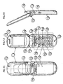
- Fig. 1 shows an external view of a folding mobile communications terminal 1 relating to the present embodiment in the open state, wherein, more specifically, Fig. 1A shows a front view of the folding mobile communications terminal 1, Fig. 1B shows a right side view of the folding mobile communications terminal 1, and Fig. 1C presents a rear view of the folding mobile communications terminal 1.
- the folding mobile communications terminal 1 includes: a subhousing 11; a subhousing 12; a main display unit 13; an operatingunit 36; amicrophone 15; anopen/close statedetecting unit 16; a receiver 17; an earphone terminal 18; an antenna 31; a speaker 20; a sub-display unit 21; a camera unit 22; a hinge unit 23; a mirror 24; and an opening 25.
- the subhousing 11, the subhousing 12, the open/close state detecting unit 16, a side key 14i included in the operating unit 36, the earphone terminal 18, the mirror 24, and the opening 25 are described first, and the other constituents will be described in the later part.
- the subhousing 11 and the subhousing 12 are joined together by means of the hinge unit 23 provided therebetween, to form a foldable housing.
- the main display unit 13 and the receiver 17 are arranged on the inner surface (shown in Fig. 1A) of the subhousing 11.
- the speaker 20 and the sub-display unit 21 are arranged on the outer surface (shown in Fig. 1C) of the subhousing 11.
- the operating unit 36 and the microphone 15 are arranged on the inner surface (shown in Fig. 1A) of the subhousing 12.
- the camera unit 22, the mirror 24, and the opening 25 are arranged on the outer surface (shown in Fig. 1C) of the subhousing 12.
- the side key 14i that functions as a shutter button for performing photographing with the camera unit 22 is arranged on the side of the subhousing 12.
- a photographic lens included in the camera unit 22 is arranged on the surface of the subhousing 12.
- the side key 14i is used to perform photographing with the camera unit 22.
- the side key 14i has two states, namely, halfway pressed and fully pressed.
- a photographing operation start instruction is issued to a control unit 34 (described later).
- a photographing execution instruction is issued.
- the "photographing operation start instruction” is an instruction to have the camera unit 22 start capturing an object image and sequentially display, on the main display unit 13, as image data, the captured object image.
- the "photographing execution instruction” is an instruction to have a memory unit 38 (described later) store an object image that is photographed by the camera unit 22 at the point of the issuance of the photographing execution instruction.
- the open/close state detecting unit 16 is a microswitch that mechanically detects whether the folding mobile communications terminal 1 is in the open state or the closed state. For instance, the detection is performed in the following manner.
- a convex part (indicated by reference numeral 16a in Fig. 1A) is provided on the subhousing 11. If the convex part is pressing down the open/close state detecting unit 16, the open/close state detecting unit 16 mechanically detects that the folding mobile communications terminal 1 is in the closed state, and outputs a detection signal to the control unit 34 (described later). In this way, the control unit 34 can detect that the folding mobile communications terminal 1 is in the closed state.
- the open/close state detecting unit 16 may perform the detection in the following manner.
- a light sensor is provided in the open/close state detecting unit 16. This light sensor generates a voltage according to the quantity of light received by the light sensor through an opening provided on the open/close state detecting unit 16.
- the folding mobile communications terminal 1 is judged as being in the open state if the generated voltage is greater than a threshold voltage that is determined beforehand in connection with the open state, or judged as being in the partly-open state if the generated voltage is no more than the threshold voltage.
- the folding mobile communications terminal 1 is judged as being in the closed state if the generated voltage is below a threshold voltage that is determined beforehand in connection with the closed state.
- the "partly-open state” represents a state in which the folding mobile communications terminal 1 is not completely open, for example, the opening angle between the inner surfaces of the subhousing 11 and subhousing 12 is not more than a predetermined angle, say, 90 degrees.
- the detection may be performed using other known techniques, such as using an encoder to detect the opening angle between the subhousing 11 and the subhousing 12.
- the earphone terminal 18 is used for connecting an earphone microphone to the folding mobile communications terminal 1.
- the mirror 24 is used when a user attempts to take a photo of himself/herself. More specifically, the user can make sure that the photographic lens of the camera unit 22 properly finds himself/herself, by checking whether s/he can see his/her own reflections in the mirror 24.
- the opening 25 lets ambient light in so that a light sensor unit 37 (described later) can detect a level of the ambient light of the subhousing 12(hereinafter referred to as lightness).
- Fig. 2 is a functional block diagram presenting a configuration of the folding mobile communications terminal 1.
- the folding mobile communications terminal 1 includes: the antenna 31; a transmitting/receiving unit 32; a modulating/demodulating unit 33; the control unit 34; the main display unit 13; the sub-display unit 21; the camera unit 22; a camera interface (I/F) 35; the operating unit 36; a voice processing unit 39; the microphone 15; the receiver 17; the light sensor unit 37; and the memory unit 38.
- the antenna 31 transmits and receives radio waves for communication.
- the transmitting/receiving unit 32 transmits and receives data which is communicated via radio waves.
- the communication data includes: sound data of a telephone conversation; character information; image data; control data used to control communication (e.g. information regarding incoming voice communication such as a telephone number of a caller, information regarding incoming emails and text messages that are sent using the Short Message Service (SMS) bearer) and the like.
- SMS Short Message Service
- the modulating/demodulating unit 33 modulates communication data to be transmitted.
- the modulating/demodulating unit 33 also demodulates received communication data, and outputs it to the voice processing unit 39.
- the control unit 34 includes, for example, a microprocessor, a Read Only Memory (ROM) 34a, andaRandomAccess Memory (RAM) 34b.
- the control unit 34 performs various kinds of control such as photographing control, according to a control program stored in the ROM 34a. More specifically, the control unit 34 performs the photographing control based on: the user's instruction concerning photographing (a photographing operation start instruction or a photographing execution instruction) inputted via the side key 14i; a detection signal outputted from the open/close state detecting unit 16; and a voltage which is outputted from the light sensor unit 37.
- the control unit 34 receives the photographing execution instruction, the control unit 34 reads, from the RAM 34b, image data of a captured object image and stores the image data in the memory unit 38.
- the ROM 34a stores the control program mentioned above and a threshold voltage which is compared with the voltage outputted from the light sensor unit 37.
- the RAM 34b stores communication data received and to be transmitted; image data of a captured obj ect image, phonebook data (for example, 999 memory dial entries) and the like, temporarily or until the user erases or changes the data via the operating unit 36.
- a large-capacity RAM dedicated to store image data of a captured object image may be provided in addition to the RAM 34b.
- the main display unit 13 can be realized by any of a color liquid crystal display apparatus, a digital micromirror device (DMD), an organic electro luminescence (EL) display apparatus, a plasma display panel (PDP) and the like.
- the main display unit 13 displays: an object image captured by the camera unit 22 (a moving image or an intermittent image in almost real time captured after a photographing operation start instruction is issued but before a photographing execution instruction is issued, or a still image photographed at the point of the issuance of the photographing execution instruction); information that has to be notified to the user such as a call register; character information including emails, phonebook data and the like; current time information and the like.
- the open/close state detecting unit 16 outputs a detection signal indicating that the folding mobile communications terminal 1 is in the closed state and the control unit 34 detects the detection signal
- the display on the main display unit 13 i s turned of f or a backlight (not illustrated) installed in the main display unit 13 is switched off by the control unit 34.
- the sub-display unit 21 can be realized by any of color liquid crystal display apparatus, a DMD, an organic EL display apparatus, a PDP and the like.
- the sub-display unit 21 displays: a standby screen; information that has to be notified to the user such as a call register; current time information and the like.
- the camera unit 22 is connected to the control unit 34 via a flexible cable and the camera I/F 35, and includes a built-in camera.
- An image of an object is formed on the surface of semiconductor photodetectors through a photographic lens of the built-in camera (the photographic lens is positioned at the camera unit 22 on the outer surface of the subhousing 12 shown in Fig. 1C).
- the formed image is converted into electrical signals of a certain quantity that is determined in accordance with the amount of light received by each of the photodetectors.
- the electrical signals are then analog-to-digital converted, and stored into the RAM 34b in the control unit 34 via the camera I/F 35 as image data.
- a CCD camera, a CMOS (complementary metal oxide semiconductor) camera or the like can be used for the built-in camera.
- the camera I/F 35 has the camera unit 22 start a photographing operation responding to a photographing operation start instruction from the control unit 34.
- the camera I/F 35 has the camera unit 22 terminate the photographing operation responding to a photographing operation terminating instruction from the control unit 34.
- the "photographing operation” is an operation in which image data of an object image captured by means of the camera unit 22 is sequentially outputted, from the camera unit 22, to the control unit 34 and stored in the RAM 34b.
- the operating unit 36 includes various function keys to receive the user's instructions. According to the example of Fig. 1A, the operating unit 36 includes: multi-function keys 14a; a navigation key 14b; an email key 14c; an OK key 14d; an end key 14e; a keypad 14f; an Internet key 14g; a start key 14h; and the side key 14i.
- Fig. 1A shows only one example of various function key types and arrangements included in the operating unit 36, and the present invention is not limited to such.
- the multi-function keys 14a have several different functions according to the contents of display on the main display unit 13. In detail, when a menu screen is displayed, the multi-function keys 14a function as selection keys for the user to choose a desired item. When a standby screen is displayed, the multi-function keys 14a function as keys for accessing the menu screen.
- the navigation key 14b is used to move a cursor up/down/left/right. Depending on the contents of display on the main display unit 13, the navigation key 14b may function as a key to set a sound volume, a key to access stored telephone numbers, or a key to perform kana-to-kanji conversion.
- the email key 14c is used to display an email on the main display unit 13.
- the email key 14c is also used for deleting characters displayed on the main display unit 13 or for returning to an immediately preceding display.
- the OK key 14d is used to confirm the selection made using the multi-function keys 14a.
- the end key 14e is used for switching the folding mobile communications terminal 1 on/off, and ending calls.
- the keypad 14f is used to input numbers and characters.
- the Internet key 14g is used for accessing a screen for Internet connection.
- the start key 14h is used to start incoming and outgoing phone calls.
- the above-mentioned various function keys can be push buttons, a touch panel, or jog dials.
- the voice processing unit 39 digital-to-analog converts communication data which is outputted from the modulating/demodulating unit 33, and outputs the communication data to the receiver 17 in the form of sound signals.
- the voice processing unit 39 also converts sounds that are outputted from the microphone 15 into sound signals, and outputs the sound signals to the modulating/demodulating unit 33 as communication data to be transmitted.
- the voice processing unit 39 has the speaker 20 generate a warning sound, in response to a warning sound generating instruction issued by the control unit 34.
- the microphone 15 outputs sounds inputted thereto to the voice processing unit 39.
- the receiver 17 reproduces sounds based on the sound signals that are outputted from the voice processing unit 39.
- the light sensor unit 37 is realized by a detecting circuit including a light sensor (a photodiode, for example) that is a device for converting light signals into electrical signals, a resistor, and a transistor.
- the light sensor unit 37 outputs, to the control unit 34, a voltage generated in accordance with the quantity of light received by the light sensor through the opening 25.
- the opening 25 is arranged so as to be close to the photographic lens of the camera unit 22 as shown in Fig. 1C.
- the position of the opening 25 is not limited to the position shown in Fig. 1C. It can be arranged somewhere on the surface of one of the subhousing 11 and the subhousing 12.
- the memory unit 38 receives image data of a captured object image from the control unit 34, and stores it.
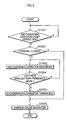
- Fig. 3 is a flow chart presenting the photographing control operation.
- the control unit 34 judges whether a user has inputted a photographing operation start instruction or not, by detecting an operation signal that is produced when the side key 14i is pressed halfway down (step S1001). If the photographing operation start instruction has been inputted (step S1001:Y), the control unit 34 further judges whether the folding mobile communications terminal 1 is in the closed state or not, by checking whether a detection signal has been outputted from the open/close state detecting unit 16 (step S1002).
- step S1003 When the folding mobile communications terminal 1 is not in the closed state (step S1002:N), the control unit 34 performs the photographing operation through the camera I/F 35 (step S1003). Then, the control unit 34 judges whether lightness is below a threshold level or not, by examining whether a voltage outputted thereto from the light sensor unit 37 is below a threshold voltage stored in the ROM 34a (step S1004).
- step S1004:Y When the lightness is below the threshold level (step S1004:Y), the control unit 34 has the camera I/F 35 terminate the photographing operation (step S1005). Then, the control unit 34 has the voice processing unit 39 generate a warning sound to notify that the photographing operation has been terminated (step S1006).
- step S1004:N When the lightness is not smaller than the threshold level (step S1004:N), the photographing operation is continued (step S1003 and step S1004).
- step S1002 When the folding mobile communications terminal 1 is in the closed state in step S1002 (step S1002:Y), the control unit 34 has the voice processing unit 39 generate a warning sound (step S1006).
- the folding mobile communications terminal according to the present invention is described in the above part with reference to the embodiment. However, the present invention is not limited to the above embodiment. Example modifications are given below.
- a folding mobile communications terminal and a photographing control method according to the present invention can be utilized to prevent attempts of taking sneak shots by means of a folding mobile communications terminal that has a photographing function.
Landscapes
- Engineering & Computer Science (AREA)
- Signal Processing (AREA)
- Computer Networks & Wireless Communication (AREA)
- Telephone Function (AREA)
- Studio Devices (AREA)
- Mobile Radio Communication Systems (AREA)
- Telephone Set Structure (AREA)
Abstract
Description
- The present invention relates to a folding built-in camera mobile communications terminal that has a photographing control function, and a photographing control method used in the terminal.
- In recent years, multiple functions have rapidly been developed for mobile communications terminals such as mobile telephones. Lately, built-in camera mobile telephones, which have a CCD (Charge Coupled Device) camera that employs semiconductor photodetectors for converting light into electrical signals, are coming into wide use.
- Built-in camera mobile telephones are convenient in terms of that a user can take them along anywhere and photograph desired objects anytime with ease. Here, "to photograph" represents a process of forming an image of an object on the surface of a semiconductor photodetector through a lens of a camera and converting the formed image into image data.
- A CCD camera is arranged on the rear side of such built-in camera mobile telephone. The object image photographed by the CCD camera is displayed on a liquid crystal screen provided on the front side of the mobile telephone. This enables the user to see the image of the photographed object on the liquid crystal screen on the spot. Furthermore, the user can store the photographed object image in the mobile telephone, or send it to his/her friends and family by email.
- Recently, however, such convenient built-in camera mobile telephones are often misused to take sneak shots, which poses a social problem. Also, built-in camera mobile telephones are made foldable so that they become compact. While this makes the built-in camera mobile telephones even more convenient, this causes apprehension about increase in the attempts of taking sneak shots using such increasingly convenient folding built-in camera mobile telephones.
- It is an object of the present invention to provide a folding built-in camera mobile communications terminal with a photographing control function to prevent attempts of taking sneak shots and a photographing control method used in the terminal.
- The above object is achieved by a folding mobile communications terminal that has a photographing function and is openable and closable. The folding mobile communications terminal includes (i) a detecting unit operable to detect whether the folding mobile communications terminal is in a closed state, and (ii) a photographing control unit operable to disable the photographing function when the detecting unit detects that the folding mobile communications terminal is in the closed state.
- The above object is also achieved by a folding mobile communications terminal that is openable and closable, which is characterized by including (i) a photographic lens that is positioned so as to be externally invisible when the mobile communications terminal is in a closed state, and (ii) a photographing unit operable to photograph an object through the photographic lens.
- The above object is also achieved by a photographing control method for a folding mobile communications terminal that has a photographing function and is openable and closable. The photographing control method includes (i) a detecting step of detecting whether the folding mobile communications terminal is in a closed state, and (ii) a photographing control step of disabling the photographing function when detected that the folding mobile communications terminal is in the closed state.
- The above-mentioned constituent features make a photographer unable to perform photographing when the folding mobile communications terminal is in the closed state and thereby in its compact state. It is therefore difficult for the photographer to take photos without being noticed by the people around him/her. As a result, the attempts of taking sneak shots are effectively prevented.
- The detecting unit may further detect an opening angle of the folding mobile communications terminal, and the photographing control unit may further disable the photographing function when the detected opening angle is below a threshold angle.
- These features can prevent the photographer from taking sneak shots using the folding mobile communications terminal in a partly-open state.
- The photographing control unit may include a warning unit operable to generate a warning when the detected opening angle is below the threshold angle.
- The photographing control unit may include a warning unit operable to generate a warning when the detecting unit detects that the folding mobile communications terminal is in the closed state.
- The above-mentioned constituent features enable the photographer to notice that the photographing function has been disabled.
- The folding mobile communications terminal further includes a lightness judging unit operable to (i) measure lightness which indicates a level of ambient light and (ii) judge whether the lightness is below a threshold level. The photographing control unit may further disable the photographing function when the lightness judging unit judges that the lightness is below the threshold level.
- These constituent features prohibit photographing performed in dark places, where sneak shots are likely to be taken. As a result, the above features can effectively prevent vile attempts, for example, taking downblouse and upskirt shots.
- The photographing control unit may include a warning unit operable to generate a warning when the lightness judging unit judges that the lightness is below the threshold level.
- This constituent feature can arouse attention of targets of sneak shots so that they easily notice the vile attempts.
- The folding mobile communications terminal may further include a lightness judging unit operable to (i) measure lightness which indicates a level of ambient light and (ii) judge whether the lightness is below a threshold level. The photographing control unit may include a warning unit operable to generate a warning when the lightness judging unit judges that the lightness is below the threshold level.
- The warning unit may generate the warning by emitting light.
- The warning unit may generate the warning by making the folding mobile communications terminal vibrate.
- The warning unit may generate the warning by outputting a voice message.
- The above-mentioned constituentfeaturesenable a warning to be generated when the photographer attempts to capture sneak shots in dark places. Accordingly, the targets of the sneak shots immediately notice that they are secretly photographed.
-
- Fig. 1 shows an external view of a folding mobile communications terminal 1 in the open state, wherein, more specifically, Fig. 1A shows a front view of the folding mobile communications terminal 1, Fig. 1B shows a right side view of the folding mobile communications terminal 1, and Fig. 1C shows a rear view of the folding mobile communications terminal 1.
- Fig. 2 is a functional block diagram showing a configuration of the folding mobile communications terminal 1.
- Fig. 3 is a flow chart showing, in detail, a photographing control operation performed by a control unit 34 (shown in Fig. 2).
- Fig. 4 is a flow chart showing, in detail, a photographing
control operation performed by the
control unit 34 when a warning sound is generated instead of terminating a photographing operation. -
- A folding mobile communications terminal to which an embodiment of the present invention relates is a folding mobile communications terminal that has a photographing function and is openable and closable. This folding mobile communications terminal detects whether the folds are closed, and disables the photographing function if the folds are closed.
- The following describes, in detail, the folding mobile communications terminal according to the present invention, with reference to the attached figures.
- Fig. 1 shows an external view of a folding mobile communications terminal 1 relating to the present embodiment in the open state, wherein, more specifically, Fig. 1A shows a front view of the folding mobile communications terminal 1, Fig. 1B shows a right side view of the folding mobile communications terminal 1, and Fig. 1C presents a rear view of the folding mobile communications terminal 1.
- The folding mobile communications terminal 1 includes: a
subhousing 11; asubhousing 12; amain display unit 13; anoperatingunit 36;amicrophone 15; anopen/close statedetectingunit 16; areceiver 17; anearphone terminal 18; anantenna 31; aspeaker 20; asub-display unit 21; acamera unit 22; ahinge unit 23; amirror 24; and anopening 25. - To make the description simple, the
subhousing 11, thesubhousing 12, the open/closestate detecting unit 16, aside key 14i included in theoperating unit 36, theearphone terminal 18, themirror 24, and theopening 25 are described first, and the other constituents will be described in the later part. - The
subhousing 11 and thesubhousing 12 are joined together by means of thehinge unit 23 provided therebetween, to form a foldable housing. Themain display unit 13 and thereceiver 17 are arranged on the inner surface (shown in Fig. 1A) of thesubhousing 11. Thespeaker 20 and thesub-display unit 21 are arranged on the outer surface (shown in Fig. 1C) of thesubhousing 11. - The operating
unit 36 and themicrophone 15 are arranged on the inner surface (shown in Fig. 1A) of thesubhousing 12. Thecamera unit 22, themirror 24, and theopening 25 are arranged on the outer surface (shown in Fig. 1C) of thesubhousing 12. The side key 14i that functions as a shutter button for performing photographing with thecamera unit 22 is arranged on the side of thesubhousing 12. - Also, a photographic lens included in the
camera unit 22 is arranged on the surface of thesubhousing 12. - The side key 14i is used to perform photographing with the
camera unit 22. The side key 14i has two states, namely, halfway pressed and fully pressed. When the side key 14i is halfway pressed, a photographing operation start instruction is issued to a control unit 34 (described later). When fully pressed, a photographing execution instruction is issued. - Here, the "photographing operation start instruction" is an instruction to have the
camera unit 22 start capturing an object image and sequentially display, on themain display unit 13, as image data, the captured object image. - The "photographing execution instruction" is an instruction to have a memory unit 38 (described later) store an object image that is photographed by the
camera unit 22 at the point of the issuance of the photographing execution instruction. - The open/close
state detecting unit 16 is a microswitch that mechanically detects whether the folding mobile communications terminal 1 is in the open state or the closed state. For instance, the detection is performed in the following manner. A convex part (indicated byreference numeral 16a in Fig. 1A) is provided on thesubhousing 11. If the convex part is pressing down the open/closestate detecting unit 16, the open/closestate detecting unit 16 mechanically detects that the folding mobile communications terminal 1 is in the closed state, and outputs a detection signal to the control unit 34 (described later). In this way, thecontrol unit 34 can detect that the folding mobile communications terminal 1 is in the closed state. - As an alternative, the open/close
state detecting unit 16 may perform the detection in the following manner. A light sensor is provided in the open/closestate detecting unit 16. This light sensor generates a voltage according to the quantity of light received by the light sensor through an opening provided on the open/closestate detecting unit 16. The folding mobile communications terminal 1 is judged as being in the open state if the generated voltage is greater than a threshold voltage that is determined beforehand in connection with the open state, or judged as being in the partly-open state if the generated voltage is no more than the threshold voltage. Likewise, the folding mobile communications terminal 1 is judged as being in the closed state if the generated voltage is below a threshold voltage that is determined beforehand in connection with the closed state. - Here, the "partly-open state" represents a state in which the folding mobile communications terminal 1 is not completely open, for example, the opening angle between the inner surfaces of the
subhousing 11 andsubhousing 12 is not more than a predetermined angle, say, 90 degrees. - The detection may be performed using other known techniques, such as using an encoder to detect the opening angle between the subhousing 11 and the
subhousing 12. - The
earphone terminal 18 is used for connecting an earphone microphone to the folding mobile communications terminal 1. - The
mirror 24 is used when a user attempts to take a photo of himself/herself. More specifically, the user can make sure that the photographic lens of thecamera unit 22 properly finds himself/herself, by checking whether s/he can see his/her own reflections in themirror 24. - The
opening 25 lets ambient light in so that a light sensor unit 37 (described later) can detect a level of the ambient light of the subhousing 12(hereinafter referred to as lightness). - Fig. 2 is a functional block diagram presenting a configuration of the folding mobile communications terminal 1. As shown, the folding mobile communications terminal 1 includes: the
antenna 31; a transmitting/receivingunit 32; a modulating/demodulating unit 33; thecontrol unit 34; themain display unit 13; thesub-display unit 21; thecamera unit 22; a camera interface (I/F) 35; the operatingunit 36; avoice processing unit 39; themicrophone 15; thereceiver 17; thelight sensor unit 37; and thememory unit 38. - The
antenna 31 transmits and receives radio waves for communication. - The transmitting/receiving
unit 32 transmits and receives data which is communicated via radio waves. Here, the communication data includes: sound data of a telephone conversation; character information; image data; control data used to control communication (e.g. information regarding incoming voice communication such as a telephone number of a caller, information regarding incoming emails and text messages that are sent using the Short Message Service (SMS) bearer) and the like. - The modulating/
demodulating unit 33 modulates communication data to be transmitted. The modulating/demodulating unit 33 also demodulates received communication data, and outputs it to thevoice processing unit 39. - The
control unit 34 includes, for example, a microprocessor, a Read Only Memory (ROM) 34a, andaRandomAccess Memory (RAM) 34b. Thecontrol unit 34 performs various kinds of control such as photographing control, according to a control program stored in theROM 34a. More specifically, thecontrol unit 34 performs the photographing control based on: the user's instruction concerning photographing (a photographing operation start instruction or a photographing execution instruction) inputted via the side key 14i; a detection signal outputted from the open/closestate detecting unit 16; and a voltage which is outputted from thelight sensor unit 37. When thecontrol unit 34 receives the photographing execution instruction, thecontrol unit 34 reads, from theRAM 34b, image data of a captured object image and stores the image data in thememory unit 38. - The above-mentioned photographing control performed by the
control unit 34 is explained in detail later. - The
ROM 34a stores the control program mentioned above and a threshold voltage which is compared with the voltage outputted from thelight sensor unit 37. - The
RAM 34b stores communication data received and to be transmitted; image data of a captured obj ect image, phonebook data (for example, 999 memory dial entries) and the like, temporarily or until the user erases or changes the data via the operatingunit 36. - Note that a large-capacity RAM dedicated to store image data of a captured object image may be provided in addition to the
RAM 34b. - The
main display unit 13 can be realized by any of a color liquid crystal display apparatus, a digital micromirror device (DMD), an organic electro luminescence (EL) display apparatus, a plasma display panel (PDP) and the like. Themain display unit 13 displays: an object image captured by the camera unit 22 (a moving image or an intermittent image in almost real time captured after a photographing operation start instruction is issued but before a photographing execution instruction is issued, or a still image photographed at the point of the issuance of the photographing execution instruction); information that has to be notified to the user such as a call register; character information including emails, phonebook data and the like; current time information and the like. Here, when the open/closestate detecting unit 16 outputs a detection signal indicating that the folding mobile communications terminal 1 is in the closed state and thecontrol unit 34 detects the detection signal, the display on themain display unit 13 i s turned of f or a backlight (not illustrated) installed in themain display unit 13 is switched off by thecontrol unit 34. - The
sub-display unit 21 can be realized by any of color liquid crystal display apparatus, a DMD, an organic EL display apparatus, a PDP and the like. Thesub-display unit 21 displays: a standby screen; information that has to be notified to the user such as a call register; current time information and the like. - The
camera unit 22 is connected to thecontrol unit 34 via a flexible cable and the camera I/F 35, and includes a built-in camera. An image of an object is formed on the surface of semiconductor photodetectors through a photographic lens of the built-in camera (the photographic lens is positioned at thecamera unit 22 on the outer surface of thesubhousing 12 shown in Fig. 1C). The formed image is converted into electrical signals of a certain quantity that is determined in accordance with the amount of light received by each of the photodetectors. The electrical signals are then analog-to-digital converted, and stored into theRAM 34b in thecontrol unit 34 via the camera I/F 35 as image data. A CCD camera, a CMOS (complementary metal oxide semiconductor) camera or the like can be used for the built-in camera. - The camera I/
F 35 has thecamera unit 22 start a photographing operation responding to a photographing operation start instruction from thecontrol unit 34. The camera I/F 35 has thecamera unit 22 terminate the photographing operation responding to a photographing operation terminating instruction from thecontrol unit 34. - The "photographing operation" is an operation in which image data of an object image captured by means of the
camera unit 22 is sequentially outputted, from thecamera unit 22, to thecontrol unit 34 and stored in theRAM 34b. - The operating
unit 36 includes various function keys to receive the user's instructions. According to the example of Fig. 1A, the operatingunit 36 includes:multi-function keys 14a; a navigation key 14b; anemail key 14c; an OK key 14d; an end key 14e; akeypad 14f; an Internet key 14g; a start key 14h; and the side key 14i. - It should be noted that Fig. 1A shows only one example of various function key types and arrangements included in the operating
unit 36, and the present invention is not limited to such. - The
multi-function keys 14a have several different functions according to the contents of display on themain display unit 13. In detail, when a menu screen is displayed, themulti-function keys 14a function as selection keys for the user to choose a desired item. When a standby screen is displayed, themulti-function keys 14a function as keys for accessing the menu screen. - The navigation key 14b is used to move a cursor up/down/left/right. Depending on the contents of display on the
main display unit 13, the navigation key 14b may function as a key to set a sound volume, a key to access stored telephone numbers, or a key to perform kana-to-kanji conversion. - The
email key 14c is used to display an email on themain display unit 13. Theemail key 14c is also used for deleting characters displayed on themain display unit 13 or for returning to an immediately preceding display. - The OK key 14d is used to confirm the selection made using the
multi-function keys 14a. - The end key 14e is used for switching the folding mobile communications terminal 1 on/off, and ending calls.
- The
keypad 14f is used to input numbers and characters. - The Internet key 14g is used for accessing a screen for Internet connection.
- The start key 14h is used to start incoming and outgoing phone calls.
- The above-mentioned various function keys can be push buttons, a touch panel, or jog dials.
- The
voice processing unit 39 digital-to-analog converts communication data which is outputted from the modulating/demodulating unit 33, and outputs the communication data to thereceiver 17 in the form of sound signals. Thevoice processing unit 39 also converts sounds that are outputted from themicrophone 15 into sound signals, and outputs the sound signals to the modulating/demodulating unit 33 as communication data to be transmitted. - Also, the
voice processing unit 39 has thespeaker 20 generate a warning sound, in response to a warning sound generating instruction issued by thecontrol unit 34. - The
microphone 15 outputs sounds inputted thereto to thevoice processing unit 39. - The
receiver 17 reproduces sounds based on the sound signals that are outputted from thevoice processing unit 39. - The
light sensor unit 37 is realized by a detecting circuit including a light sensor (a photodiode, for example) that is a device for converting light signals into electrical signals, a resistor, and a transistor. Thelight sensor unit 37 outputs, to thecontrol unit 34, a voltage generated in accordance with the quantity of light received by the light sensor through theopening 25. Theopening 25 is arranged so as to be close to the photographic lens of thecamera unit 22 as shown in Fig. 1C. - Note that the position of the
opening 25 is not limited to the position shown in Fig. 1C. It can be arranged somewhere on the surface of one of thesubhousing 11 and thesubhousing 12. - The
memory unit 38 receives image data of a captured object image from thecontrol unit 34, and stores it. - The following part describes in detail the photographing control operation performed by the
control unit 34 with reference to Fig. 3, which is a flow chart presenting the photographing control operation. - The
control unit 34 judges whether a user has inputted a photographing operation start instruction or not, by detecting an operation signal that is produced when the side key 14i is pressed halfway down (step S1001). If the photographing operation start instruction has been inputted (step S1001:Y), thecontrol unit 34 further judges whether the folding mobile communications terminal 1 is in the closed state or not, by checking whether a detection signal has been outputted from the open/close state detecting unit 16 (step S1002). - When the folding mobile communications terminal 1 is not in the closed state (step S1002:N), the
control unit 34 performs the photographing operation through the camera I/F 35 (step S1003). Then, thecontrol unit 34 judges whether lightness is below a threshold level or not, by examining whether a voltage outputted thereto from thelight sensor unit 37 is below a threshold voltage stored in theROM 34a (step S1004). - When the lightness is below the threshold level (step S1004:Y), the
control unit 34 has the camera I/F 35 terminate the photographing operation (step S1005). Then, thecontrol unit 34 has thevoice processing unit 39 generate a warning sound to notify that the photographing operation has been terminated (step S1006). - When the lightness is not smaller than the threshold level (step S1004:N), the photographing operation is continued (step S1003 and step S1004).
- When the folding mobile communications terminal 1 is in the closed state in step S1002 (step S1002:Y), the
control unit 34 has thevoice processing unit 39 generate a warning sound (step S1006). - The folding mobile communications terminal according to the present invention is described in the above part with reference to the embodiment. However, the present invention is not limited to the above embodiment. Example modifications are given below.
- (1) According to the above embodiment, the
camera unit 22 is arranged on the outer surface of thesubhousing 12. However, thecamera unit 22 may be arranged on the inner surface of one of thesubhousing 11 and thesubhousing 12. In this case, if the display screen of thesub-display unit 21 is large enough to display image data, image data outputted from thecamera unit 22 can be displayed on thesub-display unit 21. This feature allows a photographer to perform photographing only when the folding mobile communications terminal 1 is in the open state. This means that, even without the open/closestate detecting unit 16, it is possible to prevent attempts of taking sneak shots using the folding mobile communications terminal 1 in the closed state. - (2) In the photographing control operation according to
the above embodiment, the photographing operation is terminated
when the lightness is below the threshold level, as shown in
the flow chart of Fig. 3 (step S1004 and step S1005). Instead
of terminating the photographing operation, however, a warning
sound may be generated and the photographing operation may be
continued. This alternative photographing control operation
is shown in the flow chart of Fig. 4. As shown in Fig. 4, when
the lightness is below the threshold level (step S1004:Y), the
control unit 34 has thevoice processing unit 39 generate a warning sound (step S1006). As steps of the flow chart of Fig. 4 are the same as those of the flow chart of Fig. 3, their explanation will be omitted. - (3) In the photographing control operation according to the above embodiment and the modification (2), a warning sound is generated in step S1006 as shown in Fig. 3 and Fig. 4. Note that, however, the warning sound can be replaced with any of a warning voice message, warning light, and vibration alert.
- (4) In the photographing control operation according to
the above embodiment, when the folding mobile communications
terminal 1 is in the closed state, the photographing operation
is terminated, as shown in Fig. 3. However, the photographing
operation may be also terminated, when the folding mobile
communications terminal 1 is in the partly-open state. Whether
the folding mobile communications terminal 1 is in the
partly-open state or not is, for example, detected in the
following manner. A light sensor is provided in the open/close
state detecting unit 16. This light sensor outputs, to thecontrol unit 34, a voltage generated according to the quantity of light received by the light sensor. Thecontrol unit 34 compares the voltage with a threshold voltage that is determined beforehand in connection with the partly-open state, to perform the detection. In other words, thecontrol unit 34 examines whether the voltage outputted from the light sensor is below the above threshold voltage or not, so as to judge whether the folding mobile communications terminal 1 is in one of the closed and partly-open states, or not in step S1002 of the flow chart in Fig. 3. - (5) As for the photographing control operation according
to the above embodiment, if the
control unit 34 judges that the folding mobile communications terminal 1 is in the closed state while the photographing operation is performed, thecontrol unit 34 may terminate the photographing operation, generate a warning sound, or terminate the photographing operation as well as generate a warning sound. - (6) According to the above embodiment, a photographing control function for a folding mobile communications terminal is realized. However, the present invention is equally applicable to other devices such as digital cameras and video cameras, as long as they are foldable.
-
- A folding mobile communications terminal and a photographing control method according to the present invention can be utilized to prevent attempts of taking sneak shots by means of a folding mobile communications terminal that has a photographing function.
Claims (12)
- A folding mobile communications terminal that has a photographing function and is openable and closable, comprising:a detecting unit operable to detect whether the mobile communications terminal is in a closed state; anda photographing control unit operable to disable the photographing function when the detecting unit detects that the mobile communications terminal is in the closed state.
- The mobile communications terminal of Claim 1, wherein
the detecting unit detects an opening angle of the mobile communications terminal, and
the photographing control unit disables the photographing function when the detected opening angle is below a threshold angle. - The mobile communications terminal of Claim 2, wherein
the photographing control unit includes
a warning unit operable to generate a warning when the detected opening angle is below the threshold angle. - The mobile communications terminal of Claim 1, wherein
the photographing control unit includes
a warning unit operable to generate a warning when the detecting unit detects that the mobile communications terminal is in the closed state. - The mobile communications terminal of Claim 1, further comprising
a lightness judging unit operable to (i) measure lightness which indicates a level of ambient light, and (ii) judge whether the lightness is below a threshold level, wherein
when the lightness judging unit judges that the lightness is below the threshold level, the photographing control unit disables the photographing function. - The mobile communications terminal of Claim 5, wherein
the photographing control unit includes
a warning unit operable to generate a warning when the lightness judging unit judges that the lightness is below the threshold level. - The mobile communications terminal of Claim 1, further comprising
a lightness udging unit operable to (i) measure lightness which indicates a level of ambient light, and (ii) judge whether the lightness is below a threshold level, wherein
the photographing control unit includes
a warning unit operable to generate a warning when the lightness judging unit judges that the lightness is below the threshold level. - The mobile communications terminal of Claim 7, wherein
the warning unit generates the warning by emitting light. - The mobile communications terminal of Claim 7, wherein
the warning unit generates the warning by making the mobile communications terminal vibrate. - The mobile communications terminal of Claim 7, wherein
the warning unit generates the warning by outputting a voice message. - A folding mobile communications terminal that is openable and closable, comprising:a photographic lens which is positioned so as to be externally invisible when the mobile communications terminal is in a closed state; anda photographing unit operable to photograph an object through the photographic lens.
- A photographing control method for a folding mobile communications terminal that has a photographing function and is openable and closable, comprising:a detecting step of detecting whether the mobile communications terminal is in a closed state; anda photographing control step of disabling the photographing function when detected that the mobile communications terminal is in the closed state.
Applications Claiming Priority (3)
| Application Number | Priority Date | Filing Date | Title |
|---|---|---|---|
| JP2001105199 | 2001-04-03 | ||
| JP2001105199A JP3392831B2 (en) | 2001-04-03 | 2001-04-03 | Foldable communication terminal device and imaging control method |
| PCT/JP2002/003245 WO2002082786A1 (en) | 2001-04-03 | 2002-04-01 | Collapsible cellular communication terminal having a camera having photographing control function and photographing control method in the terminal |
Publications (2)
| Publication Number | Publication Date |
|---|---|
| EP1385318A1 true EP1385318A1 (en) | 2004-01-28 |
| EP1385318A4 EP1385318A4 (en) | 2005-09-07 |
Family
ID=18957924
Family Applications (1)
| Application Number | Title | Priority Date | Filing Date |
|---|---|---|---|
| EP02707274A Withdrawn EP1385318A4 (en) | 2001-04-03 | 2002-04-01 | EXTENSIBLE CELLULAR COMMUNICATION TERMINAL HAVING CAMERA WITH PHOTOGRAPHIC CONTROL FUNCTION AND PHOTOGRAPHIC CONTROL METHOD IN THE TERMINAL |
Country Status (7)
| Country | Link |
|---|---|
| US (1) | US7345696B2 (en) |
| EP (1) | EP1385318A4 (en) |
| JP (1) | JP3392831B2 (en) |
| KR (1) | KR100792100B1 (en) |
| CN (1) | CN100508527C (en) |
| CA (1) | CA2442132C (en) |
| WO (1) | WO2002082786A1 (en) |
Cited By (5)
| Publication number | Priority date | Publication date | Assignee | Title |
|---|---|---|---|---|
| EP1551192A1 (en) * | 2003-12-30 | 2005-07-06 | Lg Electronics Inc. | Method for transmitting a message of a mobile terminal |
| WO2006023058A1 (en) * | 2004-08-11 | 2006-03-02 | Motorola Inc. | Passivation of external keys of a communication device in a closed position |
| EP2479977A3 (en) * | 2002-10-24 | 2012-10-03 | Panasonic Corporation | Digital camera and portable telephone equiped with digital camera |
| EP1612526A4 (en) * | 2003-03-26 | 2012-11-21 | Semiconductor Energy Lab | OPTICAL SENSOR FOR DETECTING LIGHT BEAMS FROM MULTIPLE DIRECTIONS, MOBILE COMMUNICATION DEVICE, AND DISPLAY METHOD |
| EP2738601A4 (en) * | 2012-09-19 | 2014-08-13 | Huawei Device Co Ltd | VIEWING PROCESSING METHOD AND TERMINAL DEVICE |
Families Citing this family (30)
| Publication number | Priority date | Publication date | Assignee | Title |
|---|---|---|---|---|
| US7192235B2 (en) | 2001-11-01 | 2007-03-20 | Palm, Inc. | Temporary messaging address system and method |
| JP4080395B2 (en) * | 2002-08-02 | 2008-04-23 | シャープ株式会社 | Portable information processing device |
| JP3675430B2 (en) * | 2002-09-20 | 2005-07-27 | 株式会社日立製作所 | Mobile phone |
| KR100455776B1 (en) * | 2002-11-18 | 2004-11-06 | 엘지전자 주식회사 | A mobile telecommunication terminal having a camera |
| US20040185922A1 (en) * | 2003-02-06 | 2004-09-23 | Thomas Sutton | Smartphone with novel opening mechanism |
| JP2004246605A (en) * | 2003-02-13 | 2004-09-02 | Sony Corp | Information processing equipment |
| JP2004246603A (en) * | 2003-02-13 | 2004-09-02 | Sony Corp | Information processing equipment |
| WO2004075428A2 (en) * | 2003-02-19 | 2004-09-02 | Flextronics Sales & Marketing (A-P) Ltd. | Personal entertainment device (ped) with double-opening flap |
| US7231229B1 (en) | 2003-03-16 | 2007-06-12 | Palm, Inc. | Communication device interface |
| US7835504B1 (en) | 2003-03-16 | 2010-11-16 | Palm, Inc. | Telephone number parsing and linking |
| USD519502S1 (en) | 2003-03-17 | 2006-04-25 | Palm, Inc. | Handheld device |
| AU2003232964A1 (en) * | 2003-04-17 | 2004-11-04 | Nokia Corporation | An improved mobile camera telephone |
| KR100548370B1 (en) * | 2003-07-04 | 2006-02-02 | 엘지전자 주식회사 | Video transmission selection device of video call mobile terminal |
| US7742285B2 (en) | 2003-11-26 | 2010-06-22 | Sharp Kabushiki Kaisha | Folding portable terminal |
| US7495700B2 (en) * | 2004-04-05 | 2009-02-24 | Casio Computer Co., Ltd. | Moving image capture device, moving image capture control method, and moving image capture control program |
| WO2005114965A1 (en) * | 2004-05-13 | 2005-12-01 | Flextronics International Usa, Inc. | Smartphone with novel opening mechanism |
| JP4587166B2 (en) * | 2004-09-14 | 2010-11-24 | キヤノン株式会社 | Moving body tracking system, photographing apparatus, and photographing method |
| US7268799B2 (en) * | 2004-12-03 | 2007-09-11 | Motorola, Inc. | Multi-function device illumination control system and method |
| US20060217148A1 (en) * | 2005-03-23 | 2006-09-28 | Eastman Kodak Company | Camera phone with large sensor |
| KR100703332B1 (en) * | 2005-06-07 | 2007-04-03 | 삼성전자주식회사 | How to change the operation mode of a mobile terminal |
| US7917180B2 (en) * | 2006-06-20 | 2011-03-29 | Samsung Electronics Co., Ltd. | Button with an included display |
| US20080133599A1 (en) * | 2006-12-05 | 2008-06-05 | Palm, Inc. | System and method for providing address-related location-based data |
| US20080134088A1 (en) * | 2006-12-05 | 2008-06-05 | Palm, Inc. | Device for saving results of location based searches |
| CN101601259A (en) * | 2007-01-12 | 2009-12-09 | 松下电器产业株式会社 | Method for controlling voice recognition function of portable terminal and wireless communication system |
| US9140552B2 (en) | 2008-07-02 | 2015-09-22 | Qualcomm Incorporated | User defined names for displaying monitored location |
| US20080254811A1 (en) | 2007-04-11 | 2008-10-16 | Palm, Inc. | System and method for monitoring locations of mobile devices |
| US9031583B2 (en) | 2007-04-11 | 2015-05-12 | Qualcomm Incorporated | Notification on mobile device based on location of other mobile device |
| US8509757B2 (en) * | 2010-05-18 | 2013-08-13 | John Schlueter | Cell phone with automatic dialing lockout |
| CN103139355A (en) * | 2011-11-22 | 2013-06-05 | 索尼爱立信移动通讯有限公司 | Foldable electronic device and detection method of opening and closing modes thereof |
| CN110417939B (en) * | 2018-04-26 | 2021-03-30 | Oppo广东移动通信有限公司 | Electronic device |
Family Cites Families (13)
| Publication number | Priority date | Publication date | Assignee | Title |
|---|---|---|---|---|
| JP3842876B2 (en) * | 1996-09-27 | 2006-11-08 | 株式会社リコー | Digital camera |
| JPH10234080A (en) | 1997-02-19 | 1998-09-02 | Nippon Soken Inc | Mobile communication device |
| JP4199837B2 (en) | 1997-05-29 | 2008-12-24 | カシオ計算機株式会社 | Compound equipment |
| JP3098488B2 (en) * | 1998-04-20 | 2000-10-16 | 埼玉日本電気株式会社 | Missed call notification device and method for foldable mobile phone |
| GB2372664B (en) | 1998-05-08 | 2002-11-27 | Orange Personal Comm Serv Ltd | Mobile communications |
| US6687515B1 (en) * | 1998-10-07 | 2004-02-03 | Denso Corporation | Wireless video telephone with ambient light sensor |
| JP2000217023A (en) | 1999-01-25 | 2000-08-04 | Canon Inc | Electronic camera with electronic display |
| JP3288347B2 (en) * | 1999-08-09 | 2002-06-04 | 埼玉日本電気株式会社 | External pressure breakage warning system and method for foldable mobile phone device |
| JP2001069395A (en) | 1999-08-27 | 2001-03-16 | Hitachi Ltd | Video camera |
| KR20010068807A (en) * | 2000-01-10 | 2001-07-23 | 윤종용 | Radiotelephone for visual communication |
| JP2001197457A (en) | 2000-01-12 | 2001-07-19 | Mitsubishi Electric Corp | mobile phone |
| JP2002290818A (en) | 2001-03-28 | 2002-10-04 | Denso Corp | Mobile terminal |
| KR20040100152A (en) * | 2003-05-21 | 2004-12-02 | 엘지전자 주식회사 | Photography limitation method of mobile phone |
-
2001
- 2001-04-03 JP JP2001105199A patent/JP3392831B2/en not_active Expired - Fee Related
-
2002
- 2002-04-01 KR KR1020037012911A patent/KR100792100B1/en not_active Expired - Fee Related
- 2002-04-01 EP EP02707274A patent/EP1385318A4/en not_active Withdrawn
- 2002-04-01 US US10/474,015 patent/US7345696B2/en not_active Expired - Fee Related
- 2002-04-01 CA CA2442132A patent/CA2442132C/en not_active Expired - Fee Related
- 2002-04-01 WO PCT/JP2002/003245 patent/WO2002082786A1/en not_active Ceased
- 2002-04-01 CN CNB028107926A patent/CN100508527C/en not_active Expired - Fee Related
Non-Patent Citations (2)
| Title |
|---|
| No further relevant documents disclosed * |
| See also references of WO02082786A1 * |
Cited By (8)
| Publication number | Priority date | Publication date | Assignee | Title |
|---|---|---|---|---|
| EP2479977A3 (en) * | 2002-10-24 | 2012-10-03 | Panasonic Corporation | Digital camera and portable telephone equiped with digital camera |
| EP1612526A4 (en) * | 2003-03-26 | 2012-11-21 | Semiconductor Energy Lab | OPTICAL SENSOR FOR DETECTING LIGHT BEAMS FROM MULTIPLE DIRECTIONS, MOBILE COMMUNICATION DEVICE, AND DISPLAY METHOD |
| US9772221B2 (en) | 2003-03-26 | 2017-09-26 | Semiconductor Energy Laboratory Co., Ltd. | Multidirectional photodetector, a portable communication tool having thereof and a method of displaying |
| EP1551192A1 (en) * | 2003-12-30 | 2005-07-06 | Lg Electronics Inc. | Method for transmitting a message of a mobile terminal |
| EP1791379A1 (en) * | 2003-12-30 | 2007-05-30 | LG Electronics Inc. | Method for transmitting a message of a mobile terminal |
| WO2006023058A1 (en) * | 2004-08-11 | 2006-03-02 | Motorola Inc. | Passivation of external keys of a communication device in a closed position |
| EP2738601A4 (en) * | 2012-09-19 | 2014-08-13 | Huawei Device Co Ltd | VIEWING PROCESSING METHOD AND TERMINAL DEVICE |
| US9204027B2 (en) | 2012-09-19 | 2015-12-01 | Huawei Device Co., Ltd. | Method for photographing processing and terminal device |
Also Published As
| Publication number | Publication date |
|---|---|
| JP2002305565A (en) | 2002-10-18 |
| JP3392831B2 (en) | 2003-03-31 |
| US20040166829A1 (en) | 2004-08-26 |
| CN100508527C (en) | 2009-07-01 |
| EP1385318A4 (en) | 2005-09-07 |
| CA2442132C (en) | 2011-01-25 |
| KR100792100B1 (en) | 2008-01-04 |
| WO2002082786A1 (en) | 2002-10-17 |
| CA2442132A1 (en) | 2002-10-17 |
| US7345696B2 (en) | 2008-03-18 |
| CN1518828A (en) | 2004-08-04 |
| KR20040011493A (en) | 2004-02-05 |
Similar Documents
| Publication | Publication Date | Title |
|---|---|---|
| CA2442132C (en) | Folding built-in camera mobile communications terminal that has photographing control function and photographing control method used in the terminal | |
| KR100478108B1 (en) | Fold type communication terminal device and the display control method | |
| JP2003244301A (en) | Portable information terminal | |
| CN100505035C (en) | Communication terminal device and character display method for communication terminal device | |
| JP2004032442A (en) | Mobile terminal and its notification method | |
| JP3726073B2 (en) | Mobile terminal device | |
| JP3778807B2 (en) | Foldable communication terminal device and image display method | |
| JP2005323241A (en) | Mobile phone | |
| JP4313545B2 (en) | Folding mobile phone device with camera | |
| JP2005191899A (en) | Mobile communication device with camera | |
| US20050070334A1 (en) | Cellular phone | |
| CN100512333C (en) | Portable communication terminal with image shooting function | |
| JP2004260433A (en) | Mobile phone with video camera | |
| JP2007005915A (en) | Mobile terminal device | |
| JP4241337B2 (en) | Mobile phone and display control program | |
| KR20050042852A (en) | Mobile communication terminal display method using touch screen | |
| JP3574084B2 (en) | Foldable communication terminal device and imaging control method | |
| KR100557184B1 (en) | Method for displaying an image in a portable terminal having a camera and two display units | |
| JP4493375B2 (en) | Mobile terminal device | |
| JP4527790B2 (en) | Mobile terminal device | |
| KR100606045B1 (en) | Camera mode switching method of mobile communication terminal with camera module | |
| JP2004320622A (en) | Electronic apparatus with camera, program and recording medium | |
| JP2006108982A (en) | Image pickup device | |
| JP2008104220A (en) | Mobile terminal and notification method thereof | |
| KR20050067283A (en) | Mobile communication terminal having built in camera module and a method for changing camera mode using the same |
Legal Events
| Date | Code | Title | Description |
|---|---|---|---|
| PUAI | Public reference made under article 153(3) epc to a published international application that has entered the european phase |
Free format text: ORIGINAL CODE: 0009012 |
|
| 17P | Request for examination filed |
Effective date: 20031028 |
|
| AK | Designated contracting states |
Kind code of ref document: A1 Designated state(s): AT BE CH CY DE DK ES FI FR GB GR IE IT LI LU MC NL PT SE TR |
|
| AX | Request for extension of the european patent |
Extension state: AL LT LV MK RO SI |
|
| A4 | Supplementary search report drawn up and despatched |
Effective date: 20050725 |
|
| 17Q | First examination report despatched |
Effective date: 20071109 |
|
| RAP1 | Party data changed (applicant data changed or rights of an application transferred) |
Owner name: KYOCERA CORPORATION |
|
| STAA | Information on the status of an ep patent application or granted ep patent |
Free format text: STATUS: THE APPLICATION IS DEEMED TO BE WITHDRAWN |
|
| 18D | Application deemed to be withdrawn |
Effective date: 20121101 |