EP1385309A2 - Power control for multicarrier transmission - Google Patents
Power control for multicarrier transmission Download PDFInfo
- Publication number
- EP1385309A2 EP1385309A2 EP03102042A EP03102042A EP1385309A2 EP 1385309 A2 EP1385309 A2 EP 1385309A2 EP 03102042 A EP03102042 A EP 03102042A EP 03102042 A EP03102042 A EP 03102042A EP 1385309 A2 EP1385309 A2 EP 1385309A2
- Authority
- EP
- European Patent Office
- Prior art keywords
- power
- cutback
- psd
- pcb
- level
- Prior art date
- Legal status (The legal status is an assumption and is not a legal conclusion. Google has not performed a legal analysis and makes no representation as to the accuracy of the status listed.)
- Granted
Links
Images


Classifications
-
- H—ELECTRICITY
- H04—ELECTRIC COMMUNICATION TECHNIQUE
- H04L—TRANSMISSION OF DIGITAL INFORMATION, e.g. TELEGRAPHIC COMMUNICATION
- H04L27/00—Modulated-carrier systems
- H04L27/26—Systems using multi-frequency codes
- H04L27/2601—Multicarrier modulation systems
- H04L27/2614—Peak power aspects
Definitions
- the invention relates to digital communications, and, more particularly, to discrete multitone communication systems and corresponding circuitry and methods.
- Digital subscriber line (DSL) technologies provide potentially large bandwidth (e.g., greater than 20 MHz for subscribers close to the central office) for digital communication over existing telephone subscriber lines (the copper plant).
- the subscriber lines can provide this bandwidth despite their original design for voice band (0-4 kHz) analog communication.
- ADSL asymmetric DSL
- DMT discrete multitone
- the bits of a codeword are allocated among the subchannels for modulation to form an ADSL symbol for transmission.
- Figure 2a illustrates the use of the Fast Fourier transform in a system having, for example, 256 tones with each tone treated as a QAM subchannel (except dc tone 0) and so the kth tone encoding corresponds with a complex number X(k) for 0 ⁇ k ⁇ 255.
- Extending to 512 tones by conjugate symmetry allows the 512-point IFFT to yield real samples x(n), 0 ⁇ n ⁇ 511, of the transformed block (symbol); and a DAC converts these samples into a segment of the transmitted waveform x(t).
- Figure 2a also notes a cyclic prefix for each symbol which allows for simplified equalization for the interference of successive symbols which arises from the non-ideal impulse response of the transmission channel.
- Annex A of the ADSL standard G.992.3 has subchannels separated by 4.3125 KHz and a band extending up to 1104 KHz for 256 subchannels.
- Annex A also provides power spectral density (PSD) masks for both central office and customer transmitters plus 0-40 dB power cutback levels to be applied according to dynamic range measured by the central office and customer receivers during initialization procedures.
- PSD power spectral density
- the PSD can be shaped for efficient operation, such as limiting crosstalk among physically adjacent subscriber lines and reducing the transmit power requirements.
- power cutbacks for transmitters with shaped power spectral densities (PSDs) can render the low power portions of the spectrum useless.
- the present invention provides a ceiling-based power cutback method for discrete multitone systems.
- a method of transmit power adjustment in a multitone communication system comprising: for a power spectral density P(i) expressed in terms of dBm/Hz where i indexes subchannels of multitone system, for each subchannel k, changing P(k) to the minimum of P(k) and P max - PCB where P max is the maximum of the P(i) and PCB is a power cutback level in terms of dB.
- said PCB is selected from the range 0dB to 40 dB.
- said multitone system is an asymmetrical digital subscriber line system, and said PCB is selected as the larger of a power cutback selected by a central office transceiver and a power cutback selected by a customer transceiver.
- Preferred embodiments provide power cutback methods useful for multitone systems employing transmit power optimization and with shaped power spectral density (PSD) masks.
- the methods apply a power ceiling (saturation) instead of a uniform power decrease across an entire PSD mask passband. This effectively boosts the relative power of the low power portions of a shaped PSD while still achieving essentially the same total power reduction as a uniform power cutback.
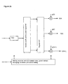
- Figures 2a-2b illustrate functional blocks of a discrete multitone system which may use the preferred embodiment methods with PSD and framing part of the encoding prior to IFFT in the transmitter, whereas dynamic range measurements of the received signal occur in the receiver.
- Preferred embodiment communications systems use preferred embodiment methods.
- customer premises transceivers (modems) and central office transceivers (modems) could each include one or more digital signal processors (DSPs) and/or other programmable devices with stored programs for performance of the signal processing of the preferred embodiment methods.
- DSPs digital signal processors
- the transceivers may also contain analog integrated circuits for amplification of inputs and/or outputs and conversion between analog and digital; and these analog and processor circuits may be integrated as a system on a chip (SoC).
- SoC system on a chip
- the stored programs may, for example, be in ROM or flash EEPROM integrated with the processor or external.
- Exemplary DSP cores could be in the TMS320C6xxx or TMS320C5xxx families from Texas Instruments.
- Power cutback preferred embodiment methods are ceiling-based and allow for good performance in the high frequency subchannels while achieving the maximum amount of power reduction. Power cutback generally prevents saturation at the receiver for short loops and limits unnecessary interference (crosstalk) to neighboring loops.
- the central office and customer transceivers make measurements of received signal amplitude and/or power which are used to set the automatic gain controls and to signal a power cutback level to the other transmitter.
- the G.992.3 standard provides for power cutback levels from 0 to 40 dB in 1 dB increments to be applied to the passband; the 6-bit variable PCB encodes the power cutback level. Because systems operating in frequencies above 1104 kHz typically use a shaped PSD, the preferred embodiment power cutback methods should take the shaping into account.
- the preferred embodiment power cutback methods apply a ceiling on transmit PSD.
- the power cutback limits the peak of the transmit PSD, by defining a maximum transmit PSD level relative to the peak of the original mask. Hence, subchannels for which the PSD level is less than the peak allowed by the power cutback are unaffected.
- the transmitter nominal (template) power level (in terms of dBm/Hz) in each subchannel is defined as the corresponding PSD mask subchannel level minus 3.5 dB (2.5 dB for the maximum fine gain setting plus 1.0 dB for implementation tolerance).
- Figure 1 illustrates the preferred embodiment power cutback method applied to a nominal PSD (with a peak power level of -40 dBm/Hz) to yield the reference PSD. As shown, the nominal PSD is the 3.5 dB attenuation of the PSD mask; and the power cutback method applies a ceiling of -46 dBm/Hz.
- MAXPSD(f) is a PSD shaped according to the selected mask with the value MAXPSD representing the PSD level at the peak of the mask (which in Figure 1 occurs in the range of subchannels 32-256 or 138-1104 kHz).
- the PSD level in the range of subchannels 256-512 or 1104-2208 kHz is derived from this peak level.
- NOMPSD(f) is a PSD shaped according to the selected mask with the value NOMPSD representing the PSD level at the peak of the mask (which in Figure 1 occurs in the range of subchannels 32-256 or 138-1104 kHz).
- the PSD level in the range of subchannels 256-512 or 1104-2208 kHz is derived from this peak level.
- PCB is a constant value (e.g., 6 dB in Figure 1).
- the effect is that PCB imposes a ceiling on the mask.
- tss i transmitter spectrum shaping
- the available PCB levels are 0 dB to 40 dB in 1 dB increments.
- the preferred embodiments may be varied while retaining one or more of the feature of ceiling-based power cutback.
- the available cutback range of 0-40 dB and resolution of 1 dB could be varied; the available cutback levels need not be linearly (in terms of logarithms) spaced; the ceiling could be tilted to provide some rolloff with increasing frequency and so forth.
Landscapes
- Engineering & Computer Science (AREA)
- Computer Networks & Wireless Communication (AREA)
- Signal Processing (AREA)
- Cable Transmission Systems, Equalization Of Radio And Reduction Of Echo (AREA)
- Mobile Radio Communication Systems (AREA)
- Transmitters (AREA)
Abstract
Description
Claims (3)
- A method of transmit power adjustment in a multitone communication system, comprising:for a power spectral density P(i) expressed in terms of dBm/Hz where i indexes subchannels of a multitone system, for each subchannel k changing P(k) to the minimum of P(k) and Pmax - PCB, where Pmax is the maximum of the P(i) and PCB is a power cutback level in terms of dB.
- The method of claim 1, wherein:said PCB is selected from the range 0 dB to 40 dB.
- The method of claim 1 or 2, wherein:said multitone system is an asymmetrical digital subscriber line system; andsaid PCB is selected as the larger of a power cutback selected by a central office transceiver and a power cutback selected by a customer transceiver.
Applications Claiming Priority (2)
| Application Number | Priority Date | Filing Date | Title |
|---|---|---|---|
| US39435802P | 2002-07-08 | 2002-07-08 | |
| US394358P | 2002-07-08 |
Publications (3)
| Publication Number | Publication Date |
|---|---|
| EP1385309A2 true EP1385309A2 (en) | 2004-01-28 |
| EP1385309A3 EP1385309A3 (en) | 2006-11-02 |
| EP1385309B1 EP1385309B1 (en) | 2009-09-09 |
Family
ID=30000989
Family Applications (1)
| Application Number | Title | Priority Date | Filing Date |
|---|---|---|---|
| EP03102042A Expired - Lifetime EP1385309B1 (en) | 2002-07-08 | 2003-07-08 | Power control for multicarrier transmission |
Country Status (4)
| Country | Link |
|---|---|
| US (1) | US7391820B2 (en) |
| EP (1) | EP1385309B1 (en) |
| DE (1) | DE60329144D1 (en) |
| TW (1) | TWI271070B (en) |
Cited By (3)
| Publication number | Priority date | Publication date | Assignee | Title |
|---|---|---|---|---|
| WO2006094462A1 (en) * | 2005-03-10 | 2006-09-14 | Huawei Technologies Co., Ltd. | Method and system for extending signal transmission distance in asymmetric digital subscriber line |
| EP2146496A1 (en) * | 2008-07-15 | 2010-01-20 | Nokia Siemens Networks OY | Method and device for data processing and communication system comprising such device |
| EP1905163A4 (en) * | 2005-07-08 | 2014-03-12 | Texas Instruments Inc | System and method to determine power cutback in communication systems |
Families Citing this family (2)
| Publication number | Priority date | Publication date | Assignee | Title |
|---|---|---|---|---|
| US7408980B2 (en) * | 2004-04-02 | 2008-08-05 | Texas Instruments Incorporated | Semi-distributed power spectrum control for digital subscriber line communications |
| CN105577343A (en) * | 2008-08-25 | 2016-05-11 | 应用转换有限责任公司 | Method of OFDM transceiver based on grouping and OFDM transceiver based on grouping |
Family Cites Families (20)
| Publication number | Priority date | Publication date | Assignee | Title |
|---|---|---|---|---|
| US5384547A (en) | 1993-08-02 | 1995-01-24 | Motorola, Inc. | Apparatus and method for attenuating a multicarrier input signal of a linear device |
| US5825826A (en) * | 1996-09-30 | 1998-10-20 | Motorola, Inc. | Method and apparatus for frequency domain ripple compensation for a communications transmitter |
| US6563864B1 (en) * | 1998-02-04 | 2003-05-13 | Texas Instruments Incorporated | Residential power cutback for splitterless DSL operation |
| GB9820427D0 (en) * | 1998-09-18 | 1998-11-11 | Northern Telecom Ltd | Wireline communication system and method of frequency allocation therin |
| JP4287536B2 (en) | 1998-11-06 | 2009-07-01 | パナソニック株式会社 | OFDM transmitter / receiver and OFDM transmitter / receiver method |
| US6922448B1 (en) | 1999-11-17 | 2005-07-26 | Texas Instruments Incorporated | Upstream power back-off |
| US6765989B1 (en) * | 2000-01-07 | 2004-07-20 | 3Com Corporation | Method for optimizing downstream data transfer in an asymmetric digital subscriber line modem |
| US6516049B1 (en) * | 2000-06-06 | 2003-02-04 | Ikanos Communications, Inc. | Method and apparatus for insertion loss estimation in wireline communications |
| US7536197B2 (en) * | 2000-07-28 | 2009-05-19 | Ciena Corporation | Apparatus and method of loop and rate dependent power cutback |
| US20030081759A1 (en) * | 2000-12-22 | 2003-05-01 | Nortel Networks Limited | User selectable power cutback for off-hook events |
| JP4429533B2 (en) * | 2001-01-29 | 2010-03-10 | 三星電子株式会社 | Frequency converter |
| US7047264B2 (en) * | 2001-03-02 | 2006-05-16 | Samsung Electronics Co., Ltd. | Frequency converter |
| US7039125B2 (en) * | 2001-03-12 | 2006-05-02 | Analog Devices, Inc. | Equalized SNR power back-off |
| US7158563B2 (en) * | 2001-06-01 | 2007-01-02 | The Board Of Trustees Of The Leland Stanford Junior University | Dynamic digital communication system control |
| US20030101206A1 (en) * | 2001-07-31 | 2003-05-29 | Graziano Michael J. | Method and system for estimating a base-2 logarithm of a number |
| US20030099286A1 (en) * | 2001-07-31 | 2003-05-29 | Graziano Michael J. | Method and system for shaping transmitted power spectral density according to line conditions |
| US7113491B2 (en) * | 2001-07-31 | 2006-09-26 | Conexant, Inc. | Method and system for varying an echo canceller filter length based on data rate |
| US20030086486A1 (en) * | 2001-07-31 | 2003-05-08 | Graziano Michael J. | Method and system for determining maximum power backoff using frequency domain geometric signal to noise ratio |
| US7058125B2 (en) * | 2001-08-02 | 2006-06-06 | International Business Machines Corporation | Data communications |
| US7023929B2 (en) | 2002-07-10 | 2006-04-04 | Texas Instruments Incorporated | Digital pre-compensation filter for DMT type transmitter |
-
2003
- 2003-07-01 TW TW092117904A patent/TWI271070B/en not_active IP Right Cessation
- 2003-07-03 US US10/613,145 patent/US7391820B2/en not_active Expired - Lifetime
- 2003-07-08 EP EP03102042A patent/EP1385309B1/en not_active Expired - Lifetime
- 2003-07-08 DE DE60329144T patent/DE60329144D1/en not_active Expired - Lifetime
Cited By (5)
| Publication number | Priority date | Publication date | Assignee | Title |
|---|---|---|---|---|
| WO2006094462A1 (en) * | 2005-03-10 | 2006-09-14 | Huawei Technologies Co., Ltd. | Method and system for extending signal transmission distance in asymmetric digital subscriber line |
| CN1832364B (en) * | 2005-03-10 | 2010-12-01 | 华为技术有限公司 | Method for Improving Transmission Distance of Common ADSL Signal and Digital Subscriber Line Access Multiplexer |
| US8385509B2 (en) | 2005-03-10 | 2013-02-26 | Huawei Technologies Co., Ltd. | Method and system for extending transmission distance of ADSL signal |
| EP1905163A4 (en) * | 2005-07-08 | 2014-03-12 | Texas Instruments Inc | System and method to determine power cutback in communication systems |
| EP2146496A1 (en) * | 2008-07-15 | 2010-01-20 | Nokia Siemens Networks OY | Method and device for data processing and communication system comprising such device |
Also Published As
| Publication number | Publication date |
|---|---|
| EP1385309B1 (en) | 2009-09-09 |
| DE60329144D1 (en) | 2009-10-22 |
| EP1385309A3 (en) | 2006-11-02 |
| TWI271070B (en) | 2007-01-11 |
| TW200421800A (en) | 2004-10-16 |
| US20040037216A1 (en) | 2004-02-26 |
| US7391820B2 (en) | 2008-06-24 |
Similar Documents
| Publication | Publication Date | Title |
|---|---|---|
| KR100456693B1 (en) | Method for minimizing setupt time by the optimization of bit allocation on multi-canannel communication system | |
| US7809397B2 (en) | Increasing OFDM transmit power via reduction in pilot tone | |
| KR100337105B1 (en) | Data communication apparatus | |
| US8213536B2 (en) | Low complexity systems and methods for peak-to-average ratio (PAR) reduction using reserved tones | |
| US8885736B2 (en) | Systems and methods for positioning and messaging of reserved tones for peak-to-average ratio (PAR) reduction in DSL systems | |
| US7957308B2 (en) | Selectable training signals based on stored previous connection information for DMT-based system | |
| EP1675341A3 (en) | Adaptive bit allocation for variable bandwidth multicarrier communication | |
| US7839920B2 (en) | Method and system for adjusting digital subscriber line transmitting power level | |
| US8275067B2 (en) | Adaptive turbo peak mitigation for peak-to-average ratio (PAR) reduction using reserved tones | |
| CN1380754A (en) | Improved ADSL Compatible Discrete Multi-Audio Device | |
| CA2571028A1 (en) | Method of obtaining spectral voids in the transmission of signals over the electric network | |
| EP1385309B1 (en) | Power control for multicarrier transmission | |
| US20060062288A1 (en) | Short loop ADSL power spectral density management | |
| US7149268B2 (en) | Digital subscriber line driver | |
| EP0906676A1 (en) | Method and apparatus for implementing a wireline transmission connection | |
| US7050825B2 (en) | Method for power reduction in inter-symbol interference limited channels | |
| US20040071165A1 (en) | Multitone hybrid FDD/TDD duplex | |
| EP2037649A2 (en) | Communication device, multi carrier transmission system, communication method, and recording medium | |
| CN1650588B (en) | ADSL system with improved data rate | |
| KR20030080840A (en) | Digital communication system witch uses telelphone line and method for initialing thereof | |
| Casier | Requirements for embedded data converters in an ADSL communication system | |
| WO2009152038A1 (en) | Systems and methods for positioning and messaging of reserved tones for peak-to-average ratio (par) reduction in dsl systems | |
| Cornil | Building an ADSL modem, the basics | |
| Lee et al. | The optimal power allocation for equal-length twisted-pair channels | |
| KR20000039726A (en) | Method for determining optimal transmission speed and frequency of carrier wave |
Legal Events
| Date | Code | Title | Description |
|---|---|---|---|
| PUAI | Public reference made under article 153(3) epc to a published international application that has entered the european phase |
Free format text: ORIGINAL CODE: 0009012 |
|
| AK | Designated contracting states |
Kind code of ref document: A2 Designated state(s): AT BE BG CH CY CZ DE DK EE ES FI FR GB GR HU IE IT LI LU MC NL PT RO SE SI SK TR |
|
| AX | Request for extension of the european patent |
Extension state: AL LT LV MK |
|
| PUAL | Search report despatched |
Free format text: ORIGINAL CODE: 0009013 |
|
| AK | Designated contracting states |
Kind code of ref document: A3 Designated state(s): AT BE BG CH CY CZ DE DK EE ES FI FR GB GR HU IE IT LI LU MC NL PT RO SE SI SK TR |
|
| AX | Request for extension of the european patent |
Extension state: AL LT LV MK |
|
| 17P | Request for examination filed |
Effective date: 20070502 |
|
| AKX | Designation fees paid |
Designated state(s): DE FR GB |
|
| 17Q | First examination report despatched |
Effective date: 20070731 |
|
| GRAP | Despatch of communication of intention to grant a patent |
Free format text: ORIGINAL CODE: EPIDOSNIGR1 |
|
| GRAS | Grant fee paid |
Free format text: ORIGINAL CODE: EPIDOSNIGR3 |
|
| GRAA | (expected) grant |
Free format text: ORIGINAL CODE: 0009210 |
|
| AK | Designated contracting states |
Kind code of ref document: B1 Designated state(s): DE FR GB |
|
| REG | Reference to a national code |
Ref country code: GB Ref legal event code: FG4D |
|
| REF | Corresponds to: |
Ref document number: 60329144 Country of ref document: DE Date of ref document: 20091022 Kind code of ref document: P |
|
| PLBE | No opposition filed within time limit |
Free format text: ORIGINAL CODE: 0009261 |
|
| STAA | Information on the status of an ep patent application or granted ep patent |
Free format text: STATUS: NO OPPOSITION FILED WITHIN TIME LIMIT |
|
| 26N | No opposition filed |
Effective date: 20100610 |
|
| REG | Reference to a national code |
Ref country code: FR Ref legal event code: PLFP Year of fee payment: 14 |
|
| REG | Reference to a national code |
Ref country code: FR Ref legal event code: PLFP Year of fee payment: 15 |
|
| REG | Reference to a national code |
Ref country code: FR Ref legal event code: PLFP Year of fee payment: 16 |
|
| PGFP | Annual fee paid to national office [announced via postgrant information from national office to epo] |
Ref country code: FR Payment date: 20180620 Year of fee payment: 16 |
|
| PGFP | Annual fee paid to national office [announced via postgrant information from national office to epo] |
Ref country code: DE Payment date: 20180618 Year of fee payment: 16 Ref country code: GB Payment date: 20180625 Year of fee payment: 16 |
|
| REG | Reference to a national code |
Ref country code: DE Ref legal event code: R119 Ref document number: 60329144 Country of ref document: DE |
|
| GBPC | Gb: european patent ceased through non-payment of renewal fee |
Effective date: 20190708 |
|
| PG25 | Lapsed in a contracting state [announced via postgrant information from national office to epo] |
Ref country code: DE Free format text: LAPSE BECAUSE OF NON-PAYMENT OF DUE FEES Effective date: 20200201 Ref country code: GB Free format text: LAPSE BECAUSE OF NON-PAYMENT OF DUE FEES Effective date: 20190708 |
|
| PG25 | Lapsed in a contracting state [announced via postgrant information from national office to epo] |
Ref country code: FR Free format text: LAPSE BECAUSE OF NON-PAYMENT OF DUE FEES Effective date: 20190731 |