EP1385271A1 - Car radio with removable front - Google Patents
Car radio with removable front Download PDFInfo
- Publication number
- EP1385271A1 EP1385271A1 EP03012733A EP03012733A EP1385271A1 EP 1385271 A1 EP1385271 A1 EP 1385271A1 EP 03012733 A EP03012733 A EP 03012733A EP 03012733 A EP03012733 A EP 03012733A EP 1385271 A1 EP1385271 A1 EP 1385271A1
- Authority
- EP
- European Patent Office
- Prior art keywords
- display device
- compression spring
- facility
- bracket
- spring
- Prior art date
- Legal status (The legal status is an assumption and is not a legal conclusion. Google has not performed a legal analysis and makes no representation as to the accuracy of the status listed.)
- Granted
Links
Images



Classifications
-
- H—ELECTRICITY
- H04—ELECTRIC COMMUNICATION TECHNIQUE
- H04B—TRANSMISSION
- H04B1/00—Details of transmission systems, not covered by a single one of groups H04B3/00 - H04B13/00; Details of transmission systems not characterised by the medium used for transmission
- H04B1/06—Receivers
- H04B1/08—Constructional details, e.g. cabinet
- H04B1/082—Constructional details, e.g. cabinet to be used in vehicles
Definitions
- a mechanism for reversibly storing a display device and a car radio provided with such mechanism.
- the invention relates to a mechanism for reversibly storing a display device pertaining to a car information output apparatus, said mechanism comprising a guidance facility for providing two-way guidance for said display device along a substantially linear path, spring means for exerting an ejecting force on said display device, insert means for under control of an external force allowing insertion of said display device into said mechanism, and lock means for locking said display device after said insertion in a stored position, as has been recited in the preamble of Claim 1.
- a display device such as car radios, route planning systems, systems providing information such as pertaining to the car proper or to other circumstances, and other.
- Such storing mechanism has been configured with an electromechanical system comprising of batteries, motors, gears, printed circuit board, wires, a mechanical frame, and other parts. This great complexity is brought about, because an electromechanical system can have various different constructions, and can in particular, store and subsequently discharge a substantial amount of energy to the system to displace the display device during insertion and during ejection, respectively. Such complexity is a marked disadvantage.
- the invention is characterized in that said spring means comprise a first compression spring facility having a first end and a second end, and a second compression spring facility having a third end and a fourth end, and in that said mechanism comprises an intermediate member that joins said second end and said third end, so that relative travel between said first end and said fourth end determines an overall movement of said display device.
- said first compression spring facility has a first guide facility that is incorporated in both bracket frame and bracket sleeve therefor.
- said second compression spring facility has a second guide that rests on the bracket's base at a first end of the second compression spring facility, and the other end thereof being guided by a tubular construction built from the bracket sleeve.
- said first and second compression spring facilities are screw springs.
- An alternative embodiment of the invention is characterized in that said first and second compression spring facilities are laterally disposed with respect to each other.
- the invention also relates to a car radio provided with a mechanism for therein storing a display device as claimed in Claim 1. Further advantageous aspects of the invention are recited in dependent Claims.
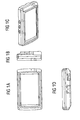
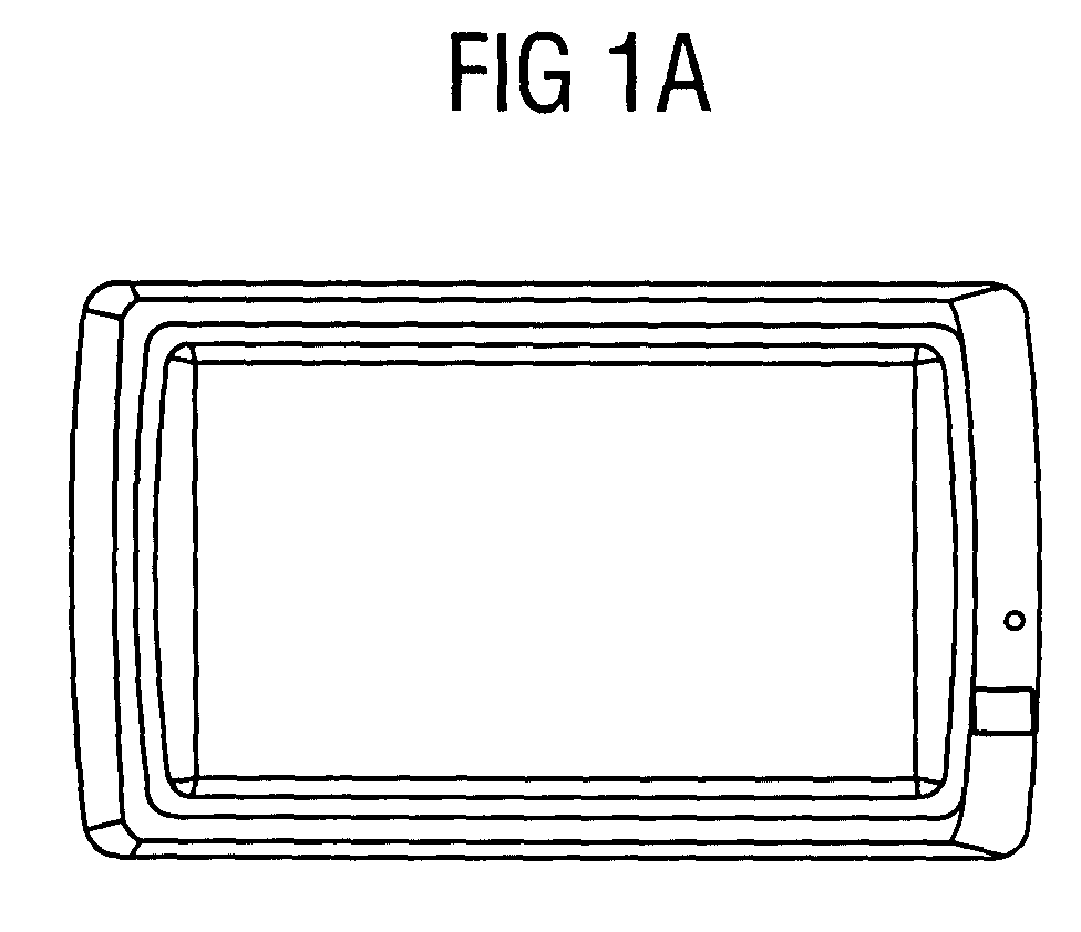
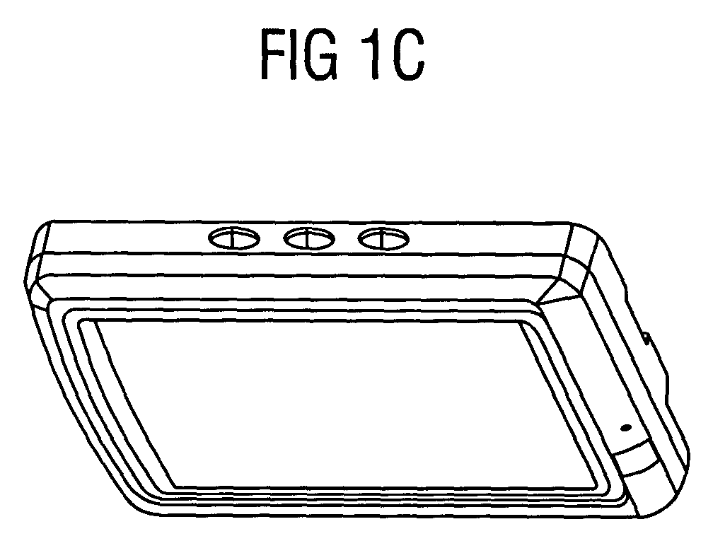
- Figures 1a-1d illustrate an example of a display device for use in a car radio or similar car-based information output apparatus.
- Figure 1a illustrates a front view of the display.
- Such display may accommodate a few lines of characters, radio station information, a road map, iconized representations of car-internal or car-external situations, or other.
- the size may be various, such as without restrictions 3 x 5 centimeters in a relatively small display, or 12 x 15 centimeters in a larger one.
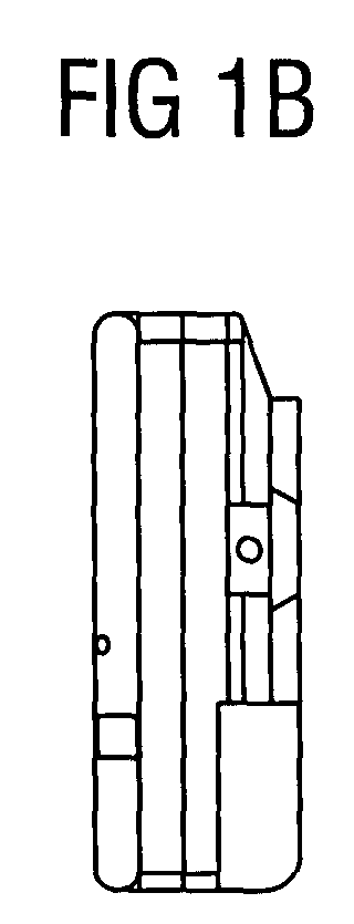
- Figure 1b shows a plan view from the shorter side, and Figure 1d from the longer side.
- Figure 1c is a perspective view. As marketed, such displays may come with drivers, decoders, power supply, data storage, and various other subsystems and peripherals that will not be further herein considered for brevity.
- Figures 2a-2d illustrate a typical car radio enclosure.
- Figure 2a shows a top plan view of the enclosure, together with indications of the size thereof: 178.6 times 150.6 millimeters.
- Figure 2c shows a front view of the device, with the display device in place.
- Figure 2d shows a side view of the car radio enclosure, and Figure 2b a perspective view of the car radio enclosure.
- Figure 2b a perspective view of the car radio enclosure.
Landscapes
- Engineering & Computer Science (AREA)
- Computer Networks & Wireless Communication (AREA)
- Signal Processing (AREA)
- Devices For Indicating Variable Information By Combining Individual Elements (AREA)
- Fittings On The Vehicle Exterior For Carrying Loads, And Devices For Holding Or Mounting Articles (AREA)
- Springs (AREA)
- Coating Apparatus (AREA)
Abstract
Description
- A mechanism for reversibly storing a display device and a car radio provided with such mechanism.
- The invention relates to a mechanism for reversibly storing a display device pertaining to a car information output apparatus, said mechanism comprising a guidance facility for providing two-way guidance for said display device along a substantially linear path, spring means for exerting an ejecting force on said display device, insert means for under control of an external force allowing insertion of said display device into said mechanism, and lock means for locking said display device after said insertion in a stored position, as has been recited in the preamble of Claim 1.
Nowadays, many car information output apparatuses come with a display device, such as car radios, route planning systems, systems providing information such as pertaining to the car proper or to other circumstances, and other.
It has been found necessary to allow reversibly storing of such a display device in the form of an LCD, TFT, Touch-screen or OLED, within the space car radio enclosure and to subsequently allow ejecting the display device out from the enclosure. This ejecting may be used for repair, maintenance, and other purposes. Such storing mechanism has been configured with an electromechanical system comprising of batteries, motors, gears, printed circuit board, wires, a mechanical frame, and other parts. This great complexity is brought about, because an electromechanical system can have various different constructions, and can in particular, store and subsequently discharge a substantial amount of energy to the system to displace the display device during insertion and during ejection, respectively. Such complexity is a marked disadvantage. - It is in principle possible to apply a single long compression spring to store and subsequently relieve compression energy. The inventor has recognized that such long spring will easily buckle and fail to be compressed according to its original intent. The inventor has furthermore recognized the possibility two use two compression strings, mounted as it were, in series. With two separate compression springs, their separate lengths can be made shorter to appreciably reduce the buckling effect.
In consequence, amongst other things, it is an object of the present invention to provide a configuration with two compression springs. Now therefore, according to one of its aspects, the invention is characterized in that said spring means comprise a first compression spring facility having a first end and a second end, and a second compression spring facility having a third end and a fourth end, and in that said mechanism comprises an intermediate member that joins said second end and said third end, so that relative travel between said first end and said fourth end determines an overall movement of said display device.
An embodiment of the invention is characterized in that said first compression spring facility has a first guide facility that is incorporated in both bracket frame and bracket sleeve therefor.
Another embodiment of the invention is characterized in that said second compression spring facility has a second guide that rests on the bracket's base at a first end of the second compression spring facility, and the other end thereof being guided by a tubular construction built from the bracket sleeve.
Yet another embodiment of the invention is characterized in that all three components bracket base, spindle guide G1 and bracket sleeve allow slotting into each other for compactness.
Preferably, said first and second compression spring facilities are screw springs.
An alternative embodiment of the invention is characterized in that
said first and second compression spring facilities are laterally disposed with respect to each other. - The invention also relates to a car radio provided with a mechanism for therein storing a display device as claimed in Claim 1. Further advantageous aspects of the invention are recited in dependent Claims.
- These and further features, aspects and advantages of the invention will be discussed more in detail hereinafter with reference to the disclosure of preferred embodiments of the invention, and in particular with reference to the appended Figures that illustrate:
- Figures 1a-1d, an example of a display device;
- Figures 2a-2d, a typical car radio enclosure;
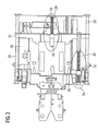
- Figure 3, a two-level ejection system embodiment according to the invention;
- Figures 4a, 4b, the first mechanism in eject mode and in store mode, respectively;
- Figures 5a, 5b, the second mechanism in eject mode and in store mode, respectively;
- Figure 6, a further view of the embodiment; Figure 7, a still further view of the embodiment.
-
- Reference will now be made to the drawings, wherein depicted elements are not necessarily shown to scale and wherein like or similar elements are designated by the same reference numeral through the several views.
Figures 1a-1d illustrate an example of a display device for use in a car radio or similar car-based information output apparatus. Herein, Figure 1a illustrates a front view of the display. Such display may accommodate a few lines of characters, radio station information, a road map, iconized representations of car-internal or car-external situations, or other. The size may be various, such as without restrictions 3 x 5 centimeters in a relatively small display, or 12 x 15 centimeters in a larger one. Figure 1b shows a plan view from the shorter side, and Figure 1d from the longer side. Finally, Figure 1c is a perspective view. As marketed, such displays may come with drivers, decoders, power supply, data storage, and various other subsystems and peripherals that will not be further herein considered for brevity.
Figures 2a-2d illustrate a typical car radio enclosure. Figure 2a shows a top plan view of the enclosure, together with indications of the size thereof: 178.6 times 150.6 millimeters. Figure 2c shows a front view of the device, with the display device in place. Figure 2d shows a side view of the car radio enclosure, and Figure 2b a perspective view of the car radio enclosure. For brevity, no further details on either the enclosure proper, or on the car radio functionality, are given here, apart from such internal constructive details as presented hereinafter.
Now, along with providing the functions of storing and ejecting the display device via a standalone mechanical system, the following two main problems will arise: - 1. Buckling of the compression spring. In particular, in order to displace the display device by more than half its length outside the car radio enclosure, a long compression spring will be needed. Such long compression spring will increase the tendency of the spring to buckle. This buckling effect will hinder both the natural operation of the spring and will reduce its reliability, and therefor, of the overall system as well.
- 2. Over-pitched compression spring. In particular, the display device, whether it is based on LCD, TFT, Touch- screen, or OLED technology, is a relatively heavy component. To then effectively move the display device, a high spring force is needed. This high force can be realized by a spring with greater pitch. However, the over-pitching of such a spring will subject the spring to excessive stress which can reduce fatigue resistance. Figure 3 shows a two-level ejection system embodiment according to the invention. For brevity, the display device itself has not been shown. The inserting force is applied from the left hand side. The mechanism is built within a
- a) Sub-system A (26), in particular made up from bracket frame (20), bracket sleeve (22), and compression spring C1 (24).
- b) Sub-system B (34): in particular made up from bracket base (36), spindle guide G1 (32), compression spring C2 (30) and bracket sleeve (22).
-
Figures 4a, 4b show a side view of the
Figures 5a, 5b show the second mechanism (34) in eject mode and in store mode, respectively. In this sub-system B, an additional spindle guide G1 (32) has the function to guide the end of the compression spring (30) resting on the bracket base (36), while the other end of the compression spring (30) is guided by the tubular construction (48) built from the bracket sleeve (22). To achieve maximum compactness, all three components, bracket base, spindle guide G1 and bracket sleeve, have been shaped so as to slot into each other (50).
The high energy needed to eject the display device can now be distributed among the two springs. Because the two compression springs are relatively short, this feature will permit the use of greater-diameter spring wire for attaining higher stiffness whilst minimizing the probability and effect of buckling.
The effect of the invention on the spring force is to allow it to be much more adjustable along with a variation in the spring wire diameter as compared to varying the compression spring pitch. As such, the pitch can be designed to the minimum value for achieving a more reliable spring life.
The bracket base runs on a first and a second hard-chrome plated
The bracket base slides with close fit along spindle S1 while a larger clearance is specified between spindle S2 and the bracket base. This close fit between spindle S1 and
Figure 6 shows a further view of the embodiment. Note that with respect to Figure 3, the Figure has been reversed in that the inserting force is applied from the right.
Figure 7 shows a still further view of the embodiment in the same orientation as Figure 6, together with an arrow indicating the inserting
The two systems have been fine-tuned, in terms of force, to provide an optimized friction condition for all sliding components mounted on the mechanism. The locations of both sub-systems have been designed to minimize the loss of force needed to eject the display device. This further lowers the requirements on the ejection spring system.
Now, the present invention has hereabove been disclosed with reference to preferred embodiments thereof. Persons skilled in the art will recognize that numerous modifications and changes may be made thereto without exceeding the scope of the appended Claims. In consequence, the embodiments should be considered as being illustrative, and no restriction should be construed from those embodiments, other than as have been recited in the Claims.
Claims (8)
- A mechanism for reversibly storing a display device pertaining to a car information output apparatus, said mechanism comprising a guidance facility for providing two-way guidance for said display device along a substantially linear path, spring means for exerting an ejecting force on said display device, insert means for under control of an external force allowing insertion of said display device into said mechanism, and lock means for locking said display device after said insertion in a stored position, said mechanism being characterized in that said spring means comprise a first compression spring facility (24) having a first end and a second end, and a second compression spring facility (30) having a third end and a fourth end, and in that said mechanism comprises an intermediate member (22) that joins said second end and said third end, so that relative travel between said first end and said fourth end determines an overall movement of said display device.
- A mechanism as claimed in Claim 1, being characterized in that said first compression spring facility (24) has a first guide facility that is incorporated in both bracket frame (40) and bracket sleeve (42) therefor (Figure 4).
- A mechanism as claimed in Claim 1, being characterized in that said second compression spring facility has a second guide that rests on the bracket's (36) base at a first end of the second compression spring facility, and the other end thereof being guided by a tubular construction built from the bracket sleeve (22).
- A mechanism as claimed in claim 3, being characterized in that all three components bracket base (36), spindle guide G1 (32) and bracket sleeve (22) allow slotting into each other for compactness.
- A mechanism as claimed in Claim 1, for application to a car radio.
- A mechanism as claimed in Claim 1, being characterized in that said first and second compression spring facilities are screw springs.
- A mechanism as claimed in Claim 1, being characterized in that said first and second compression spring facilities are laterally disposed with respect to each other.
- A car radio provided with a mechanism for therein storing a display device as claimed in Claim
Applications Claiming Priority (2)
| Application Number | Priority Date | Filing Date | Title |
|---|---|---|---|
| US39246602P | 2002-06-28 | 2002-06-28 | |
| US392466P | 2002-06-28 |
Publications (2)
| Publication Number | Publication Date |
|---|---|
| EP1385271A1 true EP1385271A1 (en) | 2004-01-28 |
| EP1385271B1 EP1385271B1 (en) | 2009-04-22 |
Family
ID=30000875
Family Applications (1)
| Application Number | Title | Priority Date | Filing Date |
|---|---|---|---|
| EP03012733A Expired - Lifetime EP1385271B1 (en) | 2002-06-28 | 2003-06-04 | Car radio with removable front |
Country Status (5)
| Country | Link |
|---|---|
| US (1) | US20040001055A1 (en) |
| EP (1) | EP1385271B1 (en) |
| AU (1) | AU2003256219A1 (en) |
| DE (1) | DE60327288D1 (en) |
| WO (1) | WO2004004142A2 (en) |
Families Citing this family (2)
| Publication number | Priority date | Publication date | Assignee | Title |
|---|---|---|---|---|
| FR2901207A1 (en) * | 2006-05-16 | 2007-11-23 | Viamichelin Soc Par Actions Si | DEVICE SUPPORTING PARTICULARLY FOR PORTABLE APPARATUS |
| US9955802B2 (en) | 2015-04-08 | 2018-05-01 | Fasteners For Retail, Inc. | Divider with selectively securable track assembly |
Citations (2)
| Publication number | Priority date | Publication date | Assignee | Title |
|---|---|---|---|---|
| US5510957A (en) * | 1994-03-14 | 1996-04-23 | Alpine Electronics, Inc. | Locking and retaining mechnism for an electronic device having a detachable control unit |
| US5953302A (en) * | 1996-05-27 | 1999-09-14 | Clarion Co., Ltd. | Recorded medium playback device with removable panel and having a lever contacting panel and detection switch |
Family Cites Families (14)
| Publication number | Priority date | Publication date | Assignee | Title |
|---|---|---|---|---|
| US1066518A (en) * | 1911-07-24 | 1913-07-08 | Egry Register Co | Cash-drawer. |
| US2813771A (en) * | 1955-06-24 | 1957-11-19 | Selmer Alois | Garbage disposal unit |
| JPS5971707A (en) * | 1982-10-19 | 1984-04-23 | 株式会社ニフコ | Apparatus for storing unit case |
| DE3300926C2 (en) * | 1983-01-13 | 1986-11-13 | Audi AG, 8070 Ingolstadt | Storage containers, in particular for motor vehicles |
| EP0141937B1 (en) * | 1983-08-29 | 1989-03-22 | idn inventions and development of novelties ag | Device for storing substantially disc-shaped record carriers |
| US5161028A (en) * | 1989-07-20 | 1992-11-03 | Kabushiki Kaisha Toshiba | Car-mounted video displaying apparatus |
| JP2547102B2 (en) * | 1989-12-15 | 1996-10-23 | クラリオン株式会社 | Liquid crystal display device with slide storage |
| US5847685A (en) * | 1992-08-19 | 1998-12-08 | Alpine Electronics, Inc. | Vehicle-mounted display mechanism |
| US5524859A (en) * | 1994-02-08 | 1996-06-11 | Squires; Carlton G. | Security mounting for audio equipment in a motor vehicle |
| GB2322105B (en) * | 1997-02-06 | 1999-08-18 | Nissan Motor | Vehicle display layout structure |
| GB2336248A (en) * | 1998-04-08 | 1999-10-13 | Ibm | Accessory mounting for digital computer |
| US6816177B2 (en) * | 2002-01-28 | 2004-11-09 | Tony Wang | Display observation angle of which is multidirectionally adjustable |
| US6754070B2 (en) * | 2002-03-15 | 2004-06-22 | E-Lead Electronic Co., Ltd. | Car use computer |
| US6837581B1 (en) * | 2002-07-29 | 2005-01-04 | Raytheon Company | System and method for deploying a mirror assembly of a display unit |
-
2003
- 2003-06-04 DE DE60327288T patent/DE60327288D1/en not_active Expired - Fee Related
- 2003-06-04 EP EP03012733A patent/EP1385271B1/en not_active Expired - Lifetime
- 2003-06-27 WO PCT/SG2003/000155 patent/WO2004004142A2/en not_active Ceased
- 2003-06-27 AU AU2003256219A patent/AU2003256219A1/en not_active Abandoned
- 2003-06-30 US US10/610,738 patent/US20040001055A1/en not_active Abandoned
Patent Citations (2)
| Publication number | Priority date | Publication date | Assignee | Title |
|---|---|---|---|---|
| US5510957A (en) * | 1994-03-14 | 1996-04-23 | Alpine Electronics, Inc. | Locking and retaining mechnism for an electronic device having a detachable control unit |
| US5953302A (en) * | 1996-05-27 | 1999-09-14 | Clarion Co., Ltd. | Recorded medium playback device with removable panel and having a lever contacting panel and detection switch |
Also Published As
| Publication number | Publication date |
|---|---|
| EP1385271B1 (en) | 2009-04-22 |
| US20040001055A1 (en) | 2004-01-01 |
| WO2004004142A3 (en) | 2004-04-08 |
| DE60327288D1 (en) | 2009-06-04 |
| WO2004004142A2 (en) | 2004-01-08 |
| AU2003256219A1 (en) | 2004-01-19 |
Similar Documents
| Publication | Publication Date | Title |
|---|---|---|
| US9188781B2 (en) | Combiner storage device, head-up display device | |
| US8118378B2 (en) | Rail assembly | |
| US6490122B1 (en) | System and method for providing power and control signals to a cartridge access device in a cartridge storage system | |
| CN100411906C (en) | Slide for seat of vehicle | |
| US5028083A (en) | Latch assembly | |
| EP1406174A3 (en) | Methods and mechanisms for proactive memory management | |
| US7646866B2 (en) | Slide module for a slide type electronic device | |
| JP4509977B2 (en) | Slide module and mobile communication terminal having the same | |
| US6351378B1 (en) | Fixing device of a disk driver | |
| EP1385271B1 (en) | Car radio with removable front | |
| US6690574B2 (en) | Electronic apparatus | |
| EP1832529A3 (en) | Storage and retrieval device with intermediate storage unit in a shelving storage facility comprising slides in the shelves | |
| AU2003247261A1 (en) | Toy vehicle for guided motor-racing circuits | |
| EP1915924B1 (en) | Storage panel guiding device with a magnetic damper | |
| WO2004007331A3 (en) | Conical spring buffer for an elevator | |
| JP2010280396A (en) | Shock absorber, storage medium holding device, and storage medium storage system | |
| JP2954166B1 (en) | Battery holding structure for portable radio | |
| EP1923874A1 (en) | Optical pickup guide mechanism | |
| JP7577397B1 (en) | Guide member and stiffness adjustment device for skis | |
| EP2929806B1 (en) | System comprising a slide rail assembly | |
| US6941569B2 (en) | System and method utilizing a conductive brush for providing power signals to a cartridge access device | |
| CN224217185U (en) | Temporary stop board and vehicle | |
| CN223237523U (en) | Display module assembly, on-vehicle seat and car | |
| CN1819030B (en) | Driver device and tape drive actuating system | |
| CN210109925U (en) | Intelligent point exchanging machine used in supermarket |
Legal Events
| Date | Code | Title | Description |
|---|---|---|---|
| PUAI | Public reference made under article 153(3) epc to a published international application that has entered the european phase |
Free format text: ORIGINAL CODE: 0009012 |
|
| AK | Designated contracting states |
Kind code of ref document: A1 Designated state(s): AT BE BG CH CY CZ DE DK EE ES FI FR GB GR HU IE IT LI LU MC NL PT RO SE SI SK TR |
|
| AX | Request for extension of the european patent |
Extension state: AL LT LV MK |
|
| 17P | Request for examination filed |
Effective date: 20040216 |
|
| AKX | Designation fees paid |
Designated state(s): DE FR GB IT |
|
| RAP1 | Party data changed (applicant data changed or rights of an application transferred) |
Owner name: CONTINENTAL AUTOMOTIVE GMBH |
|
| 17Q | First examination report despatched |
Effective date: 20080901 |
|
| GRAP | Despatch of communication of intention to grant a patent |
Free format text: ORIGINAL CODE: EPIDOSNIGR1 |
|
| GRAP | Despatch of communication of intention to grant a patent |
Free format text: ORIGINAL CODE: EPIDOSNIGR1 |
|
| GRAS | Grant fee paid |
Free format text: ORIGINAL CODE: EPIDOSNIGR3 |
|
| GRAA | (expected) grant |
Free format text: ORIGINAL CODE: 0009210 |
|
| AK | Designated contracting states |
Kind code of ref document: B1 Designated state(s): DE FR GB IT |
|
| REG | Reference to a national code |
Ref country code: GB Ref legal event code: FG4D |
|
| REF | Corresponds to: |
Ref document number: 60327288 Country of ref document: DE Date of ref document: 20090604 Kind code of ref document: P |
|
| PGFP | Annual fee paid to national office [announced via postgrant information from national office to epo] |
Ref country code: FR Payment date: 20090615 Year of fee payment: 7 |
|
| PGFP | Annual fee paid to national office [announced via postgrant information from national office to epo] |
Ref country code: GB Payment date: 20090618 Year of fee payment: 7 Ref country code: DE Payment date: 20090630 Year of fee payment: 7 |
|
| PLBE | No opposition filed within time limit |
Free format text: ORIGINAL CODE: 0009261 |
|
| STAA | Information on the status of an ep patent application or granted ep patent |
Free format text: STATUS: NO OPPOSITION FILED WITHIN TIME LIMIT |
|
| 26N | No opposition filed |
Effective date: 20100125 |
|
| PGFP | Annual fee paid to national office [announced via postgrant information from national office to epo] |
Ref country code: IT Payment date: 20090620 Year of fee payment: 7 |
|
| GBPC | Gb: european patent ceased through non-payment of renewal fee |
Effective date: 20100604 |
|
| REG | Reference to a national code |
Ref country code: FR Ref legal event code: ST Effective date: 20110228 |
|
| PG25 | Lapsed in a contracting state [announced via postgrant information from national office to epo] |
Ref country code: IT Free format text: LAPSE BECAUSE OF NON-PAYMENT OF DUE FEES Effective date: 20100604 |
|
| PG25 | Lapsed in a contracting state [announced via postgrant information from national office to epo] |
Ref country code: DE Free format text: LAPSE BECAUSE OF NON-PAYMENT OF DUE FEES Effective date: 20110101 |
|
| PG25 | Lapsed in a contracting state [announced via postgrant information from national office to epo] |
Ref country code: FR Free format text: LAPSE BECAUSE OF NON-PAYMENT OF DUE FEES Effective date: 20100630 |
|
| PG25 | Lapsed in a contracting state [announced via postgrant information from national office to epo] |
Ref country code: GB Free format text: LAPSE BECAUSE OF NON-PAYMENT OF DUE FEES Effective date: 20100604 |