EP1385262B1 - Mobile terminal with electromagnetic actuator - Google Patents
Mobile terminal with electromagnetic actuator Download PDFInfo
- Publication number
- EP1385262B1 EP1385262B1 EP02722803A EP02722803A EP1385262B1 EP 1385262 B1 EP1385262 B1 EP 1385262B1 EP 02722803 A EP02722803 A EP 02722803A EP 02722803 A EP02722803 A EP 02722803A EP 1385262 B1 EP1385262 B1 EP 1385262B1
- Authority
- EP
- European Patent Office
- Prior art keywords
- portable terminal
- signal
- electromagnetic induction
- terminal
- amplifier
- Prior art date
- Legal status (The legal status is an assumption and is not a legal conclusion. Google has not performed a legal analysis and makes no representation as to the accuracy of the status listed.)
- Expired - Lifetime
Links
Images


Classifications
-
- G—PHYSICS
- G07—CHECKING-DEVICES
- G07D—HANDLING OF COINS OR VALUABLE PAPERS, e.g. TESTING, SORTING BY DENOMINATIONS, COUNTING, DISPENSING, CHANGING OR DEPOSITING
- G07D9/00—Counting coins; Handling of coins not provided for in the other groups of this subclass
-
- B—PERFORMING OPERATIONS; TRANSPORTING
- B06—GENERATING OR TRANSMITTING MECHANICAL VIBRATIONS IN GENERAL
- B06B—METHODS OR APPARATUS FOR GENERATING OR TRANSMITTING MECHANICAL VIBRATIONS OF INFRASONIC, SONIC, OR ULTRASONIC FREQUENCY, e.g. FOR PERFORMING MECHANICAL WORK IN GENERAL
- B06B1/00—Methods or apparatus for generating mechanical vibrations of infrasonic, sonic, or ultrasonic frequency
- B06B1/02—Methods or apparatus for generating mechanical vibrations of infrasonic, sonic, or ultrasonic frequency making use of electrical energy
- B06B1/0207—Driving circuits
-
- H—ELECTRICITY
- H04—ELECTRIC COMMUNICATION TECHNIQUE
- H04M—TELEPHONIC COMMUNICATION
- H04M1/00—Substation equipment, e.g. for use by subscribers
- H04M1/02—Constructional features of telephone sets
- H04M1/03—Constructional features of telephone transmitters or receivers, e.g. telephone hand-sets
-
- H—ELECTRICITY
- H04—ELECTRIC COMMUNICATION TECHNIQUE
- H04M—TELEPHONIC COMMUNICATION
- H04M1/00—Substation equipment, e.g. for use by subscribers
- H04M1/60—Substation equipment, e.g. for use by subscribers including speech amplifiers
-
- H—ELECTRICITY
- H04—ELECTRIC COMMUNICATION TECHNIQUE
- H04R—LOUDSPEAKERS, MICROPHONES, GRAMOPHONE PICK-UPS OR LIKE ACOUSTIC ELECTROMECHANICAL TRANSDUCERS; ELECTRIC HEARING AIDS; PUBLIC ADDRESS SYSTEMS
- H04R9/00—Transducers of moving-coil, moving-strip, or moving-wire type
- H04R9/10—Telephone receivers
-
- B—PERFORMING OPERATIONS; TRANSPORTING
- B06—GENERATING OR TRANSMITTING MECHANICAL VIBRATIONS IN GENERAL
- B06B—METHODS OR APPARATUS FOR GENERATING OR TRANSMITTING MECHANICAL VIBRATIONS OF INFRASONIC, SONIC, OR ULTRASONIC FREQUENCY, e.g. FOR PERFORMING MECHANICAL WORK IN GENERAL
- B06B2201/00—Indexing scheme associated with B06B1/0207 for details covered by B06B1/0207 but not provided for in any of its subgroups
- B06B2201/50—Application to a particular transducer type
- B06B2201/52—Electrodynamic transducer
- B06B2201/53—Electrodynamic transducer with vibrating magnet or coil
-
- B—PERFORMING OPERATIONS; TRANSPORTING
- B06—GENERATING OR TRANSMITTING MECHANICAL VIBRATIONS IN GENERAL
- B06B—METHODS OR APPARATUS FOR GENERATING OR TRANSMITTING MECHANICAL VIBRATIONS OF INFRASONIC, SONIC, OR ULTRASONIC FREQUENCY, e.g. FOR PERFORMING MECHANICAL WORK IN GENERAL
- B06B2201/00—Indexing scheme associated with B06B1/0207 for details covered by B06B1/0207 but not provided for in any of its subgroups
- B06B2201/70—Specific application
Definitions
- This invention deals with a portable terminal in which is mounted an electromagnetic induction actuator that produces a communicant voice, a buzz, a melody or a low frequency vibration, in accordance with the frequency of an electric signal.
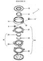
- an electromagnetic induction actuator 1 shown in figure 8 , has been proposed and put into practical use.
- this electromagnetic induction actuator 1 a plate magnet 24, a yoke 25 and a pole piece 23 make up a magnetic circuit 9 that is supported by two leaf-spring suspensions 21, 22 within a cylindrical housing 19 to constitute a magnetic vibration system 6.
- a voice coil 8 is attached to a diaphragm 18 that is fitted and fixed into the open end of the housing 19, input terminals are formed by placing terminal fittings 3, 3' on a terminal seat 20 that projects outward from the side of the housing 19, and the voice coil 8 is connected electrically to the terminal fittings 3, 3'.
- this extraneous tone may cause the user to sense a lack of rigidity in the case of his portable terminal, or give the false impression of a malfunction or improper mounting of parts within the portable terminal.
- the present inventors have devised a portable terminal in which is mounted an extraneous tone reduction device to dampen the vibration of the mechanical vibration system. They have a further goal of providing an extraneous tone reduction device by an inexpensive and simple means, and thereby prevent increases in the cost or size of the portable terminal.
- This invention also provides a portable terminal with the features of claim 1
- a signal generation source electrically connected to the amplifier may be provided which outputs a constant-voltage signal and a constant-frequency signal to the amplifier.
- Figure 1 is a schematic diagram showing the internal construction of portable terminal of an example which does not belong to the invention.
- Figure 2 is a graph showing the oscillation characteristics of the mechanical vibration system inside the electromagnetic induction actuator as measured at the outer case of the terminal equipment.
- Figure 3 is an oblique sketch of the mechanical vibration system and voice coil of the electromagnetic induction actuator when the mechanical switch is open.
- Figure 4 is an oblique sketch of the mechanical vibration system and voice coil of the electromagnetic induction actuator when the mechanical switch is closed.
- Figure 5 is a circuit diagram showing the internal construction of a portable terminal in which is mounted an extraneous tone reduction device in which a transistor is used in the mechanical switch of figure 1 .
- Figure 6 is a schematic circuit diagram showing the internal construction of portable terminal of an example of implementation of this invention.
- Figure 7 is a schematic circuit diagram showing the internal construction of portable terminal of a second example of implementation of this invention.
- Figure 8 is a schematic oblique drawing showing the electromagnetic induction actuator.
- FIG. 1 is a schematic diagram showing the internal construction of portable terminal of the first example of implementation of this invention
- figure 2 is a graph showing the oscillation characteristics of the mechanical vibration system inside the electromagnetic induction actuator as measured at the outer case of the terminal equipment.
- an electromagnetic induction actuator 1 and a mechanical switch 2 that is the switching means that short circuits the terminal fittings 3, 3' are mounted within the outer case 5, indicated by the broken line, of the portable terminal 4.
- the mechanical switch 2 is in the open state, which is equivalent to the internal structure of the conventional portable terminal.
- the vibration of the case causes the mechanical vibration system within the electromagnetic induction actuator 1 to vibrate.
- the mechanical vibration system is flexibly supported by two leaf-spring suspensions, and so a graph of the oscillation characteristics of the mechanical vibration system shows gradual convergence and attenuation over time.
- the broken line curve in figure 2 shows the oscillation characteristics measured through the outer case 5. Vibrating as shown by the broken line curve, the mechanical vibration system causes the air to quiver, producing an extraneous tone similar to a snapped string.
- Figures 3 and 4 are oblique sketches that show the states of the mechanical vibration system and voice coil of the electromagnetic induction actuator.
- the mechanical vibration system 6 vibrates up and down in the direction of arrow 7.
- electromagnetic induction occurs between the magnetic circuit 9 of the mechanical vibration system 6 and the voice coil 8 that is electrically connected to the terminal fittings, and induced electromotive force is created in the voice coil 8. Because the mechanical vibration system 6 vibrates up and down, the direction of the induced electromotive force keeps changing back and forth with each cycle.
- the mechanical switch 2 can be made using a transistor as shown in figure 5 , an FET or other semiconductor element with a switching action, or a relay or other excited contact device. It is also possible to form an analog switch of various semiconductor devices and use that as the mechanical switch. It is also possible, needless to say, to obtain the same effect using an IC that incorporates an analog switch.
- the example of implementation of the portable terminal of this invention is explained in detail below, with reference to the circuit diagram of figure 6 .
- the internal structure, operation and functions of the electromagnetic induction actuator 1 are the same as shown in figure 8 ; duplicative explanation is omitted.
- the explanation of this example of implementation is based on the assumption that the electromagnetic induction actuator 1 is not in the operating state; that is, that the portable terminal 4 is in the state of awaiting an incoming call.
- the extraneous tone reduction device of figure 6 comprises the electromagnetic induction actuator 1, and two amplifiers 13, 13' that are electrically connected to the terminal fitting 3 (and 3') respectively.
- Amplifiers have been mounted in conventional portable terminals as well, but when those terminals are in the state of awaiting an incoming call, the voltage to the amplifiers is turned down, and their function is essentially stopped. This example of implementation is set so that voltage is always applied to the amplifiers 13, 13' and they are in an operating state.
- the signal 14 is input as feedback to the amplifier 13'; the voltage value of the output signal 15' changes to -V[V] and is input to the terminal fitting 3'.
- a closed circuit is formed between the voice coil (not illustrated) and the two amplifier circuits 13, 13', the induction current flows in the voice coil and a magnetic field is created.
- the direction of this magnetic field 11 suppresses the oscillations of the mechanical vibration system and cause convergence at zero, thus reducing the extraneous tone by the same principle as in the first example of implementation.
- the two amplifier circuits 13, 13' adjust their output signals 15, 15' to 0[V], which restores the original quiet state of the electromagnetic induction actuator, with the voltage values of the signals 14, 14' returned to 0[V]. It can be seen from the above that connecting amplifiers, which are normally set in the operating state by application of a voltage, to the electromagnetic induction actuator is effective in reduction of the extraneous tone.
- the oscillation characteristics of the mechanical vibration system measured through the outer case 5 measure almost the same as the curve shown by the solid line in figure 2 . Accordingly, the sense of reverberation in the audible period is greatly diminished and in this way, the user's awareness is that the extraneous tone is reduced.
- the extraneous tone reduction device has, in addition to the circuit constitution shown in figure 6 , a signal generator source 16 that is electrically connected to one amplifier 13 to output a signal to it; the device is mounted inside the outer case 5 of the portable terminal 4.
- the amplifiers 13, 13' are always set in an operating state with voltage applied, and the explanation assumes a state in which the electromagnetic induction actuator 1 is not operating; that is, that the portable terminal 4 is in the state of awaiting a call.
- the following explanation concerns the overall operation of the portable terminal when the signal generation source 16 generates a constant-voltage signal 17, and the portable terminal 4 in which this device is mounted.
- the constant-voltage signal 17 is amplified by the amplifiers 13, 13' and input to the terminal fittings 3, 3' of the electromagnetic induction actuator 1.
- the voltage value of the output signals 15, 15' at that time is expressed as V[V] for convenience of explanation.
- This electromotive force is found on the two terminal fittings 3, 3' that are electrically connected to the voice coil , and so the voltage value of one of the signals 14, 14' found on the terminal fittings 3, 3' changes from V[V] to V'[V], and the voltage values of the signals 14, 14' are unbalanced between the two input terminals.
- a closed circuit is formed between the voice coil (not illustrated) and the two amplifiers 13, 13', an induced current flows through the voice coil, and a magnetic field is created, so that the vibration of the mechanical vibration system is suppressed and converges on zero, and the extraneous tone is reduced.
- this example of implementation makes it possible to achieve an extraneous tone reduction effect from the operation of the amplifiers 13, 13'.
- This operation is explained below.
- the input side of amplifier 13 is always maintained at a fixed voltage value from the constant-voltage signal 17, and so the output signal 15 gradually changes from V'[V] to V[V]. Because of this output signal 15, the signal 14 also changes to V[V]. Then, by inputting the signal 14 to the amplifier circuit 13' as feedback, the output signal 15' is changed to -V[V], and when the signal 15' is applied, the signal 14' also changes to -V[V].
- the two amplifiers 13, 13' adjust their output signals 15, 15' to V[V] and -V[V], and by that means the electromagnetic induction actuator 1 is returned to its original quiet characteristics, with the signals 14, 14' having voltage values of V[V] and -V[V].
- connecting amplifiers which are normally set in the operating state by application of a voltage, to the electromagnetic induction actuator and inputting a constant-voltage signal to the amplifiers is effective in reduction of the extraneous tone.
- the oscillation characteristics of the mechanical vibration system measured through the outer case 5 measure almost the same as the curve shown by the solid line in figure 2 . Accordingly, the sense of reverberation in the audible period is greatly diminished and in this way, the user's awareness is that the extraneous tone is reduced.
- One standard for the voltage value of the constant-voltage signal 17 is to have a voltage value such that, when the signal 17 is amplified and input to operate the electromagnetic induction actuator 1, it drives the electromagnetic induction actuator 1 without the user of the portable terminal being aware of that operation. That is, the voltage value should be smaller than the voltage value that performs the incoming call notification operation of the electromagnetic induction actuator 1 (hereafter the operating voltage).
- the value of the operating voltage can vary, depending on the type, size, weight and model of the electromagnetic induction actuator 1. Consequently, it is not possible to make a blanket statement that the voltage value of the constant-voltage signal should be less than any specific voltage. As stated above, it is preferable to set that value with reference to the operating voltage of the electromagnetic induction actuator 1.
- a constant-voltage signal is amplified and applied to the terminal fittings, but the same effect can be had by amplifying the voltage of a constant-frequency signal, which has a fixed frequency, and applying that to the terminal fittings instead of a constant-voltage signal.
- the constant-frequency signal is produced by the signal generator 16.
- One standard for the frequency range of the constant-frequency signal is to set the range that will allow operation at a level that will not be noticed by the user of the portable terminal 4 when the electromagnetic induction actuator 1 operates.
- the frequency should be set, therefore, outside the operating range of the electromagnetic induction actuator 1.
- that operating range will vary depending on the type, size, weight and model of the electromagnetic induction actuator 1; a blanket decision is not possible, and no one specific frequency can be specified as the appropriate frequency rang for the constant-frequency signal.
- it is preferable to set the range outside the 20[Hz] to 20[kHz] range generally know as the frequency range audible to humans, but because the audible range varies from person to person, a blanket decision is not possible.
- amplifiers conventionally mounted in the portable terminal are used for reduction of the extraneous tone by means of constant operation. Adding no new parts to the portable terminal except a vibration generator, it is possible to reduce the extraneous tone while minimizing increases to the size or cost of the portable terminal.
- this invention it is possible to reduce the extraneous tone when a portable terminal is in the state of awaiting an incoming call, and it is also possible to realize an extraneous tone reduction device in which only one new part-- a mechanical switch or a source of vibration-- is mounted in the portable terminal, or to realize an extraneous tone reduction device that uses amplifiers already mounted in the portable terminal without mounting any new parts. It is possible, accordingly, to hold to a minimum any increase in the size or cost of the portable terminal, and to provide an inexpensive and highly reliable extraneous tone reduction device and a portable terminal in which such a device is mounted.
Landscapes
- Engineering & Computer Science (AREA)
- Signal Processing (AREA)
- Physics & Mathematics (AREA)
- Mechanical Engineering (AREA)
- Acoustics & Sound (AREA)
- General Physics & Mathematics (AREA)
- Apparatuses For Generation Of Mechanical Vibrations (AREA)
- Telephone Function (AREA)
- Telephone Set Structure (AREA)
- Details Of Audible-Bandwidth Transducers (AREA)
- Circuit For Audible Band Transducer (AREA)
- Reciprocating, Oscillating Or Vibrating Motors (AREA)
Description
- This invention deals with a portable terminal in which is mounted an electromagnetic induction actuator that produces a communicant voice, a buzz, a melody or a low frequency vibration, in accordance with the frequency of an electric signal.
- In recent years the growing popularity of portable terminals, as represented by portable telephones, has been remarkable. As means of incoming call notification, these portable terminals have been fitted, normally, with small, cylindrical motors for generation of vibrations to be sensed by the body, transducers to create a buzzing sound, and speakers used for communicant voice signals.
- Because there is generally a strong preference for miniaturized portable terminals, efforts have been made to reduce the number of parts mounted within the terminals. As a specific example, an
electromagnetic induction actuator 1, shown infigure 8 , has been proposed and put into practical use. In thiselectromagnetic induction actuator 1, aplate magnet 24, ayoke 25 and apole piece 23 make up amagnetic circuit 9 that is supported by two leaf-spring suspensions cylindrical housing 19 to constitute amagnetic vibration system 6. - A
voice coil 8 is attached to adiaphragm 18 that is fitted and fixed into the open end of thehousing 19, input terminals are formed by placingterminal fittings 3, 3' on aterminal seat 20 that projects outward from the side of thehousing 19, and thevoice coil 8 is connected electrically to theterminal fittings 3, 3'. - By changing the frequency of the electric signal applied to the
voice coil 8, it is possible to drive either one or both of thediaphragm 18 and themechanical vibration system 6, such that thediaphragm 18 produces a buzzer sound, melodies or communicant voice and themechanical vibration system 6 produces a vibration sensed by the body. That is, because it is possible to produce a vibration sensed by the body, communicant voice, and a buzzer sound or melodies with asingle actuator 1, it is possible to reduce the number of mechanisms mounted in portable terminals. - However, when a portable terminal in which this
electromagnetic induction actuator 1 is mounted is awaiting an incoming call, that is, when the electromagnetic induction actuator is not operating, a tap on the outer case of the portable terminal will cause the mechanical vibration system to oscillate and produce the sound of a snapped string (hereafter this sound is referred to as an extraneous tone). This extraneous tone may cause the user to sense a lack of rigidity in the case of his portable terminal, or give the false impression of a malfunction or improper mounting of parts within the portable terminal. - For that reason, the present inventors have devised a portable terminal in which is mounted an extraneous tone reduction device to dampen the vibration of the mechanical vibration system. They have a further goal of providing an extraneous tone reduction device by an inexpensive and simple means, and thereby prevent increases in the cost or size of the portable terminal.
- This invention also provides a portable terminal with the features of claim 1 A signal generation source electrically connected to the amplifier, may be provided which outputs a constant-voltage signal and a constant-frequency signal to the amplifier.
-
Figure 1 is a schematic diagram showing the internal construction of portable terminal of an example which does not belong to the invention. -
Figure 2 is a graph showing the oscillation characteristics of the mechanical vibration system inside the electromagnetic induction actuator as measured at the outer case of the terminal equipment. -
Figure 3 is an oblique sketch of the mechanical vibration system and voice coil of the electromagnetic induction actuator when the mechanical switch is open. -
Figure 4 is an oblique sketch of the mechanical vibration system and voice coil of the electromagnetic induction actuator when the mechanical switch is closed. -
Figure 5 is a circuit diagram showing the internal construction of a portable terminal in which is mounted an extraneous tone reduction device in which a transistor is used in the mechanical switch offigure 1 . -
Figure 6 is a schematic circuit diagram showing the internal construction of portable terminal of an example of implementation of this invention. -
Figure 7 is a schematic circuit diagram showing the internal construction of portable terminal of a second example of implementation of this invention. -
Figure 8 is a schematic oblique drawing showing the electromagnetic induction actuator. - First Example , which does not belong to the invention: The first example of the portable terminal of this invention is explained in detail below, with reference to
figures 1 through 4 .Figure 1 is a schematic diagram showing the internal construction of portable terminal of the first example of implementation of this invention, andfigure 2 is a graph showing the oscillation characteristics of the mechanical vibration system inside the electromagnetic induction actuator as measured at the outer case of the terminal equipment. As shown infigure 1 , anelectromagnetic induction actuator 1 and amechanical switch 2 that is the switching means that short circuits theterminal fittings 3, 3' are mounted within theouter case 5, indicated by the broken line, of theportable terminal 4. The following explanation of this example of implementation is based on the assumption that theelectromagnetic induction actuator 1 is not in the operating state; that is, theportable terminal 4 is in the state of awaiting an incoming call. Now, the internal structure, operation and functions of theelectromagnetic induction actuator 1 are the same as shown infigure 8 ; duplicative explanation is omitted. - The principle behind production of an extraneous tone will be explained first. In
figure 1 , themechanical switch 2 is in the open state, which is equivalent to the internal structure of the conventional portable terminal. When theouter case 5 is tapped in this state, the vibration of the case causes the mechanical vibration system within theelectromagnetic induction actuator 1 to vibrate. As described above, the mechanical vibration system is flexibly supported by two leaf-spring suspensions, and so a graph of the oscillation characteristics of the mechanical vibration system shows gradual convergence and attenuation over time. The broken line curve infigure 2 shows the oscillation characteristics measured through theouter case 5. Vibrating as shown by the broken line curve, the mechanical vibration system causes the air to quiver, producing an extraneous tone similar to a snapped string. - Next, while explaining the principle of reduction of the extraneous tone, the structure and operation of a concrete device will be explained.
Figures 3 and 4 are oblique sketches that show the states of the mechanical vibration system and voice coil of the electromagnetic induction actuator. When the outer case is tapped as described above, themechanical vibration system 6 vibrates up and down in the direction ofarrow 7. With that, electromagnetic induction occurs between themagnetic circuit 9 of themechanical vibration system 6 and thevoice coil 8 that is electrically connected to the terminal fittings, and induced electromotive force is created in thevoice coil 8. Because themechanical vibration system 6 vibrates up and down, the direction of the induced electromotive force keeps changing back and forth with each cycle. - When the
mechanical switch 2 is open, as infigure 3 , the terminal fittings (not illustrated) are opened and so the induced electromotive force generated in thevoice coil 8 does not flow as an induced current. Consequently no magnetic field is produced by the induced current. When themechanical switch 2 is closed as infigure 4 , however, there is a closed circuit between thevoice coil 8 and themechanical switch 2, and so the inducedcurrent 10 flows through thevoice coil 8 and generates amagnetic field 11. The direction of thismagnetic field 11 counters the direction of vibration of the magnetic circuit, and so the up and down oscillations of the mechanical vibration system are suppressed and converge quickly. The curve of the oscillation characteristics, as measured through the outer case, is shown by the solid line infigure 2 . Asfigure 2 indicates, the oscillation characteristics when themechanical switch 2 is closed (the terminal fittings are short-circuited) converge at zero more quickly than the oscillation characteristics when it is open, and so the sense of reverberation in the audible period is greatly diminished. In this way, the user's awareness is that the extraneous tone is reduced. - Now, the
mechanical switch 2 can be made using a transistor as shown infigure 5 , an FET or other semiconductor element with a switching action, or a relay or other excited contact device. It is also possible to form an analog switch of various semiconductor devices and use that as the mechanical switch. It is also possible, needless to say, to obtain the same effect using an IC that incorporates an analog switch. - Using this example of implementation, it is possible to reduce the extraneous tone when the portable terminal is awaiting an incoming call, and by limiting the additional parts required to realize the extraneous tone reduction device to the one mechanical switch, it is possible to minimize any increase to the size or cost of the portable terminal. By using a mechanical switch that is widely known and structure is simple, it is possible to provide a portable terminal in which is mounted an extraneous tone reduction device with a switching function that is inexpensive and highly reliable.
- Example of Implementation of the invention. The example of implementation of the portable terminal of this invention is explained in detail below, with reference to the circuit diagram of
figure 6 . Now, the internal structure, operation and functions of theelectromagnetic induction actuator 1 are the same as shown infigure 8 ; duplicative explanation is omitted. The explanation of this example of implementation is based on the assumption that theelectromagnetic induction actuator 1 is not in the operating state; that is, that theportable terminal 4 is in the state of awaiting an incoming call. The extraneous tone reduction device offigure 6 comprises theelectromagnetic induction actuator 1, and twoamplifiers 13, 13' that are electrically connected to the terminal fitting 3 (and 3') respectively. - Amplifiers have been mounted in conventional portable terminals as well, but when those terminals are in the state of awaiting an incoming call, the voltage to the amplifiers is turned down, and their function is essentially stopped. This example of implementation is set so that voltage is always applied to the
amplifiers 13, 13' and they are in an operating state. - The operation of a portable terminal constituted in this way is explained below. In a quiet state with no outside force applied to the
outer case 5, there is no signal input to theamplifiers 13, 13', and so the voltage value of theoutput signals 15, 15' is maintained at 0[V]. The voltage value of the signal found at the terminal fitting 3 (and 3') of theelectromagnetic induction actuator 1 is also maintained at 0[V]. When vibration is applied by a tap on theouter case 5, the vibration is passed to the extraneous noise reduction device inside theouter case 5, and the mechanical vibration system (not illustrated) within theelectromagnetic induction actuator 1 vibrates. - Because of this vibration, there is electromagnetic induction between the magnetic circuit of the mechanical vibration system and the voice coil, and an induced electromagnetic force is generated in the voice coil. When this induced electromagnetic force is found on the
terminal fittings 3, 3', the voltage value of one side or the other ofsignal 14, 14' changes from 0[V] to a value of V[V], for a voltage imbalance between the two input terminals. In this way the voltage value of thesignal 14 changes from 0[V] to V [V]. - Then the
signal 14 is input as feedback to the amplifier 13'; the voltage value of the output signal 15' changes to -V[V] and is input to the terminal fitting 3'. In that way, a closed circuit is formed between the voice coil (not illustrated) and the twoamplifier circuits 13, 13', the induction current flows in the voice coil and a magnetic field is created. After that, the direction of thismagnetic field 11 suppresses the oscillations of the mechanical vibration system and cause convergence at zero, thus reducing the extraneous tone by the same principle as in the first example of implementation. - In addition to that reduction of the extraneous tone, the operation of the
amplifiers 13, 13' in itself has the effect of reducing the extraneous tone. That operation is explained below. Infigure 6 no signal is input to the amplifier 13 (that is, the input side of theamplifier circuit 13 is normally 0[V]), and so theoutput signal 15 gradually changes from V [V] to 0[V]. Because of thisoutput signal 15 is applied to the terminal fitting 15, signal 14 also changes to 0[V]. Then assignal 14 is fed back and input to the amplifier, the output. And signal 14' also changes to 0[V].. That is, the twoamplifier circuits 13, 13' adjust theiroutput signals 15, 15' to 0[V], which restores the original quiet state of the electromagnetic induction actuator, with the voltage values of thesignals 14, 14' returned to 0[V]. It can be seen from the above that connecting amplifiers, which are normally set in the operating state by application of a voltage, to the electromagnetic induction actuator is effective in reduction of the extraneous tone. - The oscillation characteristics of the mechanical vibration system measured through the
outer case 5 measure almost the same as the curve shown by the solid line infigure 2 . Accordingly, the sense of reverberation in the audible period is greatly diminished and in this way, the user's awareness is that the extraneous tone is reduced. - Using this example of implementation, it is not necessary to add new equipment to the portable terminal, since amplifiers conventionally mounted in the portable terminal are used for reduction of the extraneous tone. There is, therefore, no need to increase the size or cost of the portable terminal. Because well known and structurally simple amplifiers are used, it is possible to provide an extraneous tone reduction device of low cost and high operating reliability, and a portable terminal in which such a device is mounted.
- Second Example of Implementation: of the invention this example of implementation of the portable terminal of this invention is explained in detail next, with reference to the circuit diagram of
figure 7 . Now, parts and structure that duplicate or overlap those of the second case of implementation above are omitted. In this example of implementation the extraneous tone reduction device has, in addition to the circuit constitution shown infigure 6 , asignal generator source 16 that is electrically connected to oneamplifier 13 to output a signal to it; the device is mounted inside theouter case 5 of theportable terminal 4. In this example of implementation too, theamplifiers 13, 13' are always set in an operating state with voltage applied, and the explanation assumes a state in which theelectromagnetic induction actuator 1 is not operating; that is, that theportable terminal 4 is in the state of awaiting a call. - The following explanation concerns the overall operation of the portable terminal when the
signal generation source 16 generates a constant-voltage signal 17, and theportable terminal 4 in which this device is mounted. The constant-voltage signal 17 is amplified by theamplifiers 13, 13' and input to theterminal fittings 3, 3' of theelectromagnetic induction actuator 1. The voltage value of the output signals 15, 15' at that time is expressed as V[V] for convenience of explanation. - In a quiet state with no outside force applied to the outer case, the voltage values of the
signals 15, 15' are maintained at V[V] and -V[V]. Consequently, the voltage values of thesignals 14, 14' found on theterminal fittings 3, 3' of theelectromagnetic induction actuator 1 are also maintained at V[V] and -V[V]. Tapping theouter case 5 in this state causes vibration that generates electromagnetic induction between the magnetic circuit of the mechanical vibration system (not illustrated) and the voice coil (not illustrated), so that an induced electromotive force arises in the voice coil. - This electromotive force is found on the two
terminal fittings 3, 3' that are electrically connected to the voice coil , and so the voltage value of one of thesignals 14, 14' found on theterminal fittings 3, 3' changes from V[V] to V'[V], and the voltage values of thesignals 14, 14' are unbalanced between the two input terminals. - Then, as previously stated in the second example of implementation, a closed circuit is formed between the voice coil (not illustrated) and the two
amplifiers 13, 13', an induced current flows through the voice coil, and a magnetic field is created, so that the vibration of the mechanical vibration system is suppressed and converges on zero, and the extraneous tone is reduced. - Further, in addition to this extraneous tone reduction operation, this example of implementation makes it possible to achieve an extraneous tone reduction effect from the operation of the
amplifiers 13, 13'. This operation is explained below. According tofigure 7 , the input side ofamplifier 13 is always maintained at a fixed voltage value from the constant-voltage signal 17, and so theoutput signal 15 gradually changes from V'[V] to V[V]. Because of thisoutput signal 15, thesignal 14 also changes to V[V]. Then, by inputting thesignal 14 to the amplifier circuit 13' as feedback, the output signal 15' is changed to -V[V], and when the signal 15' is applied, the signal 14' also changes to -V[V]. In other words, the twoamplifiers 13, 13' adjust theiroutput signals 15, 15' to V[V] and -V[V], and by that means theelectromagnetic induction actuator 1 is returned to its original quiet characteristics, with thesignals 14, 14' having voltage values of V[V] and -V[V]. It can be seen from the above that connecting amplifiers, which are normally set in the operating state by application of a voltage, to the electromagnetic induction actuator and inputting a constant-voltage signal to the amplifiers is effective in reduction of the extraneous tone. - The oscillation characteristics of the mechanical vibration system measured through the
outer case 5 measure almost the same as the curve shown by the solid line infigure 2 . Accordingly, the sense of reverberation in the audible period is greatly diminished and in this way, the user's awareness is that the extraneous tone is reduced. - One standard for the voltage value of the constant-
voltage signal 17 is to have a voltage value such that, when thesignal 17 is amplified and input to operate theelectromagnetic induction actuator 1, it drives theelectromagnetic induction actuator 1 without the user of the portable terminal being aware of that operation. That is, the voltage value should be smaller than the voltage value that performs the incoming call notification operation of the electromagnetic induction actuator 1 (hereafter the operating voltage). However, the value of the operating voltage can vary, depending on the type, size, weight and model of theelectromagnetic induction actuator 1. Consequently, it is not possible to make a blanket statement that the voltage value of the constant-voltage signal should be less than any specific voltage. As stated above, it is preferable to set that value with reference to the operating voltage of theelectromagnetic induction actuator 1. - Now, for the convenience of explanation, the third example of implementation has been explained only in the case of an inversion amplifier circuit using operational amplifiers. It is possible, however, to change the amplifier as long as it has the function of holding the output signal constant. The same effect can be had, needless to say, by replacing the amplifiers with amplifiers created by connecting transistors, FETs or other semiconductor elements.
- In this example of implementation a constant-voltage signal is amplified and applied to the terminal fittings, but the same effect can be had by amplifying the voltage of a constant-frequency signal, which has a fixed frequency, and applying that to the terminal fittings instead of a constant-voltage signal. Now, the constant-frequency signal is produced by the
signal generator 16. - One standard for the frequency range of the constant-frequency signal is to set the range that will allow operation at a level that will not be noticed by the user of the
portable terminal 4 when theelectromagnetic induction actuator 1 operates. The frequency should be set, therefore, outside the operating range of theelectromagnetic induction actuator 1. However, that operating range will vary depending on the type, size, weight and model of theelectromagnetic induction actuator 1; a blanket decision is not possible, and no one specific frequency can be specified as the appropriate frequency rang for the constant-frequency signal. As a guideline, it is preferable to set the range outside the 20[Hz] to 20[kHz] range generally know as the frequency range audible to humans, but because the audible range varies from person to person, a blanket decision is not possible. As stated above, it is preferable to decide the range with reference to the operating range of theelectromagnetic induction actuator 1 mounted in theportable terminal 4. - Using this example of implementation, amplifiers conventionally mounted in the portable terminal are used for reduction of the extraneous tone by means of constant operation. Adding no new parts to the portable terminal except a vibration generator, it is possible to reduce the extraneous tone while minimizing increases to the size or cost of the portable terminal.
- Using this invention, it is possible to reduce the extraneous tone when a portable terminal is in the state of awaiting an incoming call, and it is also possible to realize an extraneous tone reduction device in which only one new part-- a mechanical switch or a source of vibration-- is mounted in the portable terminal, or to realize an extraneous tone reduction device that uses amplifiers already mounted in the portable terminal without mounting any new parts. It is possible, accordingly, to hold to a minimum any increase in the size or cost of the portable terminal, and to provide an inexpensive and highly reliable extraneous tone reduction device and a portable terminal in which such a device is mounted.
-
- 1
- Electromagnetic induction actuator
- 2
- Mechanical switch
- 3, 3'
- Terminal fittings
- 4
- Portable terminal
- 5
- Outer case
- 6
- Mechanical vibration system
- 7
- Direction of vibration of mechanical vibration system
- 8
- Voice coil
- 9
- Magnetic circuit
- 10
- Induction current
- 11
- Magnetic field
- 12
- Transistor
- 13, 13'
- Amplifiers
- 14, 14'
- Signals expressed on terminal fittings
- 15, 15'
- Output signals of
amplifiers 13, 13' - 16
- Signal generation source
- 17
- Constant-voltage signal
- 18
- Diaphragm
- 19
- Housing
- 20
- Terminal seat
- 21, 22
- Suspension
- 23
- Pole piece
- 24
- Magnet
- 25
- Yoke
-
Figure 2
Upper label: Oscillation characteristics ofmechanical vibration system 20 when themechanical switch 2 is open
Lower label: Oscillation characteristics ofmechanical vibration system 20 when themechanical switch 2 is closed -
Figure 7
16 Signal generation source
Claims (2)
- A portable terminal (4) in which is mounted an electromagnetic induction actuator (1) that has as its base a housing (19) in which a magnet (24) with a yoke (25) and a pole piece (23) make up a magnetic circuit (9) that is supported by a leaf-spring (21, 22) to constitute a mechanical vibration system, there being a diaphragm (18) fixed in open end of the housing (19), a voice coil (8) attached to the diaphragm (18), and terminal fittings (3,3') that are placed on a terminal seat (20) projecting outward from a side of the housing (19), the voice coil (8) being connected electrically to the terminal fittings (3, 3'),
an amplifier (13, 13') being provided that is electrically connected to the terminal fittings (3, 3') and is normally set in operating state by application of a voltage,
the output signal (15, 15') of the amplifier (13, 13') being adjusted by feedback of a signal found on the terminal fittings (3, 3') and being input to the terminal fittings (3, 3'),
when the portable terminal (4) is awaiting an incoming call. - A portable terminal according to claim 1 wherein there is signal generation source electrically connected to the amplifier (13, 13'), which outputs a constant-voltage signal and a constant-frequency signal to the amplifier (13, 13').
Applications Claiming Priority (3)
| Application Number | Priority Date | Filing Date | Title |
|---|---|---|---|
| JP2001133977A JP4098489B2 (en) | 2001-05-01 | 2001-05-01 | A portable terminal equipped with an electromagnetic induction actuator |
| JP2001133977 | 2001-05-01 | ||
| PCT/JP2002/004185 WO2002091561A1 (en) | 2001-05-01 | 2002-04-25 | Mobile terminal with electromagnetic actuator |
Publications (3)
| Publication Number | Publication Date |
|---|---|
| EP1385262A1 EP1385262A1 (en) | 2004-01-28 |
| EP1385262A4 EP1385262A4 (en) | 2007-08-08 |
| EP1385262B1 true EP1385262B1 (en) | 2013-02-27 |
Family
ID=18981744
Family Applications (1)
| Application Number | Title | Priority Date | Filing Date |
|---|---|---|---|
| EP02722803A Expired - Lifetime EP1385262B1 (en) | 2001-05-01 | 2002-04-25 | Mobile terminal with electromagnetic actuator |
Country Status (6)
| Country | Link |
|---|---|
| US (1) | US7035423B2 (en) |
| EP (1) | EP1385262B1 (en) |
| JP (1) | JP4098489B2 (en) |
| KR (1) | KR100450249B1 (en) |
| CN (1) | CN1264272C (en) |
| WO (1) | WO2002091561A1 (en) |
Families Citing this family (11)
| Publication number | Priority date | Publication date | Assignee | Title |
|---|---|---|---|---|
| US7372968B2 (en) * | 2000-11-08 | 2008-05-13 | New Transducers Limited | Loudspeaker driver |
| US8041048B2 (en) * | 2008-12-31 | 2011-10-18 | Youngtack Shim | Electromagnetically-countered speaker systems and methods |
| CN102196605B (en) * | 2010-03-15 | 2014-02-26 | 国民技术股份有限公司 | Mobile radio frequency device, radio frequency IC (Integrated Circuit) card and radio frequency storage card |
| JP2015039161A (en) * | 2013-07-19 | 2015-02-26 | 株式会社Jvcケンウッド | Magnetic circuit for speakers |
| EP3954133B1 (en) * | 2019-04-11 | 2024-02-21 | Continental Engineering Services GmbH | Vibration actuator for rigid structures for high-performance bass playback in automobiles |
| CN111929471B (en) * | 2020-06-24 | 2025-05-06 | 国网新疆电力有限公司昌吉供电公司 | An overvoltage monitor for outdoor high temperature distribution network |
| JP2022049071A (en) * | 2020-09-16 | 2022-03-29 | 株式会社東芝 | Vibration generator |
| DE102020213768A1 (en) * | 2020-11-02 | 2022-05-05 | Continental Engineering Services Gmbh | Actuator for exciting vibrations comprising a drive with improved damping |
| US12107472B2 (en) * | 2020-12-18 | 2024-10-01 | Apple Inc. | Shaker for electronic device |
| CN217388499U (en) * | 2021-05-06 | 2022-09-06 | 瑞声光电科技(常州)有限公司 | Linear vibration motor |
| US12573931B1 (en) * | 2024-06-16 | 2026-03-10 | David Deak, SR. | Vibration powered energy harvesting generator with metallic glass layer having high permeability, around coil structure |
Family Cites Families (8)
| Publication number | Priority date | Publication date | Assignee | Title |
|---|---|---|---|---|
| JPH0768525B2 (en) | 1989-07-06 | 1995-07-26 | 東京瓦斯株式会社 | Arrangement method of high-pressure water jet nozzle in coke oven lid cleaning device |
| JP2506301Y2 (en) * | 1989-08-21 | 1996-08-07 | 株式会社城南製作所 | Drive circuit for electric cart device |
| JPH03104400A (en) * | 1989-09-19 | 1991-05-01 | Fujitsu Ltd | Loop dial type relay line trunk device |
| JP3562892B2 (en) * | 1996-01-26 | 2004-09-08 | 三菱電機株式会社 | Electromagnetic actuator drive circuit, electromagnetic actuator device, video tape recorder, and projection type video display device |
| JPH09233222A (en) * | 1996-02-21 | 1997-09-05 | Matsushita Electric Ind Co Ltd | No ringing incoming call detection device |
| JPH09261300A (en) * | 1996-03-27 | 1997-10-03 | Saitama Nippon Denki Kk | Incoming tone quality adjustment circuit for portable telephone set |
| US5828767A (en) * | 1997-09-22 | 1998-10-27 | Jbl Inc. | Inductive braking in a dual coil speaker driver unit |
| US6725109B2 (en) * | 2001-03-12 | 2004-04-20 | Palm, Inc. | Sound generator circuit system and method |
-
2001
- 2001-05-01 JP JP2001133977A patent/JP4098489B2/en not_active Expired - Fee Related
-
2002
- 2002-04-25 CN CNB028014774A patent/CN1264272C/en not_active Expired - Fee Related
- 2002-04-25 US US10/312,871 patent/US7035423B2/en not_active Expired - Fee Related
- 2002-04-25 WO PCT/JP2002/004185 patent/WO2002091561A1/en not_active Ceased
- 2002-04-25 KR KR10-2002-7017749A patent/KR100450249B1/en not_active Expired - Fee Related
- 2002-04-25 EP EP02722803A patent/EP1385262B1/en not_active Expired - Lifetime
Also Published As
| Publication number | Publication date |
|---|---|
| KR20030034107A (en) | 2003-05-01 |
| US20030146825A1 (en) | 2003-08-07 |
| JP2002330195A (en) | 2002-11-15 |
| EP1385262A4 (en) | 2007-08-08 |
| CN1264272C (en) | 2006-07-12 |
| EP1385262A1 (en) | 2004-01-28 |
| WO2002091561A1 (en) | 2002-11-14 |
| KR100450249B1 (en) | 2004-09-24 |
| US7035423B2 (en) | 2006-04-25 |
| CN1462503A (en) | 2003-12-17 |
| JP4098489B2 (en) | 2008-06-11 |
Similar Documents
| Publication | Publication Date | Title |
|---|---|---|
| KR100348919B1 (en) | Electro-mechanical-acoustic transducing device | |
| JP4269518B2 (en) | Electro-mechanical-acoustic transducer and electro-mechanical-acoustic transducer using the same | |
| CN100584112C (en) | Multi-function actuator capable of preventing vibration | |
| US7035423B2 (en) | Mobile terminal with electromagnetic actuator | |
| JPWO2000000299A1 (en) | Electro-mechanical-acoustic converter and electro-mechanical-acoustic converter device using the same | |
| WO2004084578A1 (en) | Vibrator unit and portable telephone employing it | |
| US11683653B2 (en) | Monitoring circuitry | |
| KR20030039926A (en) | Receiver United in Speaker | |
| JPH10258253A (en) | Vibration generating method and vibration generating device | |
| JP2003152606A (en) | Magnetic communication device | |
| US6897766B2 (en) | Vibrator controlling circuit | |
| JPH10215499A (en) | Electro-mechanical-acoustic transducer and portable terminal device | |
| US7880592B2 (en) | Arrival alerting device, arrival alerting method, and mobile terminal | |
| JPH11252683A (en) | Electric / acoustic transducer | |
| KR100323076B1 (en) | Vibration speaker | |
| KR100355849B1 (en) | Vibration speaker | |
| JP2930076B2 (en) | Electric-mechanical-acoustic converter | |
| KR100355848B1 (en) | Vibration speaker | |
| JP2001276737A (en) | Level control circuit and limiter circuit | |
| KR950022554A (en) | Goldo phone | |
| JP2947248B2 (en) | Electric-mechanical-acoustic converter | |
| JP2001025072A (en) | Electroacoustic transducer that selectively generates sound and vibration | |
| JPH07248789A (en) | Terminal loudspeaking device with alarm sound sending function | |
| KR20070070750A (en) | Mobile communication terminal with listening aid | |
| KR20010058098A (en) | Vibration speaker |
Legal Events
| Date | Code | Title | Description |
|---|---|---|---|
| PUAI | Public reference made under article 153(3) epc to a published international application that has entered the european phase |
Free format text: ORIGINAL CODE: 0009012 |
|
| 17P | Request for examination filed |
Effective date: 20030131 |
|
| AK | Designated contracting states |
Kind code of ref document: A1 Designated state(s): AT BE CH CY DE DK ES FI FR GB GR IE IT LI LU MC NL PT SE TR |
|
| A4 | Supplementary search report drawn up and despatched |
Effective date: 20070613 |
|
| RA4 | Supplementary search report drawn up and despatched (corrected) |
Effective date: 20070709 |
|
| 17Q | First examination report despatched |
Effective date: 20091019 |
|
| GRAP | Despatch of communication of intention to grant a patent |
Free format text: ORIGINAL CODE: EPIDOSNIGR1 |
|
| GRAS | Grant fee paid |
Free format text: ORIGINAL CODE: EPIDOSNIGR3 |
|
| GRAA | (expected) grant |
Free format text: ORIGINAL CODE: 0009210 |
|
| AK | Designated contracting states |
Kind code of ref document: B1 Designated state(s): DE FI FR GB SE |
|
| REG | Reference to a national code |
Ref country code: GB Ref legal event code: FG4D |
|
| REG | Reference to a national code |
Ref country code: DE Ref legal event code: R096 Ref document number: 60244563 Country of ref document: DE Effective date: 20130425 |
|
| REG | Reference to a national code |
Ref country code: SE Ref legal event code: TRGR |
|
| PGFP | Annual fee paid to national office [announced via postgrant information from national office to epo] |
Ref country code: DE Payment date: 20130425 Year of fee payment: 12 Ref country code: GB Payment date: 20130418 Year of fee payment: 12 |
|
| PGFP | Annual fee paid to national office [announced via postgrant information from national office to epo] |
Ref country code: FR Payment date: 20130515 Year of fee payment: 12 Ref country code: FI Payment date: 20130419 Year of fee payment: 12 |
|
| PLBE | No opposition filed within time limit |
Free format text: ORIGINAL CODE: 0009261 |
|
| STAA | Information on the status of an ep patent application or granted ep patent |
Free format text: STATUS: NO OPPOSITION FILED WITHIN TIME LIMIT |
|
| 26N | No opposition filed |
Effective date: 20131128 |
|
| REG | Reference to a national code |
Ref country code: DE Ref legal event code: R097 Ref document number: 60244563 Country of ref document: DE Effective date: 20131128 |
|
| PGFP | Annual fee paid to national office [announced via postgrant information from national office to epo] |
Ref country code: SE Payment date: 20130418 Year of fee payment: 12 |
|
| REG | Reference to a national code |
Ref country code: DE Ref legal event code: R119 Ref document number: 60244563 Country of ref document: DE |
|
| REG | Reference to a national code |
Ref country code: SE Ref legal event code: EUG |
|
| GBPC | Gb: european patent ceased through non-payment of renewal fee |
Effective date: 20140425 |
|
| REG | Reference to a national code |
Ref country code: DE Ref legal event code: R119 Ref document number: 60244563 Country of ref document: DE Effective date: 20141101 |
|
| REG | Reference to a national code |
Ref country code: FR Ref legal event code: ST Effective date: 20141231 |
|
| PG25 | Lapsed in a contracting state [announced via postgrant information from national office to epo] |
Ref country code: FI Free format text: LAPSE BECAUSE OF NON-PAYMENT OF DUE FEES Effective date: 20140425 Ref country code: DE Free format text: LAPSE BECAUSE OF NON-PAYMENT OF DUE FEES Effective date: 20141101 Ref country code: SE Free format text: LAPSE BECAUSE OF NON-PAYMENT OF DUE FEES Effective date: 20140426 Ref country code: GB Free format text: LAPSE BECAUSE OF NON-PAYMENT OF DUE FEES Effective date: 20140425 |
|
| PG25 | Lapsed in a contracting state [announced via postgrant information from national office to epo] |
Ref country code: FR Free format text: LAPSE BECAUSE OF NON-PAYMENT OF DUE FEES Effective date: 20140430 |