Background of the Invention
Field of the Invention
The present'invention relates to a method for fusion
splicing the optical fibers. More particularly, the present
invention relates to a method for fusion splicing the optical
fibers with one fiber coating of a large thickness.
Description of the Related Art
A related-art method for fusion splicing the optical
fibers of the same kind is known. In such a fusion splicing
method, after the end faces of the optical fibers are fused
together by discharge heating and butt jointed together, the
optical fibers are subjected to additional discharge heating
and pull-back (e.g., refer to Japanese Patent Unexamined
Publication No. Hei. 7-248426, Japanese Patent Unexamined
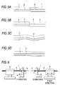
Publication No. Sho. 61-143704, etc.). Figs. 5A-5D are views
schematically showing the method for fusion splicing the optical
fibers. Reference numeral 1 denotes a glass fiber, 2 denotes
a core portion of optical fiber, and 3 denotes a micro bend.
Fig. 5A is a view showing a state where the core portions
2 of a pair of optical fibers 1 to be spliced are matched and
aligned with a predetermined end face spacing. In this state,
the discharge heating is performed to fuse the end portions
of optical fibers, and then the ends of optical fibers are butt
jointed together, as shown in Fig. 5B. When the core portions
2 are aligned and fusion spliced, the outer diameters of optical
fibers are not matched if the core portions are eccentric,
whereby the optical fibers are fused together in an offset state.
Usually, the additional discharge heating is performed to modify
this offset. By this additional discharge heating, the
self-alignment action occurs owing to a surface tension of glass,
so that the outer diameter portions of optical fibers are
modified to be smoothly continuous. It has been found that the
splice loss is improved by this additional discharge heating.
Fig. 5C is a view showing a state of optical fibers after
the additional discharge heating. As a result of the outer
diameters of optical fibers modified at the fused portion, a
micro bend 3 is produced in the core portion 2. This micro bend
3 increases the splice loss, whereby the optical fibers butt
jointed together at the time of fusion splicing are pulled back.
Fig. 5D is a view showing a state after pulling back the optical
fibers, in which the micro bend 3 in the core portion is stretched
into approximately linear form. Thereby, the splice loss can
be further improved.
In fusion splicing the submarine optical fiber cables,
to increase the splice strength of optical fiber, an fiber
coating portion of optical fiber at the time of fusion splicing
is clamped on a V-groove board (e.g., refer to Japanese Patent
Unexamined Publication No. Hei. 6-118251). Further, to reduce
a misalignment of the core portions of the optical fibers that
is likely to occur by cantilever support, it is required to
make the length (cleave length) of a glass fiber portion exposed
in the fusion spliced portion as short as possible.
Fig. 6 is a view showing the clamp method. In the same
figure, reference numeral 1 denotes a coated optical fiber,
4 denotes a glass fiber, 5 denotes a fiber coating, 6 denotes
an axial clamp, and 7 denotes a V-groove board clamp. The axial
clamp 6 clamps the coated optical fiber 1 and drives it in the
axial direction to adjust the end face distance, and butt and
pull back the optical fibers. The V-groove board clamp 7 is
in a free state relative to the axial movement of the coated
optical fiber 1, and holds the top end portion of the fiber
coating 5 that is located near the glass fiber 4 having the
coating removed. The V-groove board clamps 7 drive one glass
fiber 4 of one coated optical fiber 1 in the X-axis direction,
and the other glass fiber 4 of the other coated optical fiber
1 in the Y-axis direction to make alignment of the core portions
of the optical fibers.
The fusion splicing method of Figs. 5A-5D and the clamp
method of Fig. 6 as shown in the related art are the case where
the optical fiber outer diameters, the core portion diameters
and the fiber coating diameters are the same or substantially
same. In this case, the splice loss in fusion splicing has
typically a predetermined correlation between the estimated
loss and the actual measured loss. The estimated loss can be
obtained by measuring the misalignment of the core portion in
the splicing portion and the inclination of the core portion
in the splicing portion, and the splice loss is calculated from
this estimated loss.
However, when the optical fibers are fusion spliced, at
least one of optical fibers having a fiber coating of large
diameter, by the clamp method of Fig. 6, it has been found that
there is no correlation between the estimated loss and the actual
measured loss. For example, there is a case where an optical
fiber having and a glass fiber diameter of 125µm and a fiber
coating outer diameter of 0.4mm in which the effective core
cross section is expanded for use in the wavelength division
multiplexing transmission with the submarine optical fiber
cable, is fusion spliced with a dispersion shift fiber for
hermetic seal having a glass fiber diameter of 125µm, with
the surface coated with polyimide, and a fiber coating outer
diameter of 0.25mm, wherein each optical fiber is cleaved to
have the length of glass fiber of about 3mm. In this case,
comparing the estimated loss and the actual measured loss using
the clamp method in the above fusion splicing method, there
is no correlation and a fully random relationship.
This may be caused by a plurality of factors, including
a difference in the outer diameter between the optical fiber
coatings and a bending dependency of optical fiber, but its
detailed reason is not clear. Also, the splice loss is reduced
by performing the additional discharge heating and pull-back.
However, it has been found that there is no full correlation
between the estimated loss and the actual measured loss in the
related-art estimation method. However, in a submarine optical
fiber cable system, for example, the estimated loss is employed
in the case where the splice loss is practically difficult to
measure.
Summary of the Invention
The present invention has been achieved in the light of
the above-mentioned problems. It is an object of the invention
to provide a method for fusion splicing the optical fibers with
a low splice loss and a high strength in which the actual splice
loss can be estimated from the estimated loss in the case where
optical fibers with one fiber coating of a large diameter are
fusion spliced in short cleave length.
According to the present invention, there is provided
a method for fusion splicing the optical fibers, comprising;
aligning cores of the optical fibers to be spliced; fusing ends
of the optical fibers together with their respective cores in
alignment to splice; and measuring an inclination angle of the
fusion-spliced optical fibers with reference to the optical
fibers with their respective cores in alignment before fusing
to estimate a splice loss.
Brief Description of the Drawings
Figs. 1A and 1B are views showing a state where the optical
fibers are fusion spliced according to the present invention;
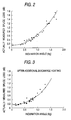
Fig. 2 is a graph representing the relationship between
fiber inclination angle and splice loss in a specific example
of the invention;
Fig. 3 is a graph representing the relationship between
fiber inclination angle and splice loss after additional
discharge in a specific example of the invention;
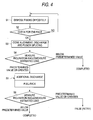
Fig. 4 is a flowchart showing a fusion splicing method
of the invention;
Figs. 5A-5D are views for explaining the related-art
fusion splicing forms; and
Fig. 6 is a view for explaining a clamp method for the
related-art fusion splicing.
Detailed Description of the Invention
The preferred embodiments of the present invention will
be described below with reference to the accompanying drawings.
Figs. 1A and 1B are views showing a state where the optical
fibers are fusion spliced. Fig. 1A is a state view of fusion
spliced optical fibers and Fig. 1B is an enlarged view of an
image pickup screen of the fusion spliced portion of optical
fibers. In Figs. 1A and 1B, reference numerals 11a an 11b denote
a coated optical fiber (hereinafter simply referred as an optical
fiber), 12a and 12b denote a glass fiber, 13a and 13b denote
a core portion, 14 denotes a fusion spliced portion, 15a and
15b denote a fiber coating. Further, 16a and 16b denote a V-groove
board, 17a and 17b denote a pressure clamp, and 18 denotes the
image pickup screen of the fusion spliced portion of optical
fibers.
The optical fiber 11a to the left includes the glass fiber
12a having a nominal outer diameter of 125 µm on which the coating
15a (UV resin) having an outer diameter of 0.4mm is applied.
The optical fiber 11b to the right includes the glass fiber
12b having a nominal outer diameter of 125 µm on which the coating
15b (UV resin) having an outer diameter of 0.25mm is applied.
The left and right optical fibers 11a and 11b are placed with
the end portions of fiber coatings 15a and 15b on the V- groove
boards 16a and 16b, and clamped by the pressure clamps 17a and
17b to be movable in the axial direction.
The optical fibers are fusion spliced by fusing the glass
fiber ends by discharge heating, and butt joining the fiber
ends together in the same manner as described in the prior art
and as shown in Figs. 5A-5D. Thereafter, the optical fibers
are subjected to additional discharge heating and pull-back,
as needed. At the fusion spliced portion 14, a micro bend occurs
due to butt joining the optical fibers together. This micro
bend is straightened to some extent by pulling back the optical
fibers after additional discharge heating.
The details of the fusion spliced portion 14 will be
described below through the image pickup screen 18 in which
an image is picked up by image observation means attached to
a fusion splicing apparatus. The optical glass fibers 12a and
12b has a misalignment d between the core portions 13a and 13b
at the fusion spliced ends, and a splicing angle offset f.
That is, d is an offset distance between the core axis of the
core portion 13a and the core axis of the core portion 13b,
and f is an angle of the top portion of the core portion 13a
with respect to the core axis of the core portion 13a . In related
art, the splice loss between the optical fibers of the same
kind is estimated by measuring the misalignment d and the
splicing angle offset f and calculating the estimated loss
"α=F(d,f)". This estimated loss α has a predetermined
correlation with the actual measured loss, and can be used for
the estimation of splice loss without any specific problems.
In this case, the estimated loss has a large percentage by the
misalignment d and a small percentage by the splicing angle
deviation f.
If the fiber coatings 15a and 15b for the optical fibers
11a and 11b to be spliced as shown in Fig. 1A have different
diameters, the estimated loss α calculated from the misalignment
d between the core portions 13a and 13b and the splicing angle
deviation f has no correlation with the actual measured loss
and can not be employed, as described in the related art. However,
in a case of the submarine optical fiber cable system, it is
often difficult to measure the splice loss, whereby the splice
loss is calculated by estimation.
The present invention has been achieved by noting that
the image of the glass fibers 12a and 12b before fusion splicing
is placed in a horizontal state and the image of the glass fibers
12a and 12b after fusion splicing is placed in an inclined state,
as viewed through the image pickup screen 18 for observing the
splicing portion 14 of optical fibers. That is, the present
invention has been achieved by noting a relative inclination
angle g of the glass fibers 12a and 12b after fusing splicing
with reference to the glass fibers 12a and 12b with their
respective core portions in alignment before fusion splicing.
As a result of various verifications, it was revealed that there
was a correlation between the inclination angle g of the glass
fibers 12a and 12b themselves on the image pickup screen and
the splice loss, rather than the splicing angle deviation f
between the core portions 13a and 13b, in the case where the
optical fibers of dissimilar diameters, with one fiber coating
having a larger diameter, are fusion spliced, as shown in Fig.
1A. In this embodiment as shown in Fig. 1A, the image observation
means is positioned so that the image of the glass fibers 12a
and 12b before fusion splicing is placed in a horizontal state
as viewed through the image pickup screen 18. However, the
position of the image observation means is not limited to this
embodiment. In the case where the image observation means is
positioned so that the image of the glass fibers 12a and 12b
is not placed in the horizontal state as viewed through the
image pickup screen 18, the inclination angle g of the glass
fibers 12a and 12b themselves before and after fusing splicing
is a relative inclination angle of the image of glass fibers
12a and 12b after fusion splicing with reference to the image
of glass fibers 12a and 12b before fusion splicing.
The image pickup screen 18 picks up an image of only a
vicinity of the fusion splicing portion 14 of optical fibers
to be fiber spliced, in which the image is displayed
substantially linearly in a form of representing a bent state
at the splicing portion of the spliced optical fibers. The
inclination angle g can be easily measured from the addresses
t1 and t2 at both ends of the image pickup screen.
In Fig. 1B, the inclination angle g is measured from
one image pickup screen 18. However, the inclination angle g
may be a vector synthesized angle of measured angles from
orthogonal two-axis directions perpendicular to the core axis
direction of the glass fibers using orthogonal two-axis
direction image observation means.
A specific example of the invention is presented below.
The optical fiber 11a to the left in Fig. 1A had a glass fiber
diameter of 125µm and an outer diameter of fiber coating of
0.4mm in which the effective core cross section was expanded
for use in the wavelength division multiplexing transmission
with the submarine optical fiber cable. The optical fiber 11b
to the right was a dispersion shift fiber for hermetic seal
having a glass fiber diameter of 125 µm, with the surface coated
with polyimide (coating thickness of 5µm), and an outer diameter
of fiber coating of 0.25mm.
The splicing ends of the optical fibers 11a and 11b were
cleaved so that the glass fibers 12a and 12b are exposed by
a length of 3mm from the fiber coatings 15a and 15b, respectively.
The optical fiber 11b when set in the fusion splicing apparatus,
had the polyimide coatings removed by a length of 1.5mm from
the top end by intermittent discharge employing a discharge
electrode of the apparatus, so that the glass fiber surface
was exposed.
The optical fibers 11a and 11b are fixed, using the clamp
method as shown in Fig. 6. That is, the fiber coatings 15a and
15b of the optical fibers are clamped and fixed by the axial
clamps 6, and clamped on the V-groove boards 7 so that the optical
fibers are made movable in the X direction. The adjustment of
spacing between glass fiber end faces is made by driving the
axial clamp 6. The alignment of the glass fiber end face is
made by driving one of the V-groove boards 7 in the X direction
(vertical direction in drawing) and the other in the Y direction
(forth and back direction in drawing).
Fig. 2 is a graph showing the relationship between the
inclination angle g (a vector synthesized angle of measured
angles from orthogonal two-axis directions) as shown in Fig.
1B and the actually measured splice loss by fusion splicing
the optical fibers using the clamp method. In Fig. 2, the
additional discharge heating and pull-back after fusion
splicing are not performed. On the contrary, Fig. 3 is a graph
showing the relationship between the inclination angle g and
the splice loss by performing the additional discharge heating
after actually measuring the inclination angle and the splice
loss of Fig. 2.
According to Figs. 2 and 3, it was found that there was
a correlation between the inclination angle g and the splice
loss actually measured. Further, it can be confirmed that the
splice loss is improved by performing the additional discharge
heating or the additional discharge heating and pull-back after
fusion splicing. From these results, the estimated loss α=F(g)
is calculated by measuring the inclination angle g and
formulating this as a variable, and can be employed as the splice
loss.
Table 1 shows the improved states of the splice loss by
the additional discharge heating and pull-back in fusion
splicing the optical fibers of dissimilar diameters in which
one fiber coating has a larger diameter.
| Number of samples 30 |
| | Splice loss (dB) | Yieldn (%) |
| | Average | Maximum | Minimum |
| Discharge heating | 0.64 | 1.71 | 0.13 | 43 |
| Additional discharge | 0.32 | 1.10 | 0.12 | 87 |
| Additional discharge + pull-back | 0.27 | 0.44 | 0.09 | 100 |
As will be apparent from Table 1, the splice loss is large
when fusion splicing the optical fibers by the discharge heating
alone, so that the yield is unexcellent. By performing the
additional discharge, the splice loss can be significantly
improved, and the yield can be improved almost twice better
than that when no additional discharge is performed. By
performing the pull-back besides the additional discharge
heating, the splice loss can be further improved, especially
when the optical fibers having the large splice loss are spliced,
and the yield can be made at about 100%.
Referring to a flowchart of Fig. 4, the fusion splicing
method of the invention will be described below. First of all,
at step S1, the optical fibers are set on the fusion splicing
apparatus and have the glass fiber ends disposed oppositely
by the well-known method as shown in Fig. 6. Then, at step S2,
the end face of glass fiber is checked to determine whether
or not there is the dust and the cleave condition is excellent.
If the answer is NO, the check is retried, or otherwise the
procedure goes to step S3.
At step S3, the discharge heating is performed under the
predetermined fusion splicing conditions, the glass fiber ends
are butt jointed together. At step S4, the inclination angle
of glass fiber is measured, and the estimated loss is calculated
based on this inclination angle. If this estimated loss is below
a predetermined value, the fusion splicing is ended. On the
contrary, if the estimated loss is greater than or equal to
the predetermined value, the procedure goes to step S5. At step
S5, the additional discharge heating or the additional discharge
heating and pull-back are performed. Thereafter, at step S6,
the inclination angle is measured again, in which if the
estimated loss is below a predetermined value, the procedure
is ended, or otherwise the splicing is false, whereby the
procedure returns to the initial state and retried.
The present invention is not limited to the above
embodiments, but may be applied to, besides the optical fibers
having the coating of equal diameter and a combination of optical
fibers having the outer diameters of 0.4mm and 0.25mm, the
optical fibers having the dependency between the inclination
angle of glass fiber and the splice loss.
As will be apparent from the above description, with the
present invention, the splice loss in fusion splicing the optical
fibers, at least one fiber coating having a larger diameter,
can be obtained by measuring an inclination angle of the glass
fibers in the optical fibers and calculating the estimated loss.
Further, if the estimated loss is greater than or equal to a
predetermined value, the additional discharge heating and the
pull-back are automatically performed, whereby the splice loss
can be improved. Moreover, the degraded splicing strength is
avoided because the optical fibers are spliced by clamping the
coatings.