EP1384973A2 - Interferometric system for the simultaneous measurement of the index of refraction and of the thickness of transparent materials, and related procedure - Google Patents
Interferometric system for the simultaneous measurement of the index of refraction and of the thickness of transparent materials, and related procedure Download PDFInfo
- Publication number
- EP1384973A2 EP1384973A2 EP03425482A EP03425482A EP1384973A2 EP 1384973 A2 EP1384973 A2 EP 1384973A2 EP 03425482 A EP03425482 A EP 03425482A EP 03425482 A EP03425482 A EP 03425482A EP 1384973 A2 EP1384973 A2 EP 1384973A2
- Authority
- EP
- European Patent Office
- Prior art keywords
- refraction
- index
- thickness
- sample
- measurement
- Prior art date
- Legal status (The legal status is an assumption and is not a legal conclusion. Google has not performed a legal analysis and makes no representation as to the accuracy of the status listed.)
- Withdrawn
Links
Images



Classifications
-
- G—PHYSICS
- G01—MEASURING; TESTING
- G01N—INVESTIGATING OR ANALYSING MATERIALS BY DETERMINING THEIR CHEMICAL OR PHYSICAL PROPERTIES
- G01N21/00—Investigating or analysing materials by the use of optical means, i.e. using sub-millimetre waves, infrared, visible or ultraviolet light
- G01N21/17—Systems in which incident light is modified in accordance with the properties of the material investigated
- G01N21/41—Refractivity; Phase-affecting properties, e.g. optical path length
- G01N21/45—Refractivity; Phase-affecting properties, e.g. optical path length using interferometric methods; using Schlieren methods
-
- G—PHYSICS
- G01—MEASURING; TESTING
- G01B—MEASURING LENGTH, THICKNESS OR SIMILAR LINEAR DIMENSIONS; MEASURING ANGLES; MEASURING AREAS; MEASURING IRREGULARITIES OF SURFACES OR CONTOURS
- G01B11/00—Measuring arrangements characterised by the use of optical techniques
- G01B11/02—Measuring arrangements characterised by the use of optical techniques for measuring length, width or thickness
- G01B11/06—Measuring arrangements characterised by the use of optical techniques for measuring length, width or thickness for measuring thickness ; e.g. of sheet material
- G01B11/0616—Measuring arrangements characterised by the use of optical techniques for measuring length, width or thickness for measuring thickness ; e.g. of sheet material of coating
- G01B11/0675—Measuring arrangements characterised by the use of optical techniques for measuring length, width or thickness for measuring thickness ; e.g. of sheet material of coating using interferometry
-
- G—PHYSICS
- G01—MEASURING; TESTING
- G01N—INVESTIGATING OR ANALYSING MATERIALS BY DETERMINING THEIR CHEMICAL OR PHYSICAL PROPERTIES
- G01N21/00—Investigating or analysing materials by the use of optical means, i.e. using sub-millimetre waves, infrared, visible or ultraviolet light
- G01N21/17—Systems in which incident light is modified in accordance with the properties of the material investigated
- G01N21/41—Refractivity; Phase-affecting properties, e.g. optical path length
- G01N2021/4126—Index of thin films
Definitions
- the present invention refers to a system, and related procedure, for the simultaneous determination of both the index of refraction and the thickness of transparent materials, including liquids.
- the most significant aspect of the invention is that a single measurement system is employed, based on a shear interferometric type of interferometric technique, with the further possibility of varying the wavelength of the laser source used.
- the evaluation of the index of refraction and of the thickness of the investigated material occurs in two steps: In the first step the variation of the "optical path" due to the variation of the wavelength of the laser source used is determined (by “optical path” is intended the product between the index of refraction and the thickness of the material analyzed); in the second step instead, the index of refraction of the material is determined, using the value of the previously identified optical path and on the basis of known phase reconstruction techniques, such as, for example, the method based on the Fourier transform. From the so calculated index of refraction and from the value of the optical path the value of the thickness of the investigated material is obtained.
- the invention falls in particular, but not exclusively, in the technical field of optical characterization of materials and in the field of application of optical instrumentation manufacture.
- the methods developed for the simultaneous measurement of the index of refraction and of the thickness are manifold.
- the invention which is the object of this patent application, represents a significant improvement with respect to other systems of measurement of the index of refraction and of thickness.
- scope of the inventors is to develop a system able to determine simultaneously both the index of refraction and the thickness of transparent materials by means of "a single measurement operation", providing a high measurement precision.
- the submitted invention is thus a measurement system where a "shear interferometric" type of interferometry is employed, with the additional advantage of varying the wavelength of the luminous radiation.
- the system at present preferred by the inventors for performing the measurement, is described hereinafter in its essential elements:
- the emitted wavelength of the coherent and monochromatic light source must be easily tuned and controlled.
- the best way to realize this invention is to use a system where the sample is in rotation with respect to a coherent and monochromatic light beam, which emitted wavelength can be tuned.
- Said system has particular simplicity of use, versatility and compactness characteristics.
- the system can have configurations different from those described in the present invention and can be developed with a different number and type of optical components without prejudicing or changing the system forming the object of the present invention.
- Fig. 1 we can see that the system composed of a laser diode DFB 1, the laser beam, in output an optical fiber 3, is collimated through collimator 4. Along the direction of propagation of laser beam 13 is placed the sample to be measured 5. Laser radiation 13, after traversing sample 5, impinges upon photodiode 9. Through oscilloscope 10 it is possible to acquire the interferometric signal on a personal computer 11 for subsequent analyses. The sample is placed on a precision rotating stage 7. By means of personal computer 11, bus IEEE-488 12 and supply 2 it is possible to control the wavelength of the laser radiation emitted by source 1.
- the wavelength of laser source 1 is fixed, if the sample to be measured 5 is caused to rotate by means of rotating base 7, there is a variation of optical path between the rays that propagate inside sample 5.
- the optical path is expressed as the product of geometric path d by index of refraction n.
- the optical path variation depends on angle of incidence 8 and this produces interferometric signal 14.
- bus IEEE-488 12 and supply 2 it is possible to vary the wavelength of laser source 1 and then, for each fixed angle of incidence 8, to vary the phase of interferometric signal 14.
- Fig. 2 shows a view from above of the sample to be measured
- the difference of optical path between the various rays 15, 20, 16, 17 which propagate inside the sample, is due only to the reflections and refractions undergone by said rays on surfaces 18 and 19 of the sample.
- the optical path difference depends on angle of incidence 8 and on said difference will depend the acquired interferometric signal.
- ray 13 is subject to a refraction at air-sample surface 18, propagates within the sample (ray 15) and part of it is subject to a refraction at sample-air interface 19 (ray 21) and part is reflected by sample-air interface surface 19 (ray 20).
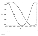
- the interferometric signal can be determined by the following equation: where ⁇ is the wavelength of the laser used; I 0 is linked to the intensity of the interfering beams , and ⁇ depends on the coherence of the luminous source.
- Case (a) refers to a silicon sample
- case (b) refers to a lithium niobate sample.
- Fig. 5 the interferometric signal according to the angle of incidence and for a fixed wavelength.
- the signal is thus described by equation 1, with ⁇ fixed.
- the invented system offers the possibility of determining from the same family of acquired interferometric signals both the index of refraction and the thickness by means of two distinct phases, so as to improve the accuracy with which the two entities are determined.
Landscapes
- Physics & Mathematics (AREA)
- General Physics & Mathematics (AREA)
- General Health & Medical Sciences (AREA)
- Chemical & Material Sciences (AREA)
- Analytical Chemistry (AREA)
- Biochemistry (AREA)
- Life Sciences & Earth Sciences (AREA)
- Health & Medical Sciences (AREA)
- Immunology (AREA)
- Pathology (AREA)
- Length Measuring Devices By Optical Means (AREA)
- Investigating Or Analysing Materials By Optical Means (AREA)
- Instruments For Measurement Of Length By Optical Means (AREA)
Abstract
Description
- Provide an holder that serves to house the material whose index of refraction and thickness are to be measured;
- said holder is placed on a precision rotating stage and then duly inserted in the measurement system so that a coherent and monochromatic light beam, is transmitted through the sample to be measured;
- the coherent light going through the sample is subject to various reflections and refractions at the sample interfaces, thereby producing an interference signal;
- from observation of the phase variation of the interference signal, obtained by tuning of the wavelength of the coherent light, the optical path is obtained;
- from said optical path, and observing the interference signal, obtained for each fixed wavelength of the coherent light source, the index of refraction of the material is obtained;
- from said index of refraction value and from the optical path value the thickness of the sample to be measured is obtained.
- 1
- laser diode
- 2
- laser diode supply
- 3
- optical fiber
- 4
- collimator
- 5
- sample to be measured
- 6
- sample holder
- 7
- precision rotating stage
- 8
- angle of incidence
- 9
- photodiode
- 10
- oscilloscope
- 11
- personal computer
- 12
- Bus IEEE-488


Claims (12)
- System for the measurement of the index of refraction and the thickness of transparent materials, made up of a "shear interferometer" type, characterized by the fact to be, in turn, made up of: a laser source (1), a supply (2), a collimator (4), a precision rotating stage (7), a photodiode (9), an oscilloscope (10), a control bus IEEE-488 (12), and a personal computer (11).
- System for the measurement of the index of refraction and the thickness of transparent materials, according to Claim 1, characterized by the fact that the laser source (1) is such as to vary the emission wavelength, for example, through the supply (2), controlled through bus IEEE-488 (12) by a personal computer (11).
- System for the measurement of the index of refraction and the thickness of transparent materials, according to Claim 1, characterized by the fact that the acquisition system can be chosen optionally, i.e. a photodiode (9) interfaced with an oscilloscope (10) controlled, through bus IEEE-488 (12), by a personal computer (11).
- System for the measurement of the index of refraction and the thickness of transparent materials, characterized by the fact that the sample (5) is formed by homogeneous material of plane and parallel faces.
- System for the measurement of the index of refraction and the thickness of transparent materials, according to Claim 4, characterized by the fact that the sample (5) is placed vertically on a support (6) and rests on a precision rotating stage (7), whose position is on the direction of the laser beam (13).
- System for the measurement of the index of refraction and the thickness of transparent materials, according to Claims 1, 4 and 5, characterized by the fact that the laser radiation (13) which traverses the sample is subject to various reflections and refractions within the sample (5) which, by interfering with each other, produce the interferometric signal (14).
- System for the measurement of the index of refraction and the thickness of transparent materials, according to the previous claims, characterized by the fact that to perform the measurement of the index of refraction and the thickness of the analyzed sample (5), it is necessary to determine first the measurement of the optical path and subsequently the index of refraction of the sample (5); from these two values the thickness of the investigated sample (5) is evaluated.
- System for the measurement of the index of refraction and the thickness of transparent materials, according to Claim 7, characterized by the fact that the measurement of the optical path occurs by evaluating the interferometric signal obtained upon varying of the angle of incidence (8) for each fixed wavelength of the laser source (1); from the symmetry of the signal acquired on the personal computer (11) it is possible to determine the normal incidence condition ( = 0°); from the interferometric signal relating to said position it is possible to acquire the optical path inside the sample (5).
- System for the measurement of the index of refraction and the thickness of transparent materials, according to Claim 8, characterized by the fact that, by analyzing the interferometric signal according to the angle of incidence (8) and for a fixed wavelength, and using the value of the previously evaluated optical path, it is possible to acquire the value of the index of refraction of the analyzed sample (5).
- System for the measurement of the index of refraction and the thickness of transparent materials, according to Claim 9, characterized by the fact that, by using the value of the optical path and of the index of refraction it is possible to acquire the thickness of the analyzed sample (5).
- Procedure to measure the index of refraction and the thickness of transparent materials, according to all the previous Claims, to be performed as follows:provide a support that serves to house the material whose index of refraction and the thickness are to be measured;said support is placed on a precision rotating stage and then duly inserted in the measurement system so that the sample to be measured is traversed by a coherent and monochromatic light beam;the coherent light that traverses the sample is subject to various reflections and refractions at the sample interfaces, producing an interference signal;from observation of the phase variation of the interference signal, following the variation of the wavelength of the coherent light, the optical path is obtained;from said optical path and observing the interference signal, obtained for each fixed wavelength of the coherent light source, the index of refraction of the material is obtained;from said index of refraction value and from the optical path value the thickness of the sample to be measured is obtained.
- System, and related procedure, for measurement of the index of refraction and the thickness of transparent materials, characterized by the fact that it can be used also for liquids.
Applications Claiming Priority (2)
| Application Number | Priority Date | Filing Date | Title |
|---|---|---|---|
| ITRM20020397 | 2002-07-24 | ||
| IT2002RM000397A ITRM20020397A1 (en) | 2002-07-24 | 2002-07-24 | INTERPHEROMETRIC SYSTEM FOR SIMULTANEOUS MEASUREMENT OF THE REFRACTION INDEX AND THICKNESS OF TRANSPARENT MATERIALS AND RELATED PROCEDIMENT |
Publications (2)
| Publication Number | Publication Date |
|---|---|
| EP1384973A2 true EP1384973A2 (en) | 2004-01-28 |
| EP1384973A3 EP1384973A3 (en) | 2005-11-30 |
Family
ID=11456424
Family Applications (1)
| Application Number | Title | Priority Date | Filing Date |
|---|---|---|---|
| EP03425482A Withdrawn EP1384973A3 (en) | 2002-07-24 | 2003-07-18 | Interferometric system for the simultaneous measurement of the index of refraction and of the thickness of transparent materials, and related procedure |
Country Status (3)
| Country | Link |
|---|---|
| US (1) | US7046373B2 (en) |
| EP (1) | EP1384973A3 (en) |
| IT (1) | ITRM20020397A1 (en) |
Families Citing this family (5)
| Publication number | Priority date | Publication date | Assignee | Title |
|---|---|---|---|---|
| DE102010006237A1 (en) * | 2010-01-26 | 2011-07-28 | Siemens Aktiengesellschaft, 80333 | Method and device for measuring the thickness of a layer |
| US8982355B2 (en) * | 2010-12-09 | 2015-03-17 | The United States Of America As Represented By The Administrator Of The National Aeronautics And Space Administration | Smart optical material characterization system and method |
| US20150253127A1 (en) * | 2014-03-04 | 2015-09-10 | Honeywell Asca Inc. | Thickness Determination of Web Product by Mid-infrared Wavelength Scanning Interferometry |
| TWI819008B (en) * | 2018-06-21 | 2023-10-21 | 以色列商魯姆斯有限公司 | Measurement technique for refractive index inhomogeneity between plates of a lightguide optical element (loe) |
| WO2025029666A1 (en) * | 2023-07-28 | 2025-02-06 | The Trustees Of Princeton University | Methods and systems for dynamic z-scanning, and single-lens addition to microscopy |
Family Cites Families (5)
| Publication number | Priority date | Publication date | Assignee | Title |
|---|---|---|---|---|
| US4891526A (en) * | 1986-12-29 | 1990-01-02 | Hughes Aircraft Company | X-Y-θ-Z positioning stage |
| JPS6475903A (en) * | 1987-09-18 | 1989-03-22 | Ricoh Kk | Method for measuring refractive index and film thickness |
| US5151752A (en) * | 1988-06-16 | 1992-09-29 | Asahi Kogaku Kogyo K.K. | Method of measuring refractive indices of lens and sample liquid |
| JPH0781818B2 (en) * | 1991-12-11 | 1995-09-06 | 工業技術院長 | Shearing interferometer for measuring lens lateral aberration |
| US6496268B1 (en) * | 2000-07-18 | 2002-12-17 | Innovative Technology Licensing, Llc | Laser-based glass thickness measurement system and method |
-
2002
- 2002-07-24 IT IT2002RM000397A patent/ITRM20020397A1/en unknown
-
2003
- 2003-07-18 EP EP03425482A patent/EP1384973A3/en not_active Withdrawn
- 2003-07-22 US US10/624,189 patent/US7046373B2/en not_active Expired - Fee Related
Also Published As
| Publication number | Publication date |
|---|---|
| EP1384973A3 (en) | 2005-11-30 |
| US7046373B2 (en) | 2006-05-16 |
| ITRM20020397A0 (en) | 2002-07-24 |
| US20050036154A1 (en) | 2005-02-17 |
| ITRM20020397A1 (en) | 2004-01-26 |
Similar Documents
| Publication | Publication Date | Title |
|---|---|---|
| US6856384B1 (en) | Optical metrology system with combined interferometer and ellipsometer | |
| US6469788B2 (en) | Coherent gradient sensing ellipsometer | |
| US7741598B2 (en) | Optical interrogation system and method for using same | |
| US5151752A (en) | Method of measuring refractive indices of lens and sample liquid | |
| US11169027B2 (en) | Interferometer systems and methods thereof | |
| KR20130018553A (en) | Film thickness measurement apparatus | |
| GB2248497A (en) | An optical sensor | |
| JP3699810B2 (en) | Method and apparatus for measuring refractive index distribution | |
| US9915564B1 (en) | Inspecting a slab of material | |
| JP2010525316A (en) | Method and apparatus for measuring the refractive index of a material with a Bragg grating | |
| US8953168B2 (en) | Optical sensing devices and methods for detecting samples using the same | |
| US7046373B2 (en) | Interferometric system for the simultaneous measurement of the index of refraction and of the thickness of transparent materials, and related procedure | |
| JP2005106835A (en) | Method and apparatus for measuring refractive index distribution | |
| WO2017067542A1 (en) | Measuring device and method for measuring the thickness of a flat sample | |
| KR20150075355A (en) | Refractive index distribution measuring method, refractive index distribution measuring apparatus, and method for manufacturing optical element | |
| US6449049B1 (en) | Profiling of aspheric surfaces using liquid crystal compensatory interferometry | |
| US20060126067A1 (en) | Crystal grating apparatus | |
| RU2769885C1 (en) | Device for deformation measuring | |
| US5659393A (en) | Method of and device for measuring the refractive index of wafers of vitreous material | |
| RU2039969C1 (en) | Holographic method of measuring refractivities of liquid and gaseous media | |
| Andrushchak et al. | A new method for refractive index measurement of isotropic and anisotropic materials in millimeter and submillimeter wave range | |
| Brown et al. | Predictions of stray light modeling on the ultimate performance of acousto-optic processors | |
| Saaskilahti et al. | Interferometric investigation of SAW devices | |
| JP2652667B2 (en) | Refractive index measurement method | |
| Sümer et al. | Investigating the experimental limits of the Brewster's angle method |
Legal Events
| Date | Code | Title | Description |
|---|---|---|---|
| PUAI | Public reference made under article 153(3) epc to a published international application that has entered the european phase |
Free format text: ORIGINAL CODE: 0009012 |
|
| AK | Designated contracting states |
Kind code of ref document: A2 Designated state(s): AT BE BG CH CY CZ DE DK EE ES FI FR GB GR HU IE IT LI LU MC NL PT RO SE SI SK TR |
|
| AX | Request for extension of the european patent |
Extension state: AL LT LV MK |
|
| PUAL | Search report despatched |
Free format text: ORIGINAL CODE: 0009013 |
|
| AK | Designated contracting states |
Kind code of ref document: A3 Designated state(s): AT BE BG CH CY CZ DE DK EE ES FI FR GB GR HU IE IT LI LU MC NL PT RO SE SI SK TR |
|
| AX | Request for extension of the european patent |
Extension state: AL LT LV MK |
|
| 17P | Request for examination filed |
Effective date: 20060328 |
|
| AKX | Designation fees paid |
Designated state(s): AT BE BG CH CY CZ DE DK EE ES FI FR GB GR HU IE IT LI LU MC NL PT RO SE SI SK TR |
|
| 17Q | First examination report despatched |
Effective date: 20071122 |
|
| STAA | Information on the status of an ep patent application or granted ep patent |
Free format text: STATUS: THE APPLICATION IS DEEMED TO BE WITHDRAWN |
|
| 18D | Application deemed to be withdrawn |
Effective date: 20080603 |