EP1384952A2 - Smoke guiding apparatus of wall-mounted microwave oven - Google Patents
Smoke guiding apparatus of wall-mounted microwave oven Download PDFInfo
- Publication number
- EP1384952A2 EP1384952A2 EP03250003A EP03250003A EP1384952A2 EP 1384952 A2 EP1384952 A2 EP 1384952A2 EP 03250003 A EP03250003 A EP 03250003A EP 03250003 A EP03250003 A EP 03250003A EP 1384952 A2 EP1384952 A2 EP 1384952A2
- Authority
- EP
- European Patent Office
- Prior art keywords
- guide plate
- power
- feed motor
- response
- guide
- Prior art date
- Legal status (The legal status is an assumption and is not a legal conclusion. Google has not performed a legal analysis and makes no representation as to the accuracy of the status listed.)
- Ceased
Links
Images


Classifications
-
- F—MECHANICAL ENGINEERING; LIGHTING; HEATING; WEAPONS; BLASTING
- F24—HEATING; RANGES; VENTILATING
- F24C—DOMESTIC STOVES OR RANGES ; DETAILS OF DOMESTIC STOVES OR RANGES, OF GENERAL APPLICATION
- F24C15/00—Details
- F24C15/20—Removing cooking fumes
- F24C15/2078—Removing cooking fumes movable
- F24C15/2092—Removing cooking fumes movable extendable or pivotable
-
- H—ELECTRICITY
- H05—ELECTRIC TECHNIQUES NOT OTHERWISE PROVIDED FOR
- H05B—ELECTRIC HEATING; ELECTRIC LIGHT SOURCES NOT OTHERWISE PROVIDED FOR; CIRCUIT ARRANGEMENTS FOR ELECTRIC LIGHT SOURCES, IN GENERAL
- H05B6/00—Heating by electric, magnetic or electromagnetic fields
- H05B6/64—Heating using microwaves
- H05B6/642—Cooling of the microwave components and related air circulation systems
- H05B6/6423—Cooling of the microwave components and related air circulation systems wherein the microwave oven air circulation system is also used as air extracting hood
Definitions
- the present invention relates to wall-mounted microwave ovens, and more particularly to a smoke guiding apparatus of a wall-mounted microwave oven, which guides smoke generated therebelow to an exhaust path of the microwave oven.
- a wall-mounted microwave oven is installed on a wall surface, above an oven range, and functions as a hood to suck steam and smoke generated from food cooked therebelow, and discharge them to the outside of a cooking area.
- Figure 1 shows the construction of a smoke guiding apparatus of a conventional wall-mounted microwave oven.
- a body 1 of the wall-mounted microwave oven includes a cooking chamber (not shown) to cook food therein and a machine room (not shown) which stores various machine parts.
- the cooking chamber and the machine room are partitioned from one another.
- the body 1 of the microwave oven further includes an exhaust fan 3 which is installed in an upper portion of a back of the body 1 so as to exhaust gas or smoke generated from an oven range 2, which is positioned below the body 1.
- An exhaust inlet (not shown) is formed in a lower portion of the body 1 so as to suck the gas or smoke where the exhaust fan 3 is operated.
- An exhaust path 4 is formed within the body 1 to guide the gas or smoke sucked into the exhaust inlet to the exhaust fan 3.
- a smoke guiding apparatus 5 is installed beneath the body 1 so as to guide the smoke therebelow to the exhaust inlet.
- the smoke guiding apparatus 5 comprises a limit switch 8, a feed motor 9 and a microcomputer 10.
- the limit switch 8 is provided to be turned on or off according to a moving position of a guide plate 7.
- the guide plate 7 is inserted into a guide groove of a guide member 6 to move straight forward and backward.
- the feed motor 9 moves the guide plate 7 by rotating forwardly or reversely in response to a control signal output from the microcomputer 10.
- the microcomputer 10 controls forward/reverse rotation of the feed motor 9, or stops the rotation of the feed motor 9 in response to an output signal of the limit switch 8.
- a gear shaft of the feed motor 9 a pinion gear 12 engages with a rack gear 11 formed beneath the guide plate 7, thus enabling the guide plate 7 to move forward and backward according to the rotation of the feed motor 9.
- two grooves are formed in the guide plate 7 in a progress direction of the guide plate 7.
- the limit switch 8 is constructed to output different output signals according to positions of a moving surface and the two grooves of the guide plate 7.
- the microcomputer 10 reads an output signal of the limit switch 8, and controls the feed motor 9 based upon the output signal, thus allowing the guide plate 7 to move to a guide position or an initial position (original position) of the guide plate 7.
- the conventional smoke guiding apparatus 5 is problematic in that it increases the entire manufacturing cost thereof by employing the microcomputer 10. Further, it cannot be applied to mechanical microwave ovens which do not employ a microcomputer.
- an aim of the present invention is to provide a driving circuit to control a smoke guiding apparatus of a microwave oven, which is simple and effective. Ideally, it is desired to provide a driving circuit that does not employ a microprocessor.
- a controller for a smoke guiding apparatus of a wall-mounted microwave oven having an exhaust motor which discharges smoke therebelow to the outside of the wall-mounted microwave oven, a guide plate which guides the smoke, and a feed motor which moves the guide plate between an initial position and a guide position of the guide plate
- the controller comprising a switching unit which supplies power to the feed motor so as to move the guide plate between the guide position and the initial position in conjunction with an operation of the exhaust motor, a first limit switch which shuts off the power supplied to the feed motor in response to the guide plate reaching the guide position, and a second limit switch which shuts off the power supplied to the feed motor in response to the guide plate reaching the initial position.
- a controller for a smoke guiding apparatus of a wall-mounted microwave oven having an exhaust motor which discharges smoke therebelow to the outside of the wall-mounted microwave oven, a guide plate which guides the smoke, and a feed motor which receives DC power and moves the guide plate between an initial position and a guide position of the guide plate
- the controller comprising a switching unit which supplies the DC power to the feed motor so as to move the guide plate between the guide position and the initial position in conjunction with an operation of the exhaust motor, a first limit switch which shuts off the DC power supplied to the feed motor in response to the guide plate reaching the guide position, and a second limit switch which shuts off the DC power supplied to the feed motor in response to the guide plate reaching the initial position.
- a smoke guiding apparatus of a wall-mounted microwave oven having an exhaust motor which discharges smoke therebelow to the outside of the wall-mounted microwave oven, and a guide plate which guides the smoke
- the smoke guiding apparatus comprising a feed motor which receives AC power and moves the guide plate to an initial position or a guide position of the guide plate, a switching unit which supplies the AC power to the feed motor so as to move the guide plate to the guide position in response to the exhaust motor being operated, and supplies the AC power to the feed motor so as to move the guide plate to the initial position in response to the operation of the exhaust motor being stopped, a first limit switch which shuts off the AC power supplied to the feed motor in response to the guide plate reaching the guide position, and a second limit switch which shuts off the AC power supplied to the feed motor in response to the guide plate reaching the initial position.
- FIG. 2 shows the construction of a smoke guiding apparatus of a wall-mounted microwave oven according to the present invention.
- the smoke guiding apparatus includes guide members 20 having corresponding guide grooves 22.
- the guide grooves 22 are formed in a longitudinal direction to allow a guide plate 21 to slide forward and backward.
- two holes 23 are formed beside the respective guide groove 22.
- First and second limit switches 24 and 25, which respectively sense an initial position and a guide position of the guide plate 21 are installed so as to have their terminals inwardly project through the corresponding holes 23.
- the first limit switch 24 is a normal open-type switch which is turned on in response to its terminal being pressed, and is turned off in response to its terminal not being pressed.
- the second limit switch 25 is a normal close-type switch which is turned off in response to its terminal being pressed, and is turned on in response to its terminal not being pressed.
- a sensing groove 26 is formed on a side of the guide plate 21 which comes into contact with the guide member 20 having the holes 23. Accordingly, the terminal of the first limit switch 24 is projected and inserted into the sensing groove 26 where the guide plate 21 reaches the guide position, thus allowing the first limit switch 24 to be turned off. Where the guide plate 21 presses the terminal of the second limit switch 25 at the initial position, the second limit switch 25 is turned off. Where the guide plate 21 moves to the guide position from the initial position, the terminal of the second limit switch 25 is projected to its normal position, thus enabling the second limit switch 25 to be turned on.
- a rack gear 27 is formed beneath the guide plate 21.
- the rack gear 27 engages with a pinion gear 30 connected to a driving shaft 29 of the feed motor 28 to move the guide plate 21 to the guide position or the initial position, according to a rotating direction of the driving shaft 29.
- Figure 3 shows a circuit diagram of a driving circuit of a smoke guiding apparatus having a DC feed motor in a wall-mounted microwave oven according to an embodiment of the present invention.
- thermostat T.C.O which is turned on in response to a temperature of smoke generated therebelow, i.e., while food is cooked by an oven range, being equal to or greater than a predetermined temperature, is connected to an external alternating current (AC) power source 100.
- the other end of the thermostat T.C.O is connected to an exhaust motor VM.
- the exhaust motor VM receives the external AC power in response to the thermostat T.C.O being turned on, and causes the smoke to be sucked into an exhaust path of the microwave oven, so as to discharge the smoke to the outside of the microwave oven.
- the exhaust motor VM is connected in parallel with a relay coil R.
- the relay coil R receives the external AC power in response to the thermostat T.C.O being turned on, and turns corresponding relay switches Ra1, Rb1, Ra2 and Rb2 on or off.
- a low voltage transformer LVT which decreases an external AC voltage level to a predetermined voltage level, is connected to lines branched from both ends of the external AC power source 100.
- a rectifying unit 200 which converts the AC power into DC power, is connected to both ends of the low voltage transformer LVT.
- the relay switch Rb1 that is, a first relay contact B switch Rb1 is disposed between one end of the rectifying unit 200 and a positive (+) input terminal of the feed motor M.
- the first relay switch Rb1 is turned on in a normal condition and switched to a turned-off state in response to power being supplied to the relay coil R.
- the relay switch Ra1 that is, a first relay contact A switch Ra1 is disposed between one end of the rectifying unit and a negative (-) input terminal of the feed motor M.
- the first relay switch Ra1 is turned off in a normal condition and switched to a turned-on state in response to the power being supplied to the relay coil R.
- the relay switch Ra2 that is, a second relay contact A switch Ra2 is branched from the first relay switch Rb1 and the positive (+) input terminal of the feed motor M, connected in series with a first limit switch FRONT SW, which senses a guide position of the guide plate 21, and connected to the other end of the rectifying unit 200.
- the relay switch Rb2 that is, a second relay contact B switch Rb2, is branched from the first relay switch Ra1 and the negative (-) input terminal of the feed motor M, connected in series with a second limit switch REAR SW, which senses an initial position of the guide plate 21, and connected to the other end of the rectifying unit 200.
- the thermostat T.C.O is turned on. Accordingly, the external AC power 100 is supplied to the exhaust motor VM and the relay coil R, and the exhaust motor VM is operated to cause the smoke to be sucked into the exhaust path and discharged to the outside of the microwave oven.
- the first relay switch Rb1 and the second relay switch Rb2 are switched to respective turned-off states from turned-on states.
- the first relay contact A switch Ra1 and the second relay contact A switch Ra2 are switched to respective turned-on states from turned-off states.
- the DC power, the first relay switch Ra1, the feed motor M, the second relay switch Ra2 and the first limit switch FRONT SW form a loop. Accordingly, the feed motor M is forwardly rotated, thus enabling the guide plate 21 to move to the guide position from the initial position. In this case, the second limit switch REAR SW is switched to a turned-on state from a turned-off state according to the movement of the guide plate 21.
- the guide plate 21 reaches the guide position by the forward rotation of the feed motor M, the terminal of the first limit switch FRONT SW is projected and inserted into the sensing groove 26 formed in the guide plate 21. As such, the first limit switch FRONT SW is turned off. Accordingly, the supply of power to the feed motor M is shut off and the guide plate 21 is then stopped, thus enabling the guide plate 21 to guide the smoke into the exhaust path at the guide position, so as to prevent the smoke from flowing into a cooking space.
- the temperature of the smoke decreases.
- the thermostat T.C.O is turned off, thus shutting off the external AC power supplied to the exhaust motor VM and the relay coil R.
- the first relay switch Rb1 and the second relay switch Rb2 are returned to the respective turned-on states from the turned-off states, while the first relay contact A switch Ra1 and the second relay contact A switch Ra2 are returned to the respective turned-off states from the turned-on states.
- the second limit switch REAR SW is turned on, so the DC power, the first relay contact B switch Rb1, the feed motor M, the second relay contact B switch Rb2 and the second limit switch REAR SW form a loop. Accordingly, the feed motor M is reversely rotated, thus enabling the guide plate 21 to move to the initial position from the guide position. In this case, the first limit switch FRONT SW is turned on again.
- the guide plate 21 reaches the initial position by the reverse rotation of the feed motor M, the terminal of the second limit switch REAR SW is pressed by the guide plate 21. As such, the second limit switch REAR SW is turned off, and the supply of power to the feed motor M is shut off, thus stopping the movement of the guide plate 21. Accordingly, the guide plate 21 is returned to the original position and a smoke guidance operation is no longer performed.
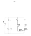
- FIG. 4 shows a circuit diagram of a driving circuit of a smoke guiding apparatus having an AC feed motor in a wall-mounted microwave oven according to another embodiment of the present invention.
- a thermostat T.C.O which is turned on in response to a temperature of smoke generated therebelow, i.e., while food is cooked by an oven range, being equal to or greater than a predetermined temperature, is connected to an external AC power source 100.
- the other end of the thermostat T.C.O is connected to an exhaust motor VM.
- the exhaust motor VM receives the external AC power in response to the thermostat T.C.O being turned on, and causes the smoke to be sucked into an exhaust path of the microwave, so as to discharge the smoke to the outside of the microwave oven.
- the exhaust motor VM is connected in parallel with a relay coil R.
- the relay coil R receives the external AC power in response to the thermostat T.C.O being turned on, and turns corresponding relay switches Ra and Rb on or off.
- the relay switch Ra and a first limit switch FRONT SW are disposed between one end of the external AC power source 100 and an input terminal, i.e., for a forward rotation, of the feed motor M.
- the relay switch Ra is turned off in a normal condition and switched to a turned-on state in response to power being supplied to the relay coil R.
- the first limit switch FRONT SW is connected in series with the relay switch Ra and senses the guide position of the guide plate 21.
- the relay switch Rb and a second limit switch REAR SW are disposed between the one end of the external AC power source 100 and an input terminal, i.e., for a reverse rotation, of the feed motor M.
- the relay switch Rb is turned on in a normal condition and switched to a turned-off state in response to the power being supplied to the relay coil R.
- the second limit switch REAR SW is connected in series with the relay switch Rb and senses the initial position of the guide plate 21.
- a temperature of smoke generated from food i.e., where an oven range positioned below the microwave oven is used, is equal to or greater than a predetermined temperature
- the thermostat T.C.O is turned on, thus enabling the external AC power to be supplied to the exhaust motor VM and the relay coil R. Accordingly, the exhaust motor VM is operated to cause the smoke to be sucked into the exhaust path and discharged to the outside of the microwave oven.
- the relay switch Ra is switched to a turned-on state from a turned-off state
- the relay switch Rb is switched to a turned-off state from a turned-on state. Therefore, the AC power source 100, the relay switch Ra, the first limit switch FRONT SW and the feed motor M form a loop. Accordingly, the feed motor M is forwardly rotated, thus enabling the guide plate 21 to move to the guide position from the initial position.
- the second limit switch REAR SW is switched to a turned-on state from a turned-off state according to the movement of the guide plate 21.
- the guide plate 21 reaches the guide position by the forward rotation of the feed motor M, the terminal of the first limit switch FRONT SW is projected and inserted into the sensing groove 26 formed in the guide plate 21. As such, the first limit switch FRONT SW is turned off. Accordingly, the supply of power to the feed motor M is shut off and the guide plate 21 is then stopped, thus enabling the guide plate 21 to guide the smoke into the exhaust path at the guide position, so as to prevent the smoke from flowing into a cooking space.
- the temperature of the smoke decreases.
- the thermostat T.C.O is turned off, thus shutting off the external AC power supplied to the exhaust motor VM and the relay coil R.
- the relay switch Ra is returned to a turned-off state from the turned-on state, while the relay switch Rb is returned to a turned-on state from the turned-off state.
- the second limit switch REAR SW is turned on, so the AC power source 100, the relay switch Rb, and the second limit switch REAR SW and the feed motor M form a loop.
- the feed motor M is reversely rotated, thus enabling the guide plate 21 to move to the initial position from the guide position.
- the first limit switch FRONT SW is turned on again.
- the guide plate 21 reaches the initial position by the reverse rotation of the feed motor M, the terminal of the second limit switch REAR SW is pressed by the guide plate 21. As such, the second limit switch REAR SW is turned off, and the supply of power to the feed motor M is shut off, thus stopping the movement of the guide plate 21. Accordingly, the guide plate 21 is returned to the original position and a smoke guidance operation is no longer performed.
- the present invention provides a smoke guiding apparatus, which is not provided with a microcomputer to drive the smoke guiding apparatus. This reduces the entire manufacturing cost of a wall-mounted microwave oven having such a smoke guiding apparatus.
- the smoke guiding apparatus of the present invention can also be applied to mechanical microwave ovens which are not provided with microcomputers.
- an AC feed motor can be used in the smoke guiding apparatus.
Landscapes
- Engineering & Computer Science (AREA)
- Chemical & Material Sciences (AREA)
- Combustion & Propulsion (AREA)
- Mechanical Engineering (AREA)
- General Engineering & Computer Science (AREA)
- Physics & Mathematics (AREA)
- Electromagnetism (AREA)
- Electric Ovens (AREA)
- Constitution Of High-Frequency Heating (AREA)
Abstract
Description
- The present invention relates to wall-mounted microwave ovens, and more particularly to a smoke guiding apparatus of a wall-mounted microwave oven, which guides smoke generated therebelow to an exhaust path of the microwave oven.
- Generally, a wall-mounted microwave oven is installed on a wall surface, above an oven range, and functions as a hood to suck steam and smoke generated from food cooked therebelow, and discharge them to the outside of a cooking area.
- Figure 1 shows the construction of a smoke guiding apparatus of a conventional wall-mounted microwave oven.
- Referring to Figure 1, a body 1 of the wall-mounted microwave oven includes a cooking chamber (not shown) to cook food therein and a machine room (not shown) which stores various machine parts. The cooking chamber and the machine room are partitioned from one another. The body 1 of the microwave oven further includes an
exhaust fan 3 which is installed in an upper portion of a back of the body 1 so as to exhaust gas or smoke generated from anoven range 2, which is positioned below the body 1. An exhaust inlet (not shown) is formed in a lower portion of the body 1 so as to suck the gas or smoke where theexhaust fan 3 is operated. Anexhaust path 4 is formed within the body 1 to guide the gas or smoke sucked into the exhaust inlet to theexhaust fan 3. - Moreover, a
smoke guiding apparatus 5 is installed beneath the body 1 so as to guide the smoke therebelow to the exhaust inlet. Thesmoke guiding apparatus 5 comprises alimit switch 8, afeed motor 9 and amicrocomputer 10. Thelimit switch 8 is provided to be turned on or off according to a moving position of aguide plate 7. Theguide plate 7 is inserted into a guide groove of aguide member 6 to move straight forward and backward. Thefeed motor 9 moves theguide plate 7 by rotating forwardly or reversely in response to a control signal output from themicrocomputer 10. - The
microcomputer 10 controls forward/reverse rotation of thefeed motor 9, or stops the rotation of thefeed motor 9 in response to an output signal of thelimit switch 8. In a gear shaft of thefeed motor 9, apinion gear 12 engages with arack gear 11 formed beneath theguide plate 7, thus enabling theguide plate 7 to move forward and backward according to the rotation of thefeed motor 9. For example, two grooves are formed in theguide plate 7 in a progress direction of theguide plate 7. Thelimit switch 8 is constructed to output different output signals according to positions of a moving surface and the two grooves of theguide plate 7. - In the conventional
smoke guiding apparatus 5, themicrocomputer 10 reads an output signal of thelimit switch 8, and controls thefeed motor 9 based upon the output signal, thus allowing theguide plate 7 to move to a guide position or an initial position (original position) of theguide plate 7. - However, the conventional
smoke guiding apparatus 5 is problematic in that it increases the entire manufacturing cost thereof by employing themicrocomputer 10. Further, it cannot be applied to mechanical microwave ovens which do not employ a microcomputer. - Accordingly, an aim of the present invention is to provide a driving circuit to control a smoke guiding apparatus of a microwave oven, which is simple and effective. Ideally, it is desired to provide a driving circuit that does not employ a microprocessor.
- Additional aims and advantages of the invention will be set forth in part in the description which follows and, in part, will be obvious from the description, or may be learned by practice of the invention.
- According to the present invention there is provided an apparatus and method as set forth in the appended claims. Preferred features of the invention will be apparent from the dependent claims, and the description which follows.
- In one aspect of the present invention there is provided a controller for a smoke guiding apparatus of a wall-mounted microwave oven having an exhaust motor which discharges smoke therebelow to the outside of the wall-mounted microwave oven, a guide plate which guides the smoke, and a feed motor which moves the guide plate between an initial position and a guide position of the guide plate, the controller comprising a switching unit which supplies power to the feed motor so as to move the guide plate between the guide position and the initial position in conjunction with an operation of the exhaust motor, a first limit switch which shuts off the power supplied to the feed motor in response to the guide plate reaching the guide position, and a second limit switch which shuts off the power supplied to the feed motor in response to the guide plate reaching the initial position.
- In another aspect of the present invention there is provided a controller for a smoke guiding apparatus of a wall-mounted microwave oven having an exhaust motor which discharges smoke therebelow to the outside of the wall-mounted microwave oven, a guide plate which guides the smoke, and a feed motor which receives DC power and moves the guide plate between an initial position and a guide position of the guide plate, the controller comprising a switching unit which supplies the DC power to the feed motor so as to move the guide plate between the guide position and the initial position in conjunction with an operation of the exhaust motor, a first limit switch which shuts off the DC power supplied to the feed motor in response to the guide plate reaching the guide position, and a second limit switch which shuts off the DC power supplied to the feed motor in response to the guide plate reaching the initial position.
- In yet another aspect of the present invention there is provided a smoke guiding apparatus of a wall-mounted microwave oven having an exhaust motor which discharges smoke therebelow to the outside of the wall-mounted microwave oven, and a guide plate which guides the smoke, the smoke guiding apparatus comprising a feed motor which receives AC power and moves the guide plate to an initial position or a guide position of the guide plate, a switching unit which supplies the AC power to the feed motor so as to move the guide plate to the guide position in response to the exhaust motor being operated, and supplies the AC power to the feed motor so as to move the guide plate to the initial position in response to the operation of the exhaust motor being stopped, a first limit switch which shuts off the AC power supplied to the feed motor in response to the guide plate reaching the guide position, and a second limit switch which shuts off the AC power supplied to the feed motor in response to the guide plate reaching the initial position.
- For a better understanding of the invention, and to show how embodiments of the same may be carried into effect, reference will now be made, by way of example, to the accompanying diagrammatic drawings in which:
- Figure 1 is a side view illustrating the construction of a smoke guiding apparatus of a conventional wall-mounted microwave oven;
- Figure 2 is a perspective view illustrating the construction of a smoke guiding apparatus of a wall-mounted microwave oven according to an embodiment of the present invention;
- Figure 3 is a circuit diagram of a driving circuit of a smoke guiding apparatus having a DC feed motor in a wall-mounted microwave oven according to another embodiment of the present invention; and
- Figure 4 is a circuit diagram of a driving circuit of a smoke guiding apparatus having an AC feed motor in a wall-mounted microwave oven according to yet another embodiment of the present invention.
-
- Reference will now be made in detail to the embodiments of the present invention, examples of which are illustrated in the accompanying drawings, wherein like reference numerals refer to the like elements throughout. The embodiments are described below in order to explain the present invention by referring to the figures.
- Figure 2 shows the construction of a smoke guiding apparatus of a wall-mounted microwave oven according to the present invention. As shown in Figure 2, the smoke guiding apparatus includes
guide members 20 havingcorresponding guide grooves 22. Theguide grooves 22 are formed in a longitudinal direction to allow aguide plate 21 to slide forward and backward. In one of theguide members 20, twoholes 23 are formed beside therespective guide groove 22. First and second limit switches 24 and 25, which respectively sense an initial position and a guide position of theguide plate 21 are installed so as to have their terminals inwardly project through thecorresponding holes 23. In this case, thefirst limit switch 24 is a normal open-type switch which is turned on in response to its terminal being pressed, and is turned off in response to its terminal not being pressed. Thesecond limit switch 25 is a normal close-type switch which is turned off in response to its terminal being pressed, and is turned on in response to its terminal not being pressed. - A
sensing groove 26 is formed on a side of theguide plate 21 which comes into contact with theguide member 20 having theholes 23. Accordingly, the terminal of thefirst limit switch 24 is projected and inserted into thesensing groove 26 where theguide plate 21 reaches the guide position, thus allowing thefirst limit switch 24 to be turned off. Where theguide plate 21 presses the terminal of thesecond limit switch 25 at the initial position, thesecond limit switch 25 is turned off. Where theguide plate 21 moves to the guide position from the initial position, the terminal of thesecond limit switch 25 is projected to its normal position, thus enabling thesecond limit switch 25 to be turned on. - A
rack gear 27 is formed beneath theguide plate 21. Therack gear 27 engages with apinion gear 30 connected to adriving shaft 29 of thefeed motor 28 to move theguide plate 21 to the guide position or the initial position, according to a rotating direction of thedriving shaft 29. - Figure 3 shows a circuit diagram of a driving circuit of a smoke guiding apparatus having a DC feed motor in a wall-mounted microwave oven according to an embodiment of the present invention.
- As shown in Figure 3, one end of a thermostat T.C.O, which is turned on in response to a temperature of smoke generated therebelow, i.e., while food is cooked by an oven range, being equal to or greater than a predetermined temperature, is connected to an external alternating current (AC)
power source 100. The other end of the thermostat T.C.O is connected to an exhaust motor VM. The exhaust motor VM receives the external AC power in response to the thermostat T.C.O being turned on, and causes the smoke to be sucked into an exhaust path of the microwave oven, so as to discharge the smoke to the outside of the microwave oven. The exhaust motor VM is connected in parallel with a relay coil R. The relay coil R receives the external AC power in response to the thermostat T.C.O being turned on, and turns corresponding relay switches Ra1, Rb1, Ra2 and Rb2 on or off. - A low voltage transformer LVT, which decreases an external AC voltage level to a predetermined voltage level, is connected to lines branched from both ends of the external
AC power source 100. A rectifyingunit 200, which converts the AC power into DC power, is connected to both ends of the low voltage transformer LVT. - The relay switch Rb1, that is, a first relay contact B switch Rb1, is disposed between one end of the rectifying
unit 200 and a positive (+) input terminal of the feed motor M. The first relay switch Rb1 is turned on in a normal condition and switched to a turned-off state in response to power being supplied to the relay coil R. The relay switch Ra1, that is, a first relay contact A switch Ra1, is disposed between one end of the rectifying unit and a negative (-) input terminal of the feed motor M. The first relay switch Ra1 is turned off in a normal condition and switched to a turned-on state in response to the power being supplied to the relay coil R. - The relay switch Ra2, that is, a second relay contact A switch Ra2, is branched from the first relay switch Rb1 and the positive (+) input terminal of the feed motor M, connected in series with a first limit switch FRONT SW, which senses a guide position of the
guide plate 21, and connected to the other end of the rectifyingunit 200. - The relay switch Rb2, that is, a second relay contact B switch Rb2, is branched from the first relay switch Ra1 and the negative (-) input terminal of the feed motor M, connected in series with a second limit switch REAR SW, which senses an initial position of the
guide plate 21, and connected to the other end of the rectifyingunit 200. - Hereinafter, an operation of the driving circuit of the smoke guiding apparatus shown in Figure 3 will be described in detail.
- Where a temperature of smoke generated from food, i.e., where an oven range positioned below the microwave oven is used, is equal to or greater than a predetermined temperature, the thermostat T.C.O is turned on. Accordingly, the
external AC power 100 is supplied to the exhaust motor VM and the relay coil R, and the exhaust motor VM is operated to cause the smoke to be sucked into the exhaust path and discharged to the outside of the microwave oven. - In response to the power being supplied to the relay coil R, the first relay switch Rb1 and the second relay switch Rb2 are switched to respective turned-off states from turned-on states. The first relay contact A switch Ra1 and the second relay contact A switch Ra2 are switched to respective turned-on states from turned-off states.
- Therefore, the DC power, the first relay switch Ra1, the feed motor M, the second relay switch Ra2 and the first limit switch FRONT SW form a loop. Accordingly, the feed motor M is forwardly rotated, thus enabling the
guide plate 21 to move to the guide position from the initial position. In this case, the second limit switch REAR SW is switched to a turned-on state from a turned-off state according to the movement of theguide plate 21. - Thereafter, where the
guide plate 21 reaches the guide position by the forward rotation of the feed motor M, the terminal of the first limit switch FRONT SW is projected and inserted into thesensing groove 26 formed in theguide plate 21. As such, the first limit switch FRONT SW is turned off. Accordingly, the supply of power to the feed motor M is shut off and theguide plate 21 is then stopped, thus enabling theguide plate 21 to guide the smoke into the exhaust path at the guide position, so as to prevent the smoke from flowing into a cooking space. - For example, where a cooking of food has been completed by the oven range, the temperature of the smoke decreases. Where the temperature of the smoke decreases to a temperature lower than a preset temperature, the thermostat T.C.O is turned off, thus shutting off the external AC power supplied to the exhaust motor VM and the relay coil R.
- Accordingly, the first relay switch Rb1 and the second relay switch Rb2 are returned to the respective turned-on states from the turned-off states, while the first relay contact A switch Ra1 and the second relay contact A switch Ra2 are returned to the respective turned-off states from the turned-on states.
- At this time, the second limit switch REAR SW is turned on, so the DC power, the first relay contact B switch Rb1, the feed motor M, the second relay contact B switch Rb2 and the second limit switch REAR SW form a loop. Accordingly, the feed motor M is reversely rotated, thus enabling the
guide plate 21 to move to the initial position from the guide position. In this case, the first limit switch FRONT SW is turned on again. - Where the
guide plate 21 reaches the initial position by the reverse rotation of the feed motor M, the terminal of the second limit switch REAR SW is pressed by theguide plate 21. As such, the second limit switch REAR SW is turned off, and the supply of power to the feed motor M is shut off, thus stopping the movement of theguide plate 21. Accordingly, theguide plate 21 is returned to the original position and a smoke guidance operation is no longer performed. - Figure 4 shows a circuit diagram of a driving circuit of a smoke guiding apparatus having an AC feed motor in a wall-mounted microwave oven according to another embodiment of the present invention. As shown in Figure 4, one end of a thermostat T.C.O, which is turned on in response to a temperature of smoke generated therebelow, i.e., while food is cooked by an oven range, being equal to or greater than a predetermined temperature, is connected to an external
AC power source 100. The other end of the thermostat T.C.O is connected to an exhaust motor VM. The exhaust motor VM receives the external AC power in response to the thermostat T.C.O being turned on, and causes the smoke to be sucked into an exhaust path of the microwave, so as to discharge the smoke to the outside of the microwave oven. The exhaust motor VM is connected in parallel with a relay coil R. The relay coil R receives the external AC power in response to the thermostat T.C.O being turned on, and turns corresponding relay switches Ra and Rb on or off. - The relay switch Ra and a first limit switch FRONT SW are disposed between one end of the external
AC power source 100 and an input terminal, i.e., for a forward rotation, of the feed motor M. In this case, the relay switch Ra is turned off in a normal condition and switched to a turned-on state in response to power being supplied to the relay coil R. The first limit switch FRONT SW is connected in series with the relay switch Ra and senses the guide position of theguide plate 21. - The relay switch Rb and a second limit switch REAR SW are disposed between the one end of the external
AC power source 100 and an input terminal, i.e., for a reverse rotation, of the feed motor M. In this case, the relay switch Rb is turned on in a normal condition and switched to a turned-off state in response to the power being supplied to the relay coil R. The second limit switch REAR SW is connected in series with the relay switch Rb and senses the initial position of theguide plate 21. - Hereinafter, an operation of the driving circuit of the smoke guiding apparatus shown in Figure 4 will be described in detail.
- Where a temperature of smoke generated from food, i.e., where an oven range positioned below the microwave oven is used, is equal to or greater than a predetermined temperature, the thermostat T.C.O is turned on, thus enabling the external AC power to be supplied to the exhaust motor VM and the relay coil R. Accordingly, the exhaust motor VM is operated to cause the smoke to be sucked into the exhaust path and discharged to the outside of the microwave oven.
- Where power is supplied to the relay coil R, the relay switch Ra is switched to a turned-on state from a turned-off state, and the relay switch Rb is switched to a turned-off state from a turned-on state. Therefore, the
AC power source 100, the relay switch Ra, the first limit switch FRONT SW and the feed motor M form a loop. Accordingly, the feed motor M is forwardly rotated, thus enabling theguide plate 21 to move to the guide position from the initial position. In this case, the second limit switch REAR SW is switched to a turned-on state from a turned-off state according to the movement of theguide plate 21. - Thereafter, where the
guide plate 21 reaches the guide position by the forward rotation of the feed motor M, the terminal of the first limit switch FRONT SW is projected and inserted into thesensing groove 26 formed in theguide plate 21. As such, the first limit switch FRONT SW is turned off. Accordingly, the supply of power to the feed motor M is shut off and theguide plate 21 is then stopped, thus enabling theguide plate 21 to guide the smoke into the exhaust path at the guide position, so as to prevent the smoke from flowing into a cooking space. - For example, where a cooking of food has been completed by the oven range, the temperature of the smoke decreases. Where the temperature of the smoke decreases to a temperature lower than a preset temperature, the thermostat T.C.O is turned off, thus shutting off the external AC power supplied to the exhaust motor VM and the relay coil R. Accordingly, the relay switch Ra is returned to a turned-off state from the turned-on state, while the relay switch Rb is returned to a turned-on state from the turned-off state. At this time, the second limit switch REAR SW is turned on, so the
AC power source 100, the relay switch Rb, and the second limit switch REAR SW and the feed motor M form a loop. Accordingly, the feed motor M is reversely rotated, thus enabling theguide plate 21 to move to the initial position from the guide position. In this case, the first limit switch FRONT SW is turned on again. - Where the
guide plate 21 reaches the initial position by the reverse rotation of the feed motor M, the terminal of the second limit switch REAR SW is pressed by theguide plate 21. As such, the second limit switch REAR SW is turned off, and the supply of power to the feed motor M is shut off, thus stopping the movement of theguide plate 21. Accordingly, theguide plate 21 is returned to the original position and a smoke guidance operation is no longer performed. - As described above, the present invention provides a smoke guiding apparatus, which is not provided with a microcomputer to drive the smoke guiding apparatus. This reduces the entire manufacturing cost of a wall-mounted microwave oven having such a smoke guiding apparatus.
- Furthermore, the smoke guiding apparatus of the present invention can also be applied to mechanical microwave ovens which are not provided with microcomputers.
- Additionally, with the present smoke guiding apparatus, an AC feed motor can be used in the smoke guiding apparatus.
- Although a few embodiments of the present invention have been shown and described, it will be appreciated by those skilled in the art that changes may be made in these embodiments without departing from the scope of the invention, as defined in the appended claims.
- Attention is directed to all papers and documents which are filed concurrently with or previous to this specification in connection with this application and which are open to public inspection with this specification, and the contents of all such papers and documents are incorporated herein by reference.
- All of the features disclosed in this specification (including any accompanying claims, abstract and drawings), and/or all of the steps of any method or process so disclosed, may be combined in any combination, except combinations where at least some of such features and/or steps are mutually exclusive.
- Each feature disclosed in this specification (including any accompanying claims, abstract and drawings) may be replaced by alternative features serving the same, equivalent or similar purpose, unless expressly stated otherwise. Thus, unless expressly stated otherwise, each feature disclosed is one example only of a generic series of equivalent or similar features.
- The invention is not restricted to the details of the foregoing embodiment(s). The invention extends to any novel one, or any novel combination, of the features disclosed in this specification (including any accompanying claims, abstract and drawings), or to any novel one, or any novel combination, of the steps of any method or process so disclosed.
Claims (23)
- A controller for a smoke guiding apparatus of a wall-mounted microwave oven having an exhaust motor (VM) which discharges smoke therebelow to the outside of the wall-mounted microwave oven, a guide plate (21) which guides the smoke, and a feed motor (28) which moves the guide plate between an initial position and a guide position of the guide plate, the controller comprising:a switching unit which supplies power to the feed motor (28) so as to move the guide plate (21) between the guide position and the initial position in conjunction with an operation of the exhaust motor;a first limit switch (25) which shuts off the power supplied to the feed motor in response to the guide plate reaching the guide position; anda second limit switch (24) which shuts off the power supplied to the feed motor in response to the guide plate reaching the initial position.
- The controller according to claim 1, wherein:the guide plate (21) includes a sensing groove (26) for use in sensing the guide position; andthe first limit switch (25) is turned on or off with a terminal thereof projected and inserted into the sensing groove in response to the guide plate (21) reaching the guide position.
- The controller to claim 1 or 2, wherein the second limit switch (24) is turned on or off with a terminal thereof inwardly pressed by the guide plate in response to the guide plate (21) reaching the initial position.
- The controller according to any preceding claim, wherein the switching unit comprises:a relay coil (R) which is supplied with external AC power in response to the exhaust motor being operated;a plurality of first relay switches (Ra1,Ra2) which are turned off in a normal condition of the apparatus and switched to be turned-on in response the AC power being supplied to the relay coil; anda plurality of second relay switches (Rb1,Rb2) which are turned on in the normal condition and switched to be turned-off in response to the AC power being supplied to the relay coil.
- The controller of any preceding claim, wherein:the feed motor (28) receives DC power;the switching unit supplies the DC power to the feed motor;the first limit switch (25) shuts off the DC power supplied to the feed motor in response to the guide plate reaching the guide position; andthe second limit switch (24) shuts off the DC power supplied to the feed motor in response to the guide plate reaching the initial position.
- The controller according to any preceding claim, wherein the switching unit comprises:a relay coil (R) which is supplied with external AC power in response to the exhaust motor being operated;first and second relay switches (Ra1,Ra2) which are turned off in a normal condition of the apparatus and switched to be turned-on in response to the AC power being supplied to the relay coil; andthird and fourth relay switches (Rb1,Rb2) which are turned on in the normal condition and switched to be turned-off in response to the AC power being supplied to the relay coil.
- The controller according to claim 6, wherein:the controller has an access to a rectifying unit (200) of the oven which converts the AC power to provide the DC power;the first relay switch (Ra1) has a first end thereof connected to the DC power and a second end thereof connected to a negative (-) input terminal of the feed motor (28) ;the second relay switch (Ra2) has a first end thereof connected to a positive (+) input terminal of the feed motor (28) and a second end thereof connected to the first limit switch (25); andthe feed motor (28) is supplied with DC power through the first relay switch (Ra1), the second relay switch (Ra2), and the first limit switch (25) in response to the guide plate (21) being moved to the guide position from the initial position.
- The controller according to claim 6 or 7, wherein:the controller has an access to a rectifying unit (200) of the oven which converts the AC power to provide the DC power;the third relay switch (Rb1) has a first end thereof connected to the DC power and a second end thereof connected to a positive (+) input terminal of the feed motor (28);the fourth relay switch (Rb2) has a first end thereof connected to a negative (-) input terminal of the feed motor (28) and a second end thereof connected to the second limit switch (24); andthe feed motor (28) is supplied with the DC power through the third relay switch (Rb1), the fourth relay switch (Rb2), and the second limit switch (24) in response to the guide plate (21) being moved to the initial position from the guide position.
- A smoke guiding apparatus of a wall-mounted microwave oven having an exhaust motor which discharges smoke therebelow to the outside of the wall-mounted microwave oven, and a guide plate which guides the smoke, the smoke guiding apparatus comprising:a feed motor (28) which receives AC power and moves the guide plate (21) to an initial position or a guide position of the guide plate;a switching unit which supplies the AC power to the feed motor so as to move the guide plate to the guide position in response to the exhaust motor being operated, and supplies the AC power to the feed motor so as to move the guide plate to the initial position in response to the operation of the exhaust motor being stopped;a first limit switch (25) which shuts off the AC power supplied to the feed motor in response to the guide plate reaching the guide position; anda second limit switch (24) which shuts off the AC power supplied to the feed motor in response to the guide plate reaching the initial position.
- The smoke guiding apparatus according to claim 9, wherein:the guide plate (21) includes a sensing groove (26) for use in sensing the guide position; andthe first limit switch (25) is turned on or off with a terminal thereof projected and inserted into the sensing groove in response to the guide plate reaching the guide position.
- The smoke guiding apparatus according to claim 9 or 10, wherein the second limit switch (24) is turned on or off with a terminal thereof inwardly pressed by the guide plate in response to the guide plate reaching the initial position.
- The smoke guiding apparatus according to claim 9, 10 or 11, wherein the switching unit comprises:a relay coil (R) which is supplied with the AC power in response to the exhaust motor being operated, and intercepted from the AC power in response to the operation of the exhaust motor being stopped;a first relay switch (Ra) which is turned off in a normal condition of the apparatus and switched to be turned-on in response to the AC power being supplied to the relay coil; anda second relay switch (Rb) which is turned on in the normal condition and switched to be turned-off in response to the AC power being supplied to the relay coil.
- The smoke guiding apparatus according to claim 12, wherein:the first relay switch (Ra) is connected to the AC power;the first limit switch (25) is connected in series with the first relay switch; andthe feed motor (28) is supplied with the AC power through the first relay switch and the first limit switch in response to the guide plate being moved to the guide position from the initial position.
- The smoke guiding apparatus of a wall-mounted microwave oven according to claim 12 or 13, wherein:the second relay switch (Rb) is connected to the AC power;the second limit switch (24) is connected in series with the second relay switch; andthe feed motor (28) is supplied with AC power through the relay contact B switch and the second limit switch in response to the guide plate being moved to the initial position from the guide position.
- The smoke guiding apparatus of a wall-mounted microwave oven according to any of claims 9 to 14, wherein the smoke guiding apparatus implements an operation of the guide plate without a use of a microcomputer.
- A smoke guiding apparatus of a wall-mounted microwave oven having an exhaust motor which discharges heated gas generated therebelow to the outside of the wall-mounted microwave oven, the smoke guiding apparatus comprising:a guide plate (21) which guides the heated gas toward the exhaust motor;a feed motor (28) which moves the guide plate between an initial position and a guide position of the guide plate;a switching unit which supplies power to the feed motor so as to move the guide plate between the guide position and the initial position in conjunction with an operation of the exhaust motor;a first limit switch (25) which shuts off the power supplied to the feed motor in response to the guide plate reaching the guide position; anda second limit switch (24) which shuts off the power supplied to the feed motor in response to the guide plate reaching the initial position.
- A mountable cooking apparatus comprising:a heating unit to cook food;a cooking chamber which receives the food;an exhaust motor (VM) which discharges heated gas produced therebelow to the outside of the cooking apparatus; anda smoke guiding unit which guides the smoke to the exhaust motor, wherein the smoke guiding unit includes:a guide plate (21) which is movably provided to the smoke guiding unit;a feed motor (28) which moves the guide plate between a guide position and a initial position of the guide plate;a switching unit which supplies power to the feed motor so as to move the guide plate to the guide position or the initial position in conjunction with an operation of the exhaust motor;a first limit switch (25) which shuts off the power supplied to the feed motor in response to the guide plate reaching the guide position; anda second limit switch which shuts off the power supplied to the feed motor in response to the guide plate reaching the initial position.
- The mountable cooking apparatus according to claim 17, wherein the smoke guiding unit further includes:guide members (20) having corresponding guide grooves (22) which receive the guide plate (21);a rack gear (27) provided below the guide plate (21) ; anda pinion gear (30) provided to the feed motor (28) so as to engage the rack gear to move the guide plate.
- The mountable cooking apparatus according to claim 17 or 18, further comprising a thermostat (TCO) which is turned on in response to a temperature of a heated gas being equal to or greater than a predetermined temperature, wherein the exhaust motor (VM) receives the power and operates in response to the thermostat being tuned on so as to control the feed motor.
- The mountable cooking apparatus according to any of claims 17 to 19, wherein the switching unit supplies the power to the feed motor (28) so as to move the guide plate (21) to the guide position in response to the exhaust motor (VM) being operated, and supplies the power to the feed motor (28) so as to move the guide plate (21) to the initial position in response to the operation of the exhaust motor (VM) being stopped.
- The mountable cooking apparatus according to any of claims 17 to 20, wherein:the feed motor (28) comprises a DC feed motor; andthe smoke guiding unit further includes:a low voltage transformer to decrease a received voltage level; anda rectifying unit (200) which converts the power into DC power so as to have the switching unit supply the DC power to the DC feed motor.
- The mountable cooking apparatus according to any of claims 17 to 20, wherein the feed motor (28) is an AC feed motor.
- The mountable cooking apparatus according to any of claims 17 to 22, wherein the smoke guiding unit implements an operation of the guide plate (21) without a use of a microcomputer.
Applications Claiming Priority (4)
| Application Number | Priority Date | Filing Date | Title |
|---|---|---|---|
| KR2002044212 | 2002-07-26 | ||
| KR2002044211 | 2002-07-26 | ||
| KR10-2002-0044211A KR100436273B1 (en) | 2002-07-26 | 2002-07-26 | Device for guiding smoke in over the microwave oven |
| KR10-2002-0044212A KR100477115B1 (en) | 2002-07-26 | 2002-07-26 | Device for guiding smoke in over the microwave oven |
Publications (2)
| Publication Number | Publication Date |
|---|---|
| EP1384952A2 true EP1384952A2 (en) | 2004-01-28 |
| EP1384952A3 EP1384952A3 (en) | 2006-11-22 |
Family
ID=30002425
Family Applications (1)
| Application Number | Title | Priority Date | Filing Date |
|---|---|---|---|
| EP03250003A Ceased EP1384952A3 (en) | 2002-07-26 | 2003-01-02 | Smoke guiding apparatus of wall-mounted microwave oven |
Country Status (4)
| Country | Link |
|---|---|
| US (1) | US6765184B2 (en) |
| EP (1) | EP1384952A3 (en) |
| JP (1) | JP3751281B2 (en) |
| CN (1) | CN100417863C (en) |
Cited By (8)
| Publication number | Priority date | Publication date | Assignee | Title |
|---|---|---|---|---|
| EP1445546A1 (en) * | 2003-02-10 | 2004-08-11 | Samsung Electronics Co., Ltd. | Combination hood and microwave oven |
| EP1669679A1 (en) * | 2004-12-09 | 2006-06-14 | Lg Electronics Inc. | Intake controlling device of kitchen range hood |
| DE102005060356A1 (en) * | 2005-12-16 | 2007-06-21 | BSH Bosch und Siemens Hausgeräte GmbH | Drive mechanism for a trigger system |
| CN100360853C (en) * | 2004-02-26 | 2008-01-09 | Lg电子株式会社 | Combined microwave oven and hood |
| EP2105674A3 (en) * | 2008-03-27 | 2011-03-30 | Sirius S.P.A. | Motorized extractor hood for kitchens of vertical sliding type. |
| WO2015140661A1 (en) * | 2014-03-17 | 2015-09-24 | Elica S.P.A. | A hood with a pull-out steam shield |
| US11067293B1 (en) * | 2019-04-09 | 2021-07-20 | Alan Feiertag | Smoke director device configured to extend over a cooking surface of a cooking device |
| CN113864842A (en) * | 2021-10-27 | 2021-12-31 | 广东电网有限责任公司 | a range hood |
Families Citing this family (14)
| Publication number | Priority date | Publication date | Assignee | Title |
|---|---|---|---|---|
| US20060231553A1 (en) * | 2005-04-18 | 2006-10-19 | Cyrus Gerami | Retractable canopy range vent hood mounted below over-the-range microwave ovens |
| US20070116442A1 (en) * | 2005-11-22 | 2007-05-24 | York International Corporation | Air handler heat kit installation and mounting |
| US7470877B2 (en) | 2007-03-08 | 2008-12-30 | Whirlpool Corporation | Microwave oven and ventilation hood combination system |
| KR101085499B1 (en) * | 2007-04-25 | 2011-11-23 | 삼성전자주식회사 | Wall Mount Microwaves & Hoods |
| US8066000B2 (en) * | 2009-02-17 | 2011-11-29 | John Tsakiris | Extendable hood for microwave oven positioned over the range or cook top |
| US20100248603A1 (en) * | 2009-03-31 | 2010-09-30 | Decastro Eugene | Retrofit Fume Hood Drive Assembly |
| KR101291505B1 (en) * | 2011-11-25 | 2013-08-01 | 엘지전자 주식회사 | Microwave oven having a hood |
| KR101496629B1 (en) * | 2012-03-16 | 2015-02-25 | 엘지전자 주식회사 | Microwave oven having a hood |
| ES2687222T3 (en) * | 2014-12-15 | 2018-10-24 | Lg Electronics Inc. | Cooking device with extractor hood |
| US10009965B2 (en) | 2015-01-28 | 2018-06-26 | Samsung Electronics Co., Ltd. | Gas detection apparatus, cooking apparatus, and method of controlling the apparatuses |
| KR102467315B1 (en) * | 2017-09-29 | 2022-11-16 | 삼성전자주식회사 | Cooking apparatus |
| CN110617531A (en) * | 2019-09-25 | 2019-12-27 | 佛山市顺德区美的洗涤电器制造有限公司 | Kitchen device, control method thereof, and computer-readable storage medium |
| US20210388994A1 (en) * | 2020-06-16 | 2021-12-16 | Joshua Seifert | Retractable cover apparatus and range hood |
| USD1057505S1 (en) * | 2022-09-14 | 2025-01-14 | Whirlpool Corporation | Cooking appliance |
Citations (1)
| Publication number | Priority date | Publication date | Assignee | Title |
|---|---|---|---|---|
| JPH05118061A (en) | 1991-10-25 | 1993-05-14 | Miura Co Ltd | Corrosion-preventing apparatus in water supply system for building |
Family Cites Families (13)
| Publication number | Priority date | Publication date | Assignee | Title |
|---|---|---|---|---|
| US3356008A (en) * | 1964-11-27 | 1967-12-05 | Nautilus Ind Inc | Retractable stove hood |
| US4784114A (en) * | 1982-05-05 | 1988-11-15 | Richard F. Muckler | Kitchen ventilating system |
| US4502375A (en) * | 1983-08-18 | 1985-03-05 | Tri City Laboratory Specialists, Inc. | Fume hood sash operator |
| DE8805258U1 (en) * | 1988-04-20 | 1988-07-14 | Lufttechnik + Metallbau AG, Wettingen | Extractor hood for kitchens |
| DE3822510A1 (en) * | 1988-07-04 | 1990-01-11 | Miele & Cie | Extractor hood with a fan housing and a displaceably guided vapour extraction element |
| JPH05118601A (en) * | 1991-10-31 | 1993-05-14 | Matsushita Seiko Co Ltd | Range hood |
| JPH05126375A (en) * | 1991-11-08 | 1993-05-21 | Matsushita Seiko Co Ltd | Exhaust device for cooking |
| KR970011181A (en) | 1995-08-21 | 1997-03-27 | 안창석 | Sidewalk Blocks and Combination Methods |
| KR970011181B1 (en) * | 1995-08-29 | 1997-07-08 | 대우전자 주식회사 | Hood for microwave oven |
| KR100284548B1 (en) * | 1998-06-16 | 2001-05-02 | 윤종용 | Installation Structure of Hood Fan for Microwave Oven |
| KR100286027B1 (en) * | 1998-07-23 | 2001-06-01 | 윤종용 | Wall-mounted microwave oven and control method |
| CN1266163A (en) * | 1999-03-09 | 2000-09-13 | 三星电子株式会社 | Wall-installed microwave oven and method for controlling ventilation motor thereof |
| DE10015745A1 (en) * | 2000-03-29 | 2001-10-11 | Bsh Bosch Siemens Hausgeraete | Extractor hood |
-
2002
- 2002-12-09 US US10/314,167 patent/US6765184B2/en not_active Expired - Fee Related
- 2002-12-25 CN CNB021588120A patent/CN100417863C/en not_active Expired - Fee Related
- 2002-12-25 JP JP2002375538A patent/JP3751281B2/en not_active Expired - Fee Related
-
2003
- 2003-01-02 EP EP03250003A patent/EP1384952A3/en not_active Ceased
Patent Citations (1)
| Publication number | Priority date | Publication date | Assignee | Title |
|---|---|---|---|---|
| JPH05118061A (en) | 1991-10-25 | 1993-05-14 | Miura Co Ltd | Corrosion-preventing apparatus in water supply system for building |
Cited By (11)
| Publication number | Priority date | Publication date | Assignee | Title |
|---|---|---|---|---|
| EP1445546A1 (en) * | 2003-02-10 | 2004-08-11 | Samsung Electronics Co., Ltd. | Combination hood and microwave oven |
| CN100360853C (en) * | 2004-02-26 | 2008-01-09 | Lg电子株式会社 | Combined microwave oven and hood |
| EP1669679A1 (en) * | 2004-12-09 | 2006-06-14 | Lg Electronics Inc. | Intake controlling device of kitchen range hood |
| CN100478619C (en) * | 2004-12-09 | 2009-04-15 | Lg电子株式会社 | Intake controlling device of kitchen range hood |
| DE102005060356A1 (en) * | 2005-12-16 | 2007-06-21 | BSH Bosch und Siemens Hausgeräte GmbH | Drive mechanism for a trigger system |
| US7703741B2 (en) | 2005-12-16 | 2010-04-27 | Bsh Bosch Und Siemens Hausgeraete Gmbh | Drive mechanism for a down draft vent system |
| DE102005060356B4 (en) * | 2005-12-16 | 2015-10-22 | BSH Hausgeräte GmbH | Drive mechanism for a trigger system |
| EP2105674A3 (en) * | 2008-03-27 | 2011-03-30 | Sirius S.P.A. | Motorized extractor hood for kitchens of vertical sliding type. |
| WO2015140661A1 (en) * | 2014-03-17 | 2015-09-24 | Elica S.P.A. | A hood with a pull-out steam shield |
| US11067293B1 (en) * | 2019-04-09 | 2021-07-20 | Alan Feiertag | Smoke director device configured to extend over a cooking surface of a cooking device |
| CN113864842A (en) * | 2021-10-27 | 2021-12-31 | 广东电网有限责任公司 | a range hood |
Also Published As
| Publication number | Publication date |
|---|---|
| JP3751281B2 (en) | 2006-03-01 |
| US6765184B2 (en) | 2004-07-20 |
| EP1384952A3 (en) | 2006-11-22 |
| CN100417863C (en) | 2008-09-10 |
| JP2004061098A (en) | 2004-02-26 |
| US20040016754A1 (en) | 2004-01-29 |
| CN1470806A (en) | 2004-01-28 |
Similar Documents
| Publication | Publication Date | Title |
|---|---|---|
| EP1384952A2 (en) | Smoke guiding apparatus of wall-mounted microwave oven | |
| EP0099705B1 (en) | Microwave ovens and methods of cooking food | |
| US6953922B2 (en) | Cooking apparatus and method of controlling the same | |
| US6906294B2 (en) | Composite cooking apparatus and method of controlling the same | |
| EP1392083A2 (en) | Cooking apparatus having heaters | |
| US6930294B2 (en) | Microwave oven and method of controlling the same | |
| US3407279A (en) | High frequency heating apparatus | |
| EP1420615B1 (en) | Microwave oven equipped with toaster and method of controlling the same | |
| US7015440B2 (en) | Microwave oven and method of controlling the same | |
| EP1392085A2 (en) | Cooking apparatus having heaters | |
| GB2327840A (en) | Microwave oven with independently operable turntable | |
| KR100477115B1 (en) | Device for guiding smoke in over the microwave oven | |
| KR100436273B1 (en) | Device for guiding smoke in over the microwave oven | |
| JP4960048B2 (en) | Cooker | |
| KR200172712Y1 (en) | Microwave Drive Control Device | |
| KR101233244B1 (en) | Circuit for operating of microwave oven | |
| KR100312896B1 (en) | Microwave oven and controlling method for selecting mode thereof | |
| JPH03241690A (en) | Microwave oven | |
| KR200169618Y1 (en) | Microwave Tray Motor Drive | |
| KR0170112B1 (en) | Microwave waveguide stub shifter | |
| JP2005265314A (en) | Cooking apparatus | |
| JPH04240313A (en) | Cooking device | |
| KR20040061239A (en) | Dual Voltage Combination Microwave Oven | |
| KR20070114986A (en) | Noise Reduction Microwave Oven | |
| JPS58168827A (en) | Cooking unit |
Legal Events
| Date | Code | Title | Description |
|---|---|---|---|
| PUAI | Public reference made under article 153(3) epc to a published international application that has entered the european phase |
Free format text: ORIGINAL CODE: 0009012 |
|
| 17P | Request for examination filed |
Effective date: 20030121 |
|
| AK | Designated contracting states |
Kind code of ref document: A2 Designated state(s): AT BE BG CH CY CZ DE DK EE ES FI FR GB GR HU IE IT LI LU MC NL PT SE SI SK TR |
|
| AX | Request for extension of the european patent |
Extension state: AL LT LV MK RO |
|
| PUAL | Search report despatched |
Free format text: ORIGINAL CODE: 0009013 |
|
| AK | Designated contracting states |
Kind code of ref document: A3 Designated state(s): AT BE BG CH CY CZ DE DK EE ES FI FR GB GR HU IE IT LI LU MC NL PT SE SI SK TR |
|
| AX | Request for extension of the european patent |
Extension state: AL LT LV MK RO |
|
| AKX | Designation fees paid |
Designated state(s): DE FR GB |
|
| 17Q | First examination report despatched |
Effective date: 20081111 |
|
| RAP1 | Party data changed (applicant data changed or rights of an application transferred) |
Owner name: SAMSUNG ELECTRONICS CO., LTD. |
|
| STAA | Information on the status of an ep patent application or granted ep patent |
Free format text: STATUS: THE APPLICATION HAS BEEN REFUSED |
|
| 18R | Application refused |
Effective date: 20120702 |