EP1384886A1 - A piston for a compressor - Google Patents
A piston for a compressor Download PDFInfo
- Publication number
- EP1384886A1 EP1384886A1 EP02016798A EP02016798A EP1384886A1 EP 1384886 A1 EP1384886 A1 EP 1384886A1 EP 02016798 A EP02016798 A EP 02016798A EP 02016798 A EP02016798 A EP 02016798A EP 1384886 A1 EP1384886 A1 EP 1384886A1
- Authority
- EP
- European Patent Office
- Prior art keywords
- piston
- cylindrical portion
- parts
- foot portion
- compressor
- Prior art date
- Legal status (The legal status is an assumption and is not a legal conclusion. Google has not performed a legal analysis and makes no representation as to the accuracy of the status listed.)
- Granted
Links
- 229910052782 aluminium Inorganic materials 0.000 claims abstract description 37
- XAGFODPZIPBFFR-UHFFFAOYSA-N aluminium Chemical compound [Al] XAGFODPZIPBFFR-UHFFFAOYSA-N 0.000 claims abstract description 37
- 229910000831 Steel Inorganic materials 0.000 claims abstract description 36
- 239000010959 steel Substances 0.000 claims abstract description 36
- 239000000463 material Substances 0.000 claims abstract description 28
- 238000000034 method Methods 0.000 claims abstract description 16
- 238000003466 welding Methods 0.000 claims abstract description 15
- 230000008569 process Effects 0.000 claims abstract description 14
- 238000004378 air conditioning Methods 0.000 claims abstract description 10
- 238000004519 manufacturing process Methods 0.000 claims abstract description 9
- 238000007499 fusion processing Methods 0.000 claims abstract description 6
- 238000000576 coating method Methods 0.000 claims description 13
- 239000011248 coating agent Substances 0.000 claims description 12
- 229910052751 metal Inorganic materials 0.000 claims description 9
- 239000002184 metal Substances 0.000 claims description 9
- 230000006835 compression Effects 0.000 claims description 8
- 238000007906 compression Methods 0.000 claims description 8
- 229920001343 polytetrafluoroethylene Polymers 0.000 claims description 6
- 239000004810 polytetrafluoroethylene Substances 0.000 claims description 6
- 239000000853 adhesive Substances 0.000 claims description 5
- 230000001070 adhesive effect Effects 0.000 claims description 5
- -1 polytetrafluoroethylene Polymers 0.000 claims description 4
- 238000005219 brazing Methods 0.000 claims description 3
- 239000004922 lacquer Substances 0.000 claims description 3
- 239000004411 aluminium Substances 0.000 description 7
- 230000008901 benefit Effects 0.000 description 7
- 238000005304 joining Methods 0.000 description 6
- 230000004927 fusion Effects 0.000 description 5
- 238000013461 design Methods 0.000 description 4
- 238000003754 machining Methods 0.000 description 4
- 230000001105 regulatory effect Effects 0.000 description 4
- 230000007246 mechanism Effects 0.000 description 3
- 150000002739 metals Chemical class 0.000 description 3
- 229910000838 Al alloy Inorganic materials 0.000 description 2
- RYGMFSIKBFXOCR-UHFFFAOYSA-N Copper Chemical compound [Cu] RYGMFSIKBFXOCR-UHFFFAOYSA-N 0.000 description 2
- CWYNVVGOOAEACU-UHFFFAOYSA-N Fe2+ Chemical compound [Fe+2] CWYNVVGOOAEACU-UHFFFAOYSA-N 0.000 description 2
- PXHVJJICTQNCMI-UHFFFAOYSA-N Nickel Chemical compound [Ni] PXHVJJICTQNCMI-UHFFFAOYSA-N 0.000 description 2
- 230000000295 complement effect Effects 0.000 description 2
- 229910052802 copper Inorganic materials 0.000 description 2
- 239000010949 copper Substances 0.000 description 2
- 229910052755 nonmetal Inorganic materials 0.000 description 2
- 239000007787 solid Substances 0.000 description 2
- FYYHWMGAXLPEAU-UHFFFAOYSA-N Magnesium Chemical compound [Mg] FYYHWMGAXLPEAU-UHFFFAOYSA-N 0.000 description 1
- 230000009471 action Effects 0.000 description 1
- 229910045601 alloy Inorganic materials 0.000 description 1
- 239000000956 alloy Substances 0.000 description 1
- 239000011324 bead Substances 0.000 description 1
- 238000005452 bending Methods 0.000 description 1
- 238000005266 casting Methods 0.000 description 1
- 230000015556 catabolic process Effects 0.000 description 1
- 239000000919 ceramic Substances 0.000 description 1
- 238000005336 cracking Methods 0.000 description 1
- 238000006731 degradation reaction Methods 0.000 description 1
- 230000001419 dependent effect Effects 0.000 description 1
- 238000005553 drilling Methods 0.000 description 1
- 230000000694 effects Effects 0.000 description 1
- 238000005242 forging Methods 0.000 description 1
- 230000005484 gravity Effects 0.000 description 1
- 238000011065 in-situ storage Methods 0.000 description 1
- 238000003780 insertion Methods 0.000 description 1
- 230000037431 insertion Effects 0.000 description 1
- 239000011133 lead Substances 0.000 description 1
- 239000011777 magnesium Substances 0.000 description 1
- CPLXHLVBOLITMK-UHFFFAOYSA-N magnesium oxide Inorganic materials [Mg]=O CPLXHLVBOLITMK-UHFFFAOYSA-N 0.000 description 1
- 238000002844 melting Methods 0.000 description 1
- 230000008018 melting Effects 0.000 description 1
- 150000001247 metal acetylides Chemical class 0.000 description 1
- 239000007769 metal material Substances 0.000 description 1
- 238000003801 milling Methods 0.000 description 1
- 230000004048 modification Effects 0.000 description 1
- 238000012986 modification Methods 0.000 description 1
- 229910052759 nickel Inorganic materials 0.000 description 1
- 150000002843 nonmetals Chemical class 0.000 description 1
- RVTZCBVAJQQJTK-UHFFFAOYSA-N oxygen(2-);zirconium(4+) Chemical compound [O-2].[O-2].[Zr+4] RVTZCBVAJQQJTK-UHFFFAOYSA-N 0.000 description 1
- 239000004033 plastic Substances 0.000 description 1
- 238000000926 separation method Methods 0.000 description 1
- 238000012360 testing method Methods 0.000 description 1
- 238000007669 thermal treatment Methods 0.000 description 1
- WFKWXMTUELFFGS-UHFFFAOYSA-N tungsten Chemical compound [W] WFKWXMTUELFFGS-UHFFFAOYSA-N 0.000 description 1
- 239000010937 tungsten Substances 0.000 description 1
- 229910001930 tungsten oxide Inorganic materials 0.000 description 1
- 239000013585 weight reducing agent Substances 0.000 description 1
- 229910001928 zirconium oxide Inorganic materials 0.000 description 1
Images



Classifications
-
- F—MECHANICAL ENGINEERING; LIGHTING; HEATING; WEAPONS; BLASTING
- F04—POSITIVE - DISPLACEMENT MACHINES FOR LIQUIDS; PUMPS FOR LIQUIDS OR ELASTIC FLUIDS
- F04B—POSITIVE-DISPLACEMENT MACHINES FOR LIQUIDS; PUMPS
- F04B27/00—Multi-cylinder pumps specially adapted for elastic fluids and characterised by number or arrangement of cylinders
- F04B27/08—Multi-cylinder pumps specially adapted for elastic fluids and characterised by number or arrangement of cylinders having cylinders coaxial with, or parallel or inclined to, main shaft axis
- F04B27/0873—Component parts, e.g. sealings; Manufacturing or assembly thereof
- F04B27/0878—Pistons
Definitions
- the present invention relates to a piston for use in a compressor, particularly but not exclusively a swash plate CO 2 compressor for a vehicle air-conditioning system, and to a compressor incorporating such a piston.
- US 5,387,091 describes a variable capacity type swash plate compressor for an air-conditioning system in a vehicle having a drive shaft and at least one piston movable in a cylinder.
- a swinging swash plate of the compressor is provided on each side with an annular rail over which is fitted a semi-spherical inner sliding shoe.
- the inner sliding shoes engage semi-spherical outer shoes machined on inner surfaces of a swash plate receiving groove at the neck of a piston of the compressor. This arrangement allows a separation between the rotational movement that takes place between the swash plate and the inner sliding shoes, and the translational movement of the outer shoes and the piston.
- the wobble plate arrangement comprises a swash plate on which a wobble plate is rotatably mounted and between the wobble plate and the piston is arranged a bearing which allows movements of the wobble plate relative to the piston in a circumferential direction.
- the wobble plate is able to rotate freely both with respect to the swash plate and with respect to the piston.
- the bearing comprises a slider shoe arrangement in which a pair of part-spherical sliding shoes are swivel mounted between two complementarily formed outer shoes located in a recess of the piston, the wobble plate being received between two opposed smooth sliding surfaces of the sliding shoes respectively.
- the two outer shoes are provided by bearing shells which are fixed in the piston.
- the bearing shells have to be appropriately designed by a suitable choice of materials and optionally by a subsequent thermal treatment or coating.
- pressure is applied to the piston-side bearing shell mainly during piston movement on the compression stroke when the piston rises from the bottom to the top of the cylinder.
- pressure is applied to the regulating-side bearing shell mainly during the intake stroke, when the piston descends from the top of the cylinder to the bottom.
- the characteristic of the gas forces acting on the piston is such that during the compression stroke, when the crank angle of the piston is between 180° to 360°, the force acting on the piston-side bearing shell is significantly greater than that applied to the regulating-side bearing shell during the intake stroke, when the crank angle of the piston is approximately in the range 50° to 200°.
- other forces caused by overshooting losses, and inertial losses will also act on the bearing shells to produce wear.
- pv value is the product of the applied surface pressure and the velocity.
- the wobble plate of a compressor of the type disclosed in US 5,826,490 performs only small rotational movements, the product of the surface pressure and the velocity is small and the. bearing shells can be made with small dimensions, mainly taking into account only the surface pressure. Essentially, therefore, the size of the sliding shoes determines the size of the complementarily formed bearing shells.
- the object of the present invention is to provide a piston for use in a compressor, in particular as described above, which overcomes or substantially mitigates the aforementioned disadvantages.
- piston according to the present invention it is intended that in a preferred embodiment of piston according to the present invention, the use of bearing shells or shoes is eliminated and a more compact piston geometry can be adopted to save space.
- a piston for use in a compressor for a vehicle air conditioning system comprising a cylindrical portion at one end and a foot portion at its other end, which foot portion can accommodate a bearing for a swash or wobble plate arrangement of a compressor, characterised in that the piston has been made from at least two individual parts which have been joined together after separate manufacture, the cylindrical portion and the foot portion being two of these parts and being made of different materials from one another.
- At least one of the parts is made from steel and at least one other is made from a lighter-weight metal.
- the part made from steel is made from a high-strength steel and the other part is made from aluminum.
- the part made from steel has been surface hardened.
- the piston comprises only two parts in the form of the cylindrical portion and the foot portion which are joined together after separate manufacture.
- an anti-rotation lock means is located between the foot portion and the cylindrical portion.
- This anti-rotation lock means preferably comprises a ring provided with a radial projection.
- the cylindrical portion is hollow.
- the foot portion comprises an annular cap which closes an open end of the hollow cylindrical portion when joined thereto.
- the foot portion comprises a skirt which is fitted inside the hollow cylindrical portion.
- the foot portion defines a recess into which a swash or wobble plate arrangement can extend.
- the foot portion defines a part-spherical, pressure-bearing surface on a side of the recess opposite to that adjacent the cylindrical portion, which pressure-bearing surface transmits translational forces to the piston in a direction away from the cylindrical portion.
- the foot portion defines a second part-spherical, pressure-bearing surface on a side of the recess adjacent the cylindrical portion, which pressure-bearing surface transmits translational forces to the piston in a direction towards the cylindrical portion.
- the second part-spherical pressure-bearing surface has a surface area which is substantially smaller than the cross-sectional surface area of the cylindrical portion.
- the second part-spherical, pressure-bearing surface has a surface area that is commensurate with that of the first part-spherical, pressure-bearing surface.
- the piston comprises two parts which have been joined together by force fitment.
- the two parts have been bonded together to integrate the two parts into a unitary whole.
- the piston comprises two parts which have been joined together by the use of an adhesive material applied between the two parts.
- the adhesive material comprises a cementitious material.
- the two parts have been joined together by brazing.
- the two parts have been joined together by a friction fusion process.
- the two parts have been welded together, preferably by magnetic pulse welding.
- the piston comprises two parts which have been joined together by a mechanical means. This may take the form of a threaded engagement with one another or be accomplished by the use of mechanical fasteners.
- the piston comprises two parts which have been joined together and which have subsequently been at least partially coated with a friction-reducing coating.
- a coating may comprises a polytetrafluoroethylene (PTFE) coating or an anti-friction lacquer coating.
- a swash or wobble plate compressor for a vehicle air conditioning system comprising a piston according to the first aspect of the invention.
- a compressor for a vehicle air conditioning system comprising a drive shaft, a swash or wobble plate arrangement operatively connected to the drive shaft, a piston with a cylindrical portion at one end and a foot portion at its other end, a cylinder in which the cylindrical portion can be reciprocated, and a bearing accommodated in the foot portion that cooperates with the swash or wobble plate arrangement to reciprocate the piston as the drive shaft rotates, and characterised in that the piston has been made from at least two individual parts which have been joined together after separate manufacture, the cylindrical portion and the foot portion being two of these parts and being made of different materials form one another.
- the compressor comprises a wobble plate arrangement comprising a swash plate on which a wobble plate is rotatable mounted.
- the wobble plate has two degrees of rotary freedom so that it can rotate jointly with the swash plate and rotate relative to the swash plate.
- the compressor has been designed for the compression of CO 2 .
- the compressor has been designed for the compression of R134A.
- the cylindrical portion of the piston is made of aluminum and the foot portion of the piston is made of steel.
- the foot portion is made of steel, it can be made much more compact in size and shape than one made of aluminum because steel can better withstand the forces to which the foot portion is subjected.
- the first and second part-spherical, pressure-bearing surfaces provided in the foot portion can be made up to 50% smaller in area than those provided in an aluminium foot portion and the use of bearing shoes or shells can be dispensed with.
- the diameters of the part-spherical, pressure-bearing surfaces will be in the range 8 mm to 12 mm inclusive.
- the hemi-spherical sliding shoes against which a swash or wobble plate arrangement of the compressor acts and which are seated against the first and second part-spherical, pressure-bearing surfaces can also be made correspondingly smaller in size.
- typically the sliding shoes in a piston according to the present invention have a weight in the region of 1.5 g whereas those for use in conventional aluminium piston foot portions have a weight in the region of 7.0 g.
- the pv value is relevant here as preferably the piston according to the invention is used in a compressor with a the wobble plate arrangement that performs only small rotational movements so that the product of the surface pressure and the velocity is small.
- a wobble plate arrangement comprises a wobble plate that has two degrees of rotary freedom so that it can rotate jointly with the swash plate and rotate relative to the swash plate.
- a consequence of the pv value being small is that the hemi-spherical sliding shoes can be made with small dimensions, mainly taking into account only the surface pressure.
- the size of the sliding shoes also determines the size of the complementarily formed part-spherical, pressure-bearing surfaces provided in the foot portion, which as indicated above can be made significantly smaller than those in an aluminum foot portion, thus reducing the machining operation time required to produce them with consequent cost savings.
- the foot portion of the piston 1 must be dimensioned so that it is capable of withstanding the forces which it must carry without deformation or cracking, the capability of making it from steel rather than aluminum enable its dimensions to be kept to a minimum.
- the dimensions of a steel foot portion can be made considerably smaller than an equivalent foot portion made of aluminum in terms of width, length, and depth.
- the depth of the foot portion relates to the degree to which the foot portion protrudes radially beyond the cylindrical portion.
- an aluminum cylindrical portion is also advantageous because they are lighter in weight than steel cylindrical portions and can, in the present invention, be made hollow.
- the use of a piston with a cylindrical portion made of aluminium means that both the cylindrical portion and the cylinder bore in which it reciprocates exhibit the same tribological behaviour.
- the forces transmitted to the piston during use are not exclusively axial forces but comprise a substantial radial component, which is dependent on the angle of inclination of the swash or wobble plate arrangement.
- the radial force component causes contact to occur between the cylindrical portion of the piston and the cylinder bore that leads to wear in the bore and consequent compression and wear of the cylindrical portion of the piston. If both of these components are made of the same material and therefore with the same modulus of elasticity the effects of the wear can be more controlled.
- a piston 1 for use in a compressor and as shown in Figs. 2 to 5 the drawings comprises a cylindrical portion 2 at one end and a foot portion 3 at its other end.
- the foot portion 3 comprises a first part which forms an annular cap 4 joined to an end of the cylindrical portion and bridge 5 which defines a recess 6 that can accommodate a bearing (not shown) for a swash or a wobble plate arrangement of the compressor.
- first and second part-spherical, pressure-bearing surfaces 7 and 8 are formed on either side of the recess 6, to transmit translational forces to the piston 1 from the swash or wobble plate arrangement. The translational forces transmitted to the first surface 7 (see Fig.
- the portions 2 and 3 are made of different materials and have been separately manufactured and have been joined together into a unitary whole to form the piston 1, preferably a high strength steel, by working or by deformation.
- the cylindrical portion 2 is made of aluminum (Al) and the foot portion 3 is made of steel (St), preferably a high-strength steel.
- both the first and second bearing surfaces 7 and 8 are formed in the steel foot portion, their surface areas can be made of commensurate size with one another and also significantly smaller that the cross-sectional surface area of the cylindrical portion 2.
- first and second pressure-bearing surfaces 7 and 8 are compared to those of a conventional solely aluminium piston, as shown in Fig. 1, in which comparable parts have been given the same reference numerals but with a suffix 'A' , it can be seen that they are approximately 50% smaller. Also, the width W, length L, and depth D of the foot portion are considerably smaller than those (WA, LA, DA) of the foot portion in the conventional piston.
- a swash plate compressor 20 as shown in Fig. 3, comprising a wobble plate arrangement 21 wherein the wobble plate 22 of the arrangement has two degrees of rotary freedom so that it can rotate jointly with a swash plate 23 and also rotate relative to the swash plate 23, the size of the hemi-spherical sliding shoes 24 and 25 can be considerably reduced.
- the first and second pressure-bearing surfaces 7 and 8 in contact with the sliding shoes 24 and 25 respectively are also reduced in size.
- This has considerable advantages for the compressor 20 because the inner and outer diameters, ID and OD respectively, of the compressor housing 26 can also be reduced with consequent cost and space savings.
- the cylindrical portion 2 of the piston 1 is best produced using turning machinery as accuracy of its cylindrical surface is most important.
- the foot portion 3 is best produced using milling machinery because of the various surfaces, such as the surfaces 7 and 8, which must be accurately defined.
- the foot portion 4 can be manufactured initially with a relatively accurate shape by casting or forging before being subject to a finishing machining operation to define the various surfaces accurately. Such machining is much more difficult to accomplish if the piston 1 is manufactured as a unitary whole rather than in the various parts as proposed by the present invention.
- the part or parts of the piston made from steel, which is primarily the foot portion 3 but may also include an anti-rotation locking means (see below) may also be surface hardened prior to being joined to the other piston parts to form the finished piston 1.
- the cylindrical portion 2 comprises a hollow aluminum cylinder which is closed at its head 9 but closed by the annular cap 4 of a steel foot portion 3 at its other end.
- the foot portion 3 is provided with a skirt 10 that is force- or press-fitted into the hollow cylindrical portion 2 so that the foot portion 3 is jointed to the cylindrical portion 2 around the cap 4.
- the foot portion 3 may be bonded to the cylindrical portion 2, for example by fusion, welding, brazing or by application of a suitable adhesive or cementitious material in the joint between the annular cap 4 and the end of the cylindrical portion 2.
- the skirt 10 of the foot portion 2 comprises a slotted spring member defining axial slots 11 which is force fitted into the hollow cylindrical portion 2 and thereafter exerts outward radial forces on the cylindrical portion 2 to retain itself in position.
- Friction fusion is not friction welding in the conventional sense.
- rotation-symmetric aluminum and steel components of tubular or full cross-sections are joined using friction at a temperature below the melting point of aluminum while the aluminium component is still solid but in a plasticized state.
- the two components can then be joined by force.
- the fact that this process does not rely on a molten phase between the two components makes it highly suitable for a piston, which after joining must retain with some accuracy the previously machined surfaces of the two components.
- the effective friction time, from component contact to the halting of the rotational movement, may only amount to 0.3 seconds, which corresponds to between 1 and 4 component revolutions.
- friction fusion permits materials other than aluminum and steel to be used for the portions 2 and 3.
- friction fusion can be used to join components made of austenitic and ferritic steel, and to produce joints between ferrous and non-ferrous materials, such as steel and any of the following materials: aluminum, copper, lead, nickel-based alloys, metal carbides, magnesium, tungsten, and zirconium oxide. Joints between non-ferrous metals are also possible, for example between aluminum and copper. Frictionally fused joints between other material combinations, in particular non-metal materials, are currently being developed which may also be suitable for use in a piston according to the present invention, for example ceramic-metal joints.
- an alternative to friction fusion is magnetic pulse welding. This is a cold welding process that again offers the advantage of not requiring a molten phase between the two components, which can again be of different materials. Also, the welded joint is stronger than the weaker of the two materials being joined.
- the welded joint is formed between two overlapping tubes, one being at least partially inserted into the other. It will be appreciated that it is therefore suitable for an arrangement as shown in Fig. 5 where the steel skirt 10 of the foot portion 3 is inserted into the hollow aluminum cylindrical portion 2 of the piston 1.
- the process involves the discharge of a very high current, which may be up to 2 million amps in some instances, in an extremely short period of time, for example in less than 100 microseconds, through a coil that surrounds the components to be welded.
- the coil does not contact the components but the discharged current induces a very high eddy current in the outer component, in this case the aluminum cylindrical component 2, which as a result collapses and welds itself to the inner component, in this case the skirt 10.
- both the current in the coil and the eddy current in the outer component create very strong magnetic fields but in opposing directions so that they repel one another.
- the portion 2 moves away from the coil at a high velocity, which is above its elastic limit, so that it becomes plastic and as a result collapses onto the inner tube to form the welded joint.
- the actual welding process last less than 100 microseconds and as a gap is needed between the components for the process to work, tight tolerances between the skirt 10 and the cylindrical portion 2 are not required.
- Magnetic pulse welding is a cold process because it happens so rapidly. As a result, the components are heated to no more than 30°C, which is too low to cause any degradation of the metals involved. Also, the welded joint becomes the strongest part of the assembly. It can be used with any material that is conductive and is therefore eminently suitable to weld aluminum to steel. However, many other dissimilar and similar metals can be successfully welded, as well as the joining of metals to non-metals, where a metallurgical bond is not required, for example a ceramic/metal joint as indicated above with reference to the friction fusion process.
- Friction welding could also be used to join a hollow or solid cylindrical portion 2 to the cap 4 of a foot portion 3, each defining a complementary flat, cross-section surface 13, as shown in Fig. 6.
- the two flat, apposed surfaces 13, perpendicular to the longitudinal axis of the piston, are joined as shown.
- Friction welding can cope with high loads and also has the advantage that it does not rely on a molten phase between the two components.
- the join between the annular cap 4 of the foot portion 3 and the annular edge defined by the cylindrical portion 2 of a piston 1 is eminently suitable for being welded by a friction welding process, small beads (not shown) forming in the process on the inside, if the cylinder is hollow, and on outside of the joint.
- Fig. 7 shows a different method of joining the cylindrical portion 2 to the foot portion 3 in which the skirt 10 of the foot portion 3 and the interior cylindrical surface of the hollow cylindrical portion 2 are provided with complementary screw threads 12 so that the two portions 2 and 3 can be screwed together.
- the annular cap 4 and the cylindrical portion 2 may be tapped in order that the two portions 2 and 4 can be joined together by the use of mechanical fasteners, such as screws.
- a piston according to the invention can also be further modified, as also shown in Fig. 7, by the addition of an additional part 14 comprising an anti-rotation lock means located between the foot portion 3 and the cylindrical portion 2.
- the lock means comprises a ring 14 provided with at least one and preferably two lateral projections 15, which may comprise symmetrical wings, that support the piston 1 against an adjacent wall surface of a casing of the compressor and thereby inhibit rotation of the piston about its longitudinal axis.
- the projections 15 need not be made excessively thick as they will not be subjected to bending moments because they project outwards from the main body of the piston 1. This helps to keep the overall weight of the piston 1 low.
- the ring comprising the lock means 14 is preferably fitted to the foot portion 3 of the piston 1 in the same manner as the cylindrical portion 2.
- the inner annular face of the ring 3 is also provided with a screw thread in order that it can be screwed onto the skirt 10 of the foot portion 3.
- it could be force fitted on to a slotted spring skirt 10 prior to the cylindrical portion 2, as described above with reference to Fig. 5, and, if necessary, thereafter friction fused to both the cylindrical and foot portions 2 and 3.
- the ring 14 can be made of either aluminium or steel but should preferably be made of the same material as the casing of the compressor in order to reduce wear between those parts of the ring 13, such as the projections 15, which will contact the surface of the casing.
- a friction-reducing coating such as a polytetrafluoroethylene (PTFE) coating or an anti-friction lacquer coating.
Landscapes
- Engineering & Computer Science (AREA)
- Manufacturing & Machinery (AREA)
- Mechanical Engineering (AREA)
- General Engineering & Computer Science (AREA)
- Compressors, Vaccum Pumps And Other Relevant Systems (AREA)
Abstract
Description
- The present invention relates to a piston for use in a compressor, particularly but not exclusively a swash plate CO2 compressor for a vehicle air-conditioning system, and to a compressor incorporating such a piston.
- US 5,387,091 describes a variable capacity type swash plate compressor for an air-conditioning system in a vehicle having a drive shaft and at least one piston movable in a cylinder. A swinging swash plate of the compressor is provided on each side with an annular rail over which is fitted a semi-spherical inner sliding shoe. The inner sliding shoes engage semi-spherical outer shoes machined on inner surfaces of a swash plate receiving groove at the neck of a piston of the compressor. This arrangement allows a separation between the rotational movement that takes place between the swash plate and the inner sliding shoes, and the translational movement of the outer shoes and the piston.
- In US 5,826,490 is also described a swash plate compressor but here a wobble plate arrangement is used between the piston and the drive shaft. The wobble plate arrangement comprises a swash plate on which a wobble plate is rotatably mounted and between the wobble plate and the piston is arranged a bearing which allows movements of the wobble plate relative to the piston in a circumferential direction. The wobble plate is able to rotate freely both with respect to the swash plate and with respect to the piston. The bearing comprises a slider shoe arrangement in which a pair of part-spherical sliding shoes are swivel mounted between two complementarily formed outer shoes located in a recess of the piston, the wobble plate being received between two opposed smooth sliding surfaces of the sliding shoes respectively. The two outer shoes are provided by bearing shells which are fixed in the piston.
- The use of bearing shells to form the outer shoes attached to the piston in this compressor provides several advantages, as follows.
- It enables the piston to be hollowed out from its bottom end so that its bulk is greatly reduced, enabling the compressor to be optimally designed. As the pistons are made of steel rather than aluminum, which would be unsuitable for this design of compressor, weight reduction becomes an important design consideration.
- The shells have a simple shape and are relatively easy to produce by machining.
- If a regulating screw is provided for adjustment of the position of the piston-side bearing shell, the axial clearance or play of the shells can be adjusted. Hence, as the shells wear owing to the action of the sliding shoes, the end play of the shells can be adjusted.
- The fact that the position of the shells can be adjusted permits adjustment to take place to compensate for less than precise manufacturing tolerances.
- More generally, because wear takes place in the bearing arrangement, the bearing shells have to be appropriately designed by a suitable choice of materials and optionally by a subsequent thermal treatment or coating.
- It should be appreciated that pressure is applied to the piston-side bearing shell mainly during piston movement on the compression stroke when the piston rises from the bottom to the top of the cylinder. In contrast, pressure is applied to the regulating-side bearing shell mainly during the intake stroke, when the piston descends from the top of the cylinder to the bottom. The characteristic of the gas forces acting on the piston is such that during the compression stroke, when the crank angle of the piston is between 180° to 360°, the force acting on the piston-side bearing shell is significantly greater than that applied to the regulating-side bearing shell during the intake stroke, when the crank angle of the piston is approximately in the range 50° to 200°. In addition to the gas forces, other forces caused by overshooting losses, and inertial losses will also act on the bearing shells to produce wear.
- A critical factor in the design of bearing arrangements for swash plate compressors is the so-called pv value, which is the product of the applied surface pressure and the velocity. As the wobble plate of a compressor of the type disclosed in US 5,826,490 performs only small rotational movements, the product of the surface pressure and the velocity is small and the. bearing shells can be made with small dimensions, mainly taking into account only the surface pressure. Essentially, therefore, the size of the sliding shoes determines the size of the complementarily formed bearing shells.
- However, the arrangement described in US 5,826,490 has several drawbacks, in particular with regard to the nature and design of the bearing shells. These drawbacks have been primarily brought about by the desire to mass produce the compressor, which involves changing from steel to aluminum pistons. These drawbacks include the following.
- The bearing shells may, and in fact do, rotate in their seating in the piston. This causes wear in the seating, which is especially pronounced when the piston is made of aluminum.
- Rotation of the bearing shells in their seatings causes friction so that the mechanical losses of the driving mechanism are increased.
- If aluminum is used as the piston material, then bearing shells of the type described will create an unacceptably high surface pressure on the piston-side seating of the shells.
- The aforementioned drawback is increased in severity if the piston is made hollow as described in US 5,826,490 as here only an annular rim of the piston is available as the seating surface for the piston-side bearing shell.
- The use of a regulating screw to adjust the position of the piston-side bearing shell increases the length of the piston required and thus results in a increased overall length for the driving mechanism, and hence the compressor as a whole.
- An increased overall length of the driving mechanism of the compressor, in particular an increased length of the swash plate and wobble plate, leads to a greater variability of the centre of gravity of the compressor when it is tilted, as happens for the purposes of power control, and thus causes imbalance and noise, especially at higher speeds.
- Whilst the use of a piston-side bearing shell is useful because it can be manufactured with a view to minimizing wear resistance by a suitable choice of materials and the use of hardening techniques and wear-resistant coatings, the use of a regulating-side bearing shell is not as useful. This is because the surface pressures occurring on this side of the bearing arrangement are normally significantly smaller than that on the piston-side. In addition, the provision of a regulating-side bearing shell increases the length of the piston and therefore of the driving arrangement of the compressor.
- If regulating screws are employed in compressors comprising a larger number of pistons, for example those with seven pistons, the quantity of assembly work required to mass produce the compressor becomes excessive. However, without the use of regulating screws and the associated drilling through the bottom of the piston necessitated thereby, insertion of the bearing shells into the piston is very difficult and, in the embodiment illustrated in US 5,826,490, is practically impossible.
- The object of the present invention is to provide a piston for use in a compressor, in particular as described above, which overcomes or substantially mitigates the aforementioned disadvantages.
- In particular, it is intended that in a preferred embodiment of piston according to the present invention, the use of bearing shells or shoes is eliminated and a more compact piston geometry can be adopted to save space.
- According to a first aspect of the present invention there is provided a piston for use in a compressor for a vehicle air conditioning system comprising a cylindrical portion at one end and a foot portion at its other end, which foot portion can accommodate a bearing for a swash or wobble plate arrangement of a compressor, characterised in that the piston has been made from at least two individual parts which have been joined together after separate manufacture, the cylindrical portion and the foot portion being two of these parts and being made of different materials from one another.
- Preferably, at least one of the parts is made from steel and at least one other is made from a lighter-weight metal. Advantageously, the part made from steel is made from a high-strength steel and the other part is made from aluminum.
- Preferably also, the part made from steel has been surface hardened.
- Preferably also, the piston comprises only two parts in the form of the cylindrical portion and the foot portion which are joined together after separate manufacture.
- Alternatively, a further part comprising an anti-rotation lock means is located between the foot portion and the cylindrical portion. This anti-rotation lock means preferably comprises a ring provided with a radial projection.
- Preferably also, the cylindrical portion is hollow.
- Preferably also, the foot portion comprises an annular cap which closes an open end of the hollow cylindrical portion when joined thereto.
- Preferably also, the foot portion comprises a skirt which is fitted inside the hollow cylindrical portion.
- Preferably also, the foot portion defines a recess into which a swash or wobble plate arrangement can extend.
- Preferably also, the foot portion defines a part-spherical, pressure-bearing surface on a side of the recess opposite to that adjacent the cylindrical portion, which pressure-bearing surface transmits translational forces to the piston in a direction away from the cylindrical portion.
- Preferably also, the foot portion defines a second part-spherical, pressure-bearing surface on a side of the recess adjacent the cylindrical portion, which pressure-bearing surface transmits translational forces to the piston in a direction towards the cylindrical portion.
- Preferably also, the second part-spherical pressure-bearing surface has a surface area which is substantially smaller than the cross-sectional surface area of the cylindrical portion.
- Preferably also, the second part-spherical, pressure-bearing surface has a surface area that is commensurate with that of the first part-spherical, pressure-bearing surface.
- Preferably also, the piston comprises two parts which have been joined together by force fitment. Alternatively or in addition, the two parts have been bonded together to integrate the two parts into a unitary whole.
- Preferably also, the piston comprises two parts which have been joined together by the use of an adhesive material applied between the two parts. Advantageously, the adhesive material comprises a cementitious material.
- Alternatively, the two parts have been joined together by brazing.
- In a further alternative, the two parts have been joined together by a friction fusion process.
- In another alternative, the two parts have been welded together, preferably by magnetic pulse welding.
- In yet a further alternative, the piston comprises two parts which have been joined together by a mechanical means. This may take the form of a threaded engagement with one another or be accomplished by the use of mechanical fasteners.
- Preferably also, the piston comprises two parts which have been joined together and which have subsequently been at least partially coated with a friction-reducing coating. Such a coating may comprises a polytetrafluoroethylene (PTFE) coating or an anti-friction lacquer coating.
- According to a second aspect of the present invention there is provided a swash or wobble plate compressor for a vehicle air conditioning system comprising a piston according to the first aspect of the invention.
- According to a third aspect of the present invention there is provided a compressor for a vehicle air conditioning system comprising a drive shaft, a swash or wobble plate arrangement operatively connected to the drive shaft, a piston with a cylindrical portion at one end and a foot portion at its other end, a cylinder in which the cylindrical portion can be reciprocated, and a bearing accommodated in the foot portion that cooperates with the swash or wobble plate arrangement to reciprocate the piston as the drive shaft rotates, and characterised in that the piston has been made from at least two individual parts which have been joined together after separate manufacture, the cylindrical portion and the foot portion being two of these parts and being made of different materials form one another.
- Preferably, the compressor comprises a wobble plate arrangement comprising a swash plate on which a wobble plate is rotatable mounted.
- Preferably also, the wobble plate has two degrees of rotary freedom so that it can rotate jointly with the swash plate and rotate relative to the swash plate.
- Preferably also, the compressor has been designed for the compression of CO2. Alternatively, the compressor has been designed for the compression of R134A.
- In all of the aforementioned embodiments, preferably the cylindrical portion of the piston is made of aluminum and the foot portion of the piston is made of steel. Such an arrangement enables a piston to be produced which has significant advantages over the prior art.
- First, the fact that the foot portion is made of steel, it can be made much more compact in size and shape than one made of aluminum because steel can better withstand the forces to which the foot portion is subjected. In particular, the first and second part-spherical, pressure-bearing surfaces provided in the foot portion can be made up to 50% smaller in area than those provided in an aluminium foot portion and the use of bearing shoes or shells can be dispensed with. Typically, the diameters of the part-spherical, pressure-bearing surfaces will be in the
range 8 mm to 12 mm inclusive. This also means that the hemi-spherical sliding shoes against which a swash or wobble plate arrangement of the compressor acts and which are seated against the first and second part-spherical, pressure-bearing surfaces can also be made correspondingly smaller in size. In fact, typically the sliding shoes in a piston according to the present invention have a weight in the region of 1.5 g whereas those for use in conventional aluminium piston foot portions have a weight in the region of 7.0 g. - The pv value is relevant here as preferably the piston according to the invention is used in a compressor with a the wobble plate arrangement that performs only small rotational movements so that the product of the surface pressure and the velocity is small. Such a wobble plate arrangement comprises a wobble plate that has two degrees of rotary freedom so that it can rotate jointly with the swash plate and rotate relative to the swash plate. A consequence of the pv value being small is that the hemi-spherical sliding shoes can be made with small dimensions, mainly taking into account only the surface pressure. The size of the sliding shoes also determines the size of the complementarily formed part-spherical, pressure-bearing surfaces provided in the foot portion, which as indicated above can be made significantly smaller than those in an aluminum foot portion, thus reducing the machining operation time required to produce them with consequent cost savings.
- Second, as the foot portion of the piston 1 must be dimensioned so that it is capable of withstanding the forces which it must carry without deformation or cracking, the capability of making it from steel rather than aluminum enable its dimensions to be kept to a minimum. In this regard, the dimensions of a steel foot portion can be made considerably smaller than an equivalent foot portion made of aluminum in terms of width, length, and depth. The depth of the foot portion relates to the degree to which the foot portion protrudes radially beyond the cylindrical portion.
- Third, the use of an aluminum cylindrical portion is also advantageous because they are lighter in weight than steel cylindrical portions and can, in the present invention, be made hollow. In addition, because it is advantageous to use a cylinder block made of aluminium for similar weight-saving reasons, the use of a piston with a cylindrical portion made of aluminium means that both the cylindrical portion and the cylinder bore in which it reciprocates exhibit the same tribological behaviour. In particular, it is advantageous in compressors used in vehicle air conditioning systems with pistons without rings for there to exist a slight gap between the cylindrical portion of the piston and the cylinder bore to permit a slight leakage of gas to occur into the compressor casing. If the cylindrical portion and the cylinder bore are made of the same material, they have the same coefficient of thermal expansion so that the gap will be constant along the length of the cylindrical portion and under all thermal operating conditions.
- A further advantage arises when the cylinder block and the cylindrical portion are made of the same material because they both exhibit the same modulus of elasticity. The forces transmitted to the piston during use are not exclusively axial forces but comprise a substantial radial component, which is dependent on the angle of inclination of the swash or wobble plate arrangement. The radial force component causes contact to occur between the cylindrical portion of the piston and the cylinder bore that leads to wear in the bore and consequent compression and wear of the cylindrical portion of the piston. If both of these components are made of the same material and therefore with the same modulus of elasticity the effects of the wear can be more controlled.
- The present invention will now be described by way of example with reference to the accompanying drawings, in which:-
- Fig. 1 is a perspective side view of a conventional aluminum piston
- Fig. 2 is a perspective view similar to that of Fig. 1 but of a piston according to the present invention;
- Fig. 3 is a partial longitudinal cross-sectional view of a piston according to the present invention in situ in a swash plate compressor;
- Fig. 4 is a longitudinal cross-section of the piston shown in Fig. 3;
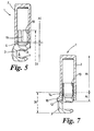
- Fig. 5 is a view similar to that of Fig. 4 but to a smaller scale and showing an alternative means of joining the components of the piston together; and
- Fig. 6 is a view similar to that of Fig. 5 but showing another means of joining the components of the piston together and a further modification.
-
- In all the drawings, the same components or components with the same function have been given the same reference numeral.
- A piston 1 for use in a compressor and as shown in Figs. 2 to 5 the drawings comprises a
cylindrical portion 2 at one end and afoot portion 3 at its other end. Thefoot portion 3 comprises a first part which forms an annular cap 4 joined to an end of the cylindrical portion andbridge 5 which defines arecess 6 that can accommodate a bearing (not shown) for a swash or a wobble plate arrangement of the compressor. On either side of therecess 6, are formed first and second part-spherical, pressure-bearingsurfaces cylindrical portion 2 in order, in use, to pull the piston out of a cylinder bore of the compressor whereas those transmitted to thesecond surface 8 are in a direction towards thecylindrical portion 2 in order to push the piston 1 into the bore on the compression stroke of the piston. - In accordance with the invention, the
portions cylindrical portion 2 is made of aluminum (Al) and thefoot portion 3 is made of steel (St), preferably a high-strength steel. As both the first and second bearing surfaces 7 and 8 are formed in the steel foot portion, their surface areas can be made of commensurate size with one another and also significantly smaller that the cross-sectional surface area of thecylindrical portion 2. - As indicated above, if the relative sizes of the first and second pressure-bearing
surfaces - As previously explained, in a
swash plate compressor 20, as shown in Fig. 3, comprising awobble plate arrangement 21 wherein thewobble plate 22 of the arrangement has two degrees of rotary freedom so that it can rotate jointly with aswash plate 23 and also rotate relative to theswash plate 23, the size of the hemi-spherical slidingshoes surfaces shoes compressor 20 because the inner and outer diameters, ID and OD respectively, of the compressor housing 26 can also be reduced with consequent cost and space savings. - Making the piston 1 in at least two
portions cylindrical portion 2 of the piston 1 is best produced using turning machinery as accuracy of its cylindrical surface is most important. In contrast, thefoot portion 3 is best produced using milling machinery because of the various surfaces, such as thesurfaces foot portion 3 but may also include an anti-rotation locking means (see below) may also be surface hardened prior to being joined to the other piston parts to form the finished piston 1. - In a first embodiment, as shown in Figs. 3 and 4, the
cylindrical portion 2 comprises a hollow aluminum cylinder which is closed at itshead 9 but closed by the annular cap 4 of asteel foot portion 3 at its other end. In this embodiment, thefoot portion 3 is provided with askirt 10 that is force- or press-fitted into the hollowcylindrical portion 2 so that thefoot portion 3 is jointed to thecylindrical portion 2 around the cap 4. Alternatively or in addition, thefoot portion 3 may be bonded to thecylindrical portion 2, for example by fusion, welding, brazing or by application of a suitable adhesive or cementitious material in the joint between the annular cap 4 and the end of thecylindrical portion 2. - In a second embodiment, as shown in Fig. 5, the
skirt 10 of thefoot portion 2 comprises a slotted spring member definingaxial slots 11 which is force fitted into the hollowcylindrical portion 2 and thereafter exerts outward radial forces on thecylindrical portion 2 to retain itself in position. - As a result of the differences in the coefficient of thermal expansion between the different materials used for the parts of the piston 1, such as the
cylindrical portion 2 and thefoot portion 3, it is preferable in both of the above embodiments if, after these two portions have been force fitted together, they can be integrated more closely by some form of metallurgical bonding process. The most suitable bonding process are a friction fusion process or a magnetic pulse welding. Both of these processes are highly suitable for joining a component made of aluminum to one made of steel because they can cope with high loads. - Friction fusion is not friction welding in the conventional sense. In this process rotation-symmetric aluminum and steel components of tubular or full cross-sections are joined using friction at a temperature below the melting point of aluminum while the aluminium component is still solid but in a plasticized state. When in this state, the two components can then be joined by force. The fact that this process does not rely on a molten phase between the two components makes it highly suitable for a piston, which after joining must retain with some accuracy the previously machined surfaces of the two components. The effective friction time, from component contact to the halting of the rotational movement, may only amount to 0.3 seconds, which corresponds to between 1 and 4 component revolutions.
- The join between the
steel skirt 10 of thefoot portion 3 and the inner surface defined by the aluminumcylindrical portion 2 of a piston 1 as described above is eminently suitable for being joined by a friction fusion process. The aluminumcylindrical portion 2 expands during plasticization and fuses solidly on theinner steel skirt 10. - Tests have been carried out using various aluminum alloys and 42CrMo4 steel. Good results were found with AlMgSi1 aluminum, as would be expected, but surprisingly good results were also found with AHS-2 and AlCuMg2 aluminum alloys, where the tensile strength of the steel/aluminum joints were found respectively to be 220 N/mm2 and 336 N/mm2.
- Also, friction fusion permits materials other than aluminum and steel to be used for the
portions - As indicated above, an alternative to friction fusion is magnetic pulse welding. This is a cold welding process that again offers the advantage of not requiring a molten phase between the two components, which can again be of different materials. Also, the welded joint is stronger than the weaker of the two materials being joined.
- In magnetic pulse welding, the welded joint is formed between two overlapping tubes, one being at least partially inserted into the other. It will be appreciated that it is therefore suitable for an arrangement as shown in Fig. 5 where the
steel skirt 10 of thefoot portion 3 is inserted into the hollow aluminumcylindrical portion 2 of the piston 1. The process involves the discharge of a very high current, which may be up to 2 million amps in some instances, in an extremely short period of time, for example in less than 100 microseconds, through a coil that surrounds the components to be welded. The coil does not contact the components but the discharged current induces a very high eddy current in the outer component, in this case thealuminum cylindrical component 2, which as a result collapses and welds itself to the inner component, in this case theskirt 10. It will be appreciated that both the current in the coil and the eddy current in the outer component create very strong magnetic fields but in opposing directions so that they repel one another. As the coil is stronger than thecylindrical portion 2, theportion 2 moves away from the coil at a high velocity, which is above its elastic limit, so that it becomes plastic and as a result collapses onto the inner tube to form the welded joint. The actual welding process last less than 100 microseconds and as a gap is needed between the components for the process to work, tight tolerances between theskirt 10 and thecylindrical portion 2 are not required. - Magnetic pulse welding is a cold process because it happens so rapidly. As a result, the components are heated to no more than 30°C, which is too low to cause any degradation of the metals involved. Also, the welded joint becomes the strongest part of the assembly. It can be used with any material that is conductive and is therefore eminently suitable to weld aluminum to steel. However, many other dissimilar and similar metals can be successfully welded, as well as the joining of metals to non-metals, where a metallurgical bond is not required, for example a ceramic/metal joint as indicated above with reference to the friction fusion process.
- Friction welding could also be used to join a hollow or solid
cylindrical portion 2 to the cap 4 of afoot portion 3, each defining a complementary flat,cross-section surface 13, as shown in Fig. 6. In this case the two flat, apposed surfaces 13, perpendicular to the longitudinal axis of the piston, are joined as shown. Friction welding can cope with high loads and also has the advantage that it does not rely on a molten phase between the two components. The join between the annular cap 4 of thefoot portion 3 and the annular edge defined by thecylindrical portion 2 of a piston 1 is eminently suitable for being welded by a friction welding process, small beads (not shown) forming in the process on the inside, if the cylinder is hollow, and on outside of the joint. - Fig. 7 shows a different method of joining the
cylindrical portion 2 to thefoot portion 3 in which theskirt 10 of thefoot portion 3 and the interior cylindrical surface of the hollowcylindrical portion 2 are provided withcomplementary screw threads 12 so that the twoportions cylindrical portion 2 may be tapped in order that the twoportions 2 and 4 can be joined together by the use of mechanical fasteners, such as screws. - A piston according to the invention can also be further modified, as also shown in Fig. 7, by the addition of an
additional part 14 comprising an anti-rotation lock means located between thefoot portion 3 and thecylindrical portion 2. The lock means comprises aring 14 provided with at least one and preferably twolateral projections 15, which may comprise symmetrical wings, that support the piston 1 against an adjacent wall surface of a casing of the compressor and thereby inhibit rotation of the piston about its longitudinal axis. Theprojections 15 need not be made excessively thick as they will not be subjected to bending moments because they project outwards from the main body of the piston 1. This helps to keep the overall weight of the piston 1 low. - The ring comprising the lock means 14 is preferably fitted to the
foot portion 3 of the piston 1 in the same manner as thecylindrical portion 2. In the illustrated example, the inner annular face of thering 3 is also provided with a screw thread in order that it can be screwed onto theskirt 10 of thefoot portion 3. Alternatively, it could be force fitted on to a slottedspring skirt 10 prior to thecylindrical portion 2, as described above with reference to Fig. 5, and, if necessary, thereafter friction fused to both the cylindrical andfoot portions - The
ring 14 can be made of either aluminium or steel but should preferably be made of the same material as the casing of the compressor in order to reduce wear between those parts of thering 13, such as theprojections 15, which will contact the surface of the casing. In any event, in order to keep frictional forces between thefoot portion 3 and the casing to a minimum, at least thefoot portion 3 and, if provided, thering 14 can be provided with a friction-reducing coating, such as a polytetrafluoroethylene (PTFE) coating or an anti-friction lacquer coating.
Claims (35)
- A piston (1) for use in a compressor for a vehicle air conditioning system comprising a cylindrical portion (2) at one end and a foot portion (3) at its other end, which foot portion (3) can accommodate a bearing for a swash or wobble plate arrangement (21) of a compressor (20),
characterised in that
the piston (1) has been made from at least two individual parts which have been joined together after separate manufacture, the cylindrical portion (2) and the foot portion (3) being two of these parts and being made of different materials from one another. - A piston (1) as claimed in Claim 1,
characterised in that
at least one of the parts (2, 3) is made from steel and at least one other is made from a lighter-weight metal. - A piston (1) as claimed in Claim 2,
characterised in that
the one part made from steel is made from a high-strength steel and the other part is made from aluminum. - A piston as claimed in Claim 2 or Claim 3,
characterised in that
the part made from steel has been surface hardened. - A piston (1) as claimed in any of Claims 1 to 4,
characterised in that
the cylindrical portion (2) is made for aluminum and the foot portion (3) is made from steel. - A piston (1) as claimed in any of Claims 1 to 5,
characterised in that
it comprises only two parts in the form of the cylindrical portion (2) and the foot portion (3) which are joined together after separate manufacture. - A piston (1) as claimed in any of Claims 1 to 5,
characterised in that
a part comprising an anti-rotation lock means (13) is located between the foot portion (3) and the cylindrical portion (2). - A piston (1) as claimed in Claim 7,
characterised in that
the anti-rotation locking means (13) comprises a ring provided with a radial projection (14). - A piston (1) as claimed in any of Claims 1 to 8,
characterised in that
the cylindrical portion (2) is hollow. - A piston (1) as claimed in Claim 9,
characterised in that
the foot portion (3) comprises an annular cap (4) which closes an open end of the hollow cylindrical portion (2) when joined thereto. - A piston (1) as claimed in Claim 9 or Claim 10,
characterised in that
the foot portion (3) comprises a skirt (10) which is fitted inside the hollow cylindrical portion (2). - A piston (1) as claimed in any of Claims 1 to 11,
characterised in that
the foot portion (3) defines a recess (6) into which a swash or wobble plate arrangement can extend. - A piston (1) as claimed in Claim 12,
characterised in that
the foot portion (3) defines a part-spherical, pressure-bearing surface (7) on a side of the recess (6) opposite to that adjacent the cylindrical portion (2), which pressure-bearing surface (7) transmits translational forces to the piston (1) in a direction away from the cylindrical portion (2). - A piston (1) as claimed in Claim 13,
characterised in that
the foot portion (3) defines a second part-spherical, pressure-bearing surface (8) on a side of the recess (6) adjacent the cylindrical portion (2), which pressure-bearing surface (8) transmits translational forces to the piston (1) in a direction towards the cylindrical portion (2). - A piston (1) as claimed in Claim 14,
characterised in that
the second part-spherical pressure-bearing surface (8) has a surface area which is substantially smaller than the cross-sectional surface area of the cylindrical portion (2). - A piston (1) as claimed in Claim 14 or Claim 15,
characterised in that
the second part-spherical, pressure-bearing surface (8) has a surface area that is commensurate with that of the first part-spherical, pressure-bearing surface (7). - A piston (1) as claimed in any of Claims 1 to 16,
characterised in that
it comprises two parts (2, 3) which have been joined together by force fitment. - A piston (1) as claimed in any of Claims 1 to 17,
characterised in that
it comprises two parts (2, 3) which have been bonded together to integrate the two parts into a unitary whole. - A piston (1) as claimed in Claim 18,
characterised in that
the two parts (2, 3) have been bonded together by the use of an adhesive material applied between the two parts (2, 3). - A piston (1) as claimed in Claim 19,
characterised in that
the adhesive material comprises a cementitious material. - A piston (1) as claimed in Claim 18,
characterised in that
the two parts (2, 3) have been joined together by brazing. - A piston (1) as claimed in Claim 18,
characterised in that
the two parts (2, 3) have been joined together by a friction fusion process. - A piston (1) as claimed in Claim 18,
characterised in that
the two parts (2, 3) have been joined together by a welding process. - A piston (1) as claimed in Claim 23,
characterised in that
the two parts (2, 3) have been joined together by magnetic pulse welding. - A piston (1) as claimed in any of Claims 1 to 17,
characterised in that
it comprises two parts (2, 3) which are joined together by a mechanical means (12). - A piston (1) as claimed in Claim 25,
characterised in that
the two parts (2,3 )are joined together by a threaded engagement (12). - A piston (1) as claimed in Claim 25,
characterised in that
the two parts (2, 3) are joined together by mechanical fasteners. - A piston (1) as claimed in any of Claims 1 to 27,
characterised in that
it comprises two parts (2, 3) which have been joined together and which have subsequently been at least partially coated with a friction-reducing coating. - A piston (1) as claimed in any of Claim 28,
characterised in that
the coating comprises a polytetrafluoroethylene (PTFE) coating or an anti-friction lacquer coating. - A swash or wobble plate compressor (20) for a vehicle air conditioning system comprising a piston (1) as claimed in any of Claims 1 to 29.
- A compressor (20) for a vehicle air conditioning system comprising a drive shaft, a swash or wobble plate arrangement (21) operatively connected to the drive shaft, a piston (1) with a cylindrical portion (2) at one end and a foot portion (3) at its other end, a cylinder in which the cylindrical portion (2) can be reciprocated, and a bearing (24, 25) accommodated in the foot portion (3) that cooperates with the swash or wobble plate arrangement (21) to reciprocate the piston (1) as the drive shaft rotates,
characterised in that
the piston (1) has been made from at least two individual parts (2, 3) which have been joined together after separate manufacture, the cylindrical portion (2) and the foot portion (3) being two of these parts and being made of different materials form one another. - A compressor (20) as claimed in Claim 31,
characterised in that
it comprises a wobble plate arrangement (21) comprising a swash plate (23) on which a wobble plate (22) is rotatable mounted. - A compressor (20) as claimed in Claim 32,
characterised in that
the wobble plate (22) has two degrees of rotary freedom so that it can rotate jointly with the swash plate (23) and rotate relative to the swash plate (23). - A compressor (20) as claimed in any of Claims 31 to 33,
characterised in that
it has been designed for the compression of CO2. - A compressor (20) as claimed in any of Claims 31 to 33,
characterised in that
it has been designed for the compression of R134A.
Priority Applications (2)
| Application Number | Priority Date | Filing Date | Title |
|---|---|---|---|
| DE2002623522 DE60223522T2 (en) | 2002-07-26 | 2002-07-26 | pistons compressor |
| EP20020016798 EP1384886B1 (en) | 2002-07-26 | 2002-07-26 | A piston for a compressor |
Applications Claiming Priority (1)
| Application Number | Priority Date | Filing Date | Title |
|---|---|---|---|
| EP20020016798 EP1384886B1 (en) | 2002-07-26 | 2002-07-26 | A piston for a compressor |
Publications (2)
| Publication Number | Publication Date |
|---|---|
| EP1384886A1 true EP1384886A1 (en) | 2004-01-28 |
| EP1384886B1 EP1384886B1 (en) | 2007-11-14 |
Family
ID=29797198
Family Applications (1)
| Application Number | Title | Priority Date | Filing Date |
|---|---|---|---|
| EP20020016798 Expired - Lifetime EP1384886B1 (en) | 2002-07-26 | 2002-07-26 | A piston for a compressor |
Country Status (2)
| Country | Link |
|---|---|
| EP (1) | EP1384886B1 (en) |
| DE (1) | DE60223522T2 (en) |
Cited By (2)
| Publication number | Priority date | Publication date | Assignee | Title |
|---|---|---|---|---|
| WO2007147381A1 (en) * | 2006-06-24 | 2007-12-27 | Ixetic Mac Gmbh | Reciprocating-piston machine |
| WO2008014995A1 (en) * | 2006-08-03 | 2008-02-07 | Eto Magnetic Gmbh | Electromagnetic actuating apparatus |
Families Citing this family (1)
| Publication number | Priority date | Publication date | Assignee | Title |
|---|---|---|---|---|
| DE10360352B4 (en) * | 2003-12-22 | 2016-03-24 | Volkswagen Ag | Swash plate compressor for a CO2 air conditioning system with a gap thickness of 5 to 20 μm between the reciprocating piston and the compression cylinder |
Citations (3)
| Publication number | Priority date | Publication date | Assignee | Title |
|---|---|---|---|---|
| JPH10176657A (en) * | 1996-12-19 | 1998-06-30 | Denso Corp | Swash plate type compressor |
| EP0959227A2 (en) * | 1998-05-20 | 1999-11-24 | Kabushiki Kaisha Toyoda Jidoshokki Seisakusho | Piston and method of manufacture |
| EP1022463A2 (en) * | 1999-01-20 | 2000-07-26 | Kabushiki Kaisha Toyoda Jidoshokki Seisakusho | Piston for fluid machines |
-
2002
- 2002-07-26 DE DE2002623522 patent/DE60223522T2/en not_active Expired - Fee Related
- 2002-07-26 EP EP20020016798 patent/EP1384886B1/en not_active Expired - Lifetime
Patent Citations (3)
| Publication number | Priority date | Publication date | Assignee | Title |
|---|---|---|---|---|
| JPH10176657A (en) * | 1996-12-19 | 1998-06-30 | Denso Corp | Swash plate type compressor |
| EP0959227A2 (en) * | 1998-05-20 | 1999-11-24 | Kabushiki Kaisha Toyoda Jidoshokki Seisakusho | Piston and method of manufacture |
| EP1022463A2 (en) * | 1999-01-20 | 2000-07-26 | Kabushiki Kaisha Toyoda Jidoshokki Seisakusho | Piston for fluid machines |
Non-Patent Citations (1)
| Title |
|---|
| PATENT ABSTRACTS OF JAPAN vol. 1998, no. 11 30 September 1998 (1998-09-30) * |
Cited By (3)
| Publication number | Priority date | Publication date | Assignee | Title |
|---|---|---|---|---|
| WO2007147381A1 (en) * | 2006-06-24 | 2007-12-27 | Ixetic Mac Gmbh | Reciprocating-piston machine |
| WO2008014995A1 (en) * | 2006-08-03 | 2008-02-07 | Eto Magnetic Gmbh | Electromagnetic actuating apparatus |
| US8203405B2 (en) | 2006-08-03 | 2012-06-19 | Eto Magnetic Gmbh | Electromagnetic actuating apparatus |
Also Published As
| Publication number | Publication date |
|---|---|
| DE60223522D1 (en) | 2007-12-27 |
| DE60223522T2 (en) | 2008-09-04 |
| EP1384886B1 (en) | 2007-11-14 |
Similar Documents
| Publication | Publication Date | Title |
|---|---|---|
| US6381842B2 (en) | Method of producing swash plate type compressor piston | |
| AU663615B2 (en) | Variable displacement piston type compressor | |
| US5974946A (en) | Swash plate type compressor using swash plate made of highly wear-resistant material | |
| US5218763A (en) | Method for manufacturing a swaged piston assembly for an automotive air conditioning compressor | |
| US6186048B1 (en) | Variable displacement compressor | |
| EP0959227A2 (en) | Piston and method of manufacture | |
| US6499387B2 (en) | Unified multi-piece piston and method of manufacture | |
| US6415705B1 (en) | Swash plate type compressor piston whose end section is formed of a material different from that of swash-plate engaging portion | |
| EP1134413A2 (en) | Swash plate for compressor | |
| EP1384886A1 (en) | A piston for a compressor | |
| CN1290814A (en) | Method for producing compressor piston | |
| KR19990029231A (en) | Variable Capacity Inclined Plate Compressors | |
| CN85109278A (en) | Have the ball of plastic deformation connection and the joint of axle | |
| EP2134991B1 (en) | Pinless cranktrain for internal combustion engines and compressors | |
| JPH07293326A (en) | Piston structure for internal combustion engine and manufacture thereof | |
| US5743222A (en) | Valve lifter | |
| JP2001041150A (en) | Method of forming coating in mechanical part | |
| EP1126166A2 (en) | Hollow piston for a compressor | |
| EP1087136B1 (en) | Chamfered swash plate compressor piston head | |
| US6438834B1 (en) | Method of making a swash plate type compressor piston whose head portion is formed by pore-free die-casting | |
| EP1249604A1 (en) | A piston for a swash plate compressor | |
| US6378416B1 (en) | Swash plate type compressor piston wherein inner surface of hollow cylindrical section of body portion has axially extending reinforcing projections | |
| JP2000303904A (en) | Manufacture of internal combustion engine piston | |
| JP2768536B2 (en) | Axial plunger pump | |
| JP2001099063A (en) | Method of manufacturing piston for compressor |
Legal Events
| Date | Code | Title | Description |
|---|---|---|---|
| PUAI | Public reference made under article 153(3) epc to a published international application that has entered the european phase |
Free format text: ORIGINAL CODE: 0009012 |
|
| 17P | Request for examination filed |
Effective date: 20030220 |
|
| AK | Designated contracting states |
Kind code of ref document: A1 Designated state(s): AT BE BG CH CY CZ DE DK EE ES FI FR GB GR IE IT LI LU MC NL PT SE SK TR |
|
| AX | Request for extension of the european patent |
Extension state: AL LT LV MK RO SI |
|
| AKX | Designation fees paid |
Designated state(s): CZ DE FR GB |
|
| RAP1 | Party data changed (applicant data changed or rights of an application transferred) |
Owner name: ZEXEL VALEO COMPRESSOR EUROPE GMBH |
|
| RAP1 | Party data changed (applicant data changed or rights of an application transferred) |
Owner name: VALEO COMPRESSOR EUROPE GMBH |
|
| GRAP | Despatch of communication of intention to grant a patent |
Free format text: ORIGINAL CODE: EPIDOSNIGR1 |
|
| GRAS | Grant fee paid |
Free format text: ORIGINAL CODE: EPIDOSNIGR3 |
|
| GRAA | (expected) grant |
Free format text: ORIGINAL CODE: 0009210 |
|
| AK | Designated contracting states |
Kind code of ref document: B1 Designated state(s): CZ DE FR GB |
|
| REG | Reference to a national code |
Ref country code: GB Ref legal event code: FG4D |
|
| REF | Corresponds to: |
Ref document number: 60223522 Country of ref document: DE Date of ref document: 20071227 Kind code of ref document: P |
|
| PG25 | Lapsed in a contracting state [announced via postgrant information from national office to epo] |
Ref country code: CZ Free format text: LAPSE BECAUSE OF FAILURE TO SUBMIT A TRANSLATION OF THE DESCRIPTION OR TO PAY THE FEE WITHIN THE PRESCRIBED TIME-LIMIT Effective date: 20071114 |
|
| ET | Fr: translation filed | ||
| PLBE | No opposition filed within time limit |
Free format text: ORIGINAL CODE: 0009261 |
|
| STAA | Information on the status of an ep patent application or granted ep patent |
Free format text: STATUS: NO OPPOSITION FILED WITHIN TIME LIMIT |
|
| 26N | No opposition filed |
Effective date: 20080815 |
|
| PGFP | Annual fee paid to national office [announced via postgrant information from national office to epo] |
Ref country code: FR Payment date: 20080711 Year of fee payment: 7 |
|
| PGFP | Annual fee paid to national office [announced via postgrant information from national office to epo] |
Ref country code: DE Payment date: 20080926 Year of fee payment: 7 |
|
| GBPC | Gb: european patent ceased through non-payment of renewal fee |
Effective date: 20080726 |
|
| PG25 | Lapsed in a contracting state [announced via postgrant information from national office to epo] |
Ref country code: GB Free format text: LAPSE BECAUSE OF NON-PAYMENT OF DUE FEES Effective date: 20080726 |
|
| REG | Reference to a national code |
Ref country code: FR Ref legal event code: ST Effective date: 20100331 |
|
| PG25 | Lapsed in a contracting state [announced via postgrant information from national office to epo] |
Ref country code: FR Free format text: LAPSE BECAUSE OF NON-PAYMENT OF DUE FEES Effective date: 20090731 |
|
| PG25 | Lapsed in a contracting state [announced via postgrant information from national office to epo] |
Ref country code: DE Free format text: LAPSE BECAUSE OF NON-PAYMENT OF DUE FEES Effective date: 20100202 |