EP1384441A1 - A radiation exposure limiting scheme - Google Patents
A radiation exposure limiting scheme Download PDFInfo
- Publication number
- EP1384441A1 EP1384441A1 EP03254497A EP03254497A EP1384441A1 EP 1384441 A1 EP1384441 A1 EP 1384441A1 EP 03254497 A EP03254497 A EP 03254497A EP 03254497 A EP03254497 A EP 03254497A EP 1384441 A1 EP1384441 A1 EP 1384441A1
- Authority
- EP
- European Patent Office
- Prior art keywords
- imaging system
- radiation
- image data
- entry location
- patient
- Prior art date
- Legal status (The legal status is an assumption and is not a legal conclusion. Google has not performed a legal analysis and makes no representation as to the accuracy of the status listed.)
- Granted
Links
Images



Classifications
-
- A—HUMAN NECESSITIES
- A61—MEDICAL OR VETERINARY SCIENCE; HYGIENE
- A61B—DIAGNOSIS; SURGERY; IDENTIFICATION
- A61B6/00—Apparatus or devices for radiation diagnosis; Apparatus or devices for radiation diagnosis combined with radiation therapy equipment
- A61B6/10—Safety means specially adapted therefor
- A61B6/107—Protection against radiation, e.g. shielding
-
- A—HUMAN NECESSITIES
- A61—MEDICAL OR VETERINARY SCIENCE; HYGIENE
- A61B—DIAGNOSIS; SURGERY; IDENTIFICATION
- A61B6/00—Apparatus or devices for radiation diagnosis; Apparatus or devices for radiation diagnosis combined with radiation therapy equipment
- A61B6/12—Arrangements for detecting or locating foreign bodies
Definitions
- This invention relates generally to a radiation exposure limiting scheme and more particularly to a radiation exposure limiting scheme for reducing the radiation exposure of a physician during the operation of an imaging system.
- an x-ray source projects a fan-shaped, or a cone-shaped, beam which is collimated to lie within an X-Y-Z volume of a Cartesian coordinate system, wherein the X-Y-Z volume is generally referred to as an "imaging volume” and usually includes a set of X-Y planes generally referred to as the "imaging planes".
- An array of radiation detectors wherein each radiation detector includes a detector element, are disposed within the CT system so as to received this beam.
- An object such as a patient, is disposed within the imaging plane so as to be subjected to the x-ray beam wherein the x-ray beam passes through the object.
- the x-ray beam As the x-ray beam passes through the object being imaged, the x-ray beam becomes attenuated before impinging upon the array of radiation detectors.
- the intensity of the attenuated beam radiation received at the detector array is responsive to the attenuation of the x-ray beam by the object, wherein each detector element produces a separate electrical signal responsive to the beam attenuation at the detector element location.
- These electrical signals are referred to as x-ray attenuation measurements.
- the x-ray source and the detector array may be rotated, with a gantry within the imaging volume, around the object to be imaged so that the angle at which the x-ray beam intersects the object constantly changes.
- a group of x-ray attenuation measurements, i.e., projection data, from the detector array at one gantry angle is referred to as a "view”.
- a "scan" of the object comprises a set of views made at different gantry angles during one revolution of the x-ray source and the detector array.
- the projection data is processed so as to construct an image that corresponds to two-dimensional slices taken through the object.
- filtered back-projection technique One method for reconstructing an image from a set of projection data is referred to as the "filtered back-projection technique”.
- This process converts the attenuation measurements from a scan into discrete integers, ranging from - 1024 to +3072, called “CT numbers” or “Hounsfield Units” (HU). These HU's are used to control the brightness of a corresponding pixel on a cathode ray tube or a computer screen display in a manner responsive to the attenuation measurements.
- an attenuation measurement for air may convert into an integer value of ⁇ 1000HU's (corresponding to a dark pixel) and an attenuation measurement for very dense bone matter may convert into an integer value of +3000 (corresponding to a bright pixel), whereas an attenuation measurement for water may convert into an integer value of 0HU's (corresponding to a gray pixel).
- This integer conversion, or "scoring" allows a physician or a technician to determine the density of matter based on the intensity of the computer display.
- an interventional procedure such as a needle biopsy or a needle aspiration, is usually performed to obtain tissue samples needed to determine whether the mass is cancerous or benign.
- a needle controlled by a physician is guided to the mass using simultaneous images, such as fluoro images, produced by the imaging system. This allows a physician to manipulate the needle tip towards the suspected tumor tissue so as to obtain a tissue sample that may be used for analysis.
- an interventional procedure using an imaging system is an excellent diagnostic and evaluation tool
- the physician's hand is exposed to radiation emitted from the imaging system.
- the cumulative radiation dose exposure to the physician's hand over time may become quite large.
- One method to address the problem of physician radiation dose exposure includes minimizing the emitter current of the imaging system and using special forceps to keep the physician's hands out of the radiation beam.
- forceps have not been well received by the medical community because they restrict the tactile sensitivity and thus limits the delicate physician control required for interventional procedures.
- minimizing the emitter current of the imaging system during an interventional procedure while still providing sufficient radiation for qualitative image generation still results in a significant cumulative radiation dose to the physician repeatedly performing the interventional procedures. As such, these methods are not well suited for repeated interventional procedures.
- a method for reducing radiation exposure from an imaging system comprising: determining an entry location; operating the imaging system so as to cause the imaging system to emit radiation having a radiation intensity; controlling the radiation intensity in a manner responsive to the entry location so as to create image data; and processing the image data so as to create processed image data.
- a medium encoded with a machine-readable computer program code for reducing radiation exposure from an imaging system including instructions for causing a controller to implement the aforementioned method.
- a method for reducing radiation exposure from an imaging system comprising: obtaining an object to be scanned; operating the imaging system so as to create image data; displaying the image data on an output device; and processing the image data using a processing device, wherein the processing device, determines an entry location; operates the imaging system so as to cause the imaging system to emit radiation having a radiation intensity; controls the radiation intensity in a manner responsive to the entry location so as to create image data; and processes the image data so as to create processed image data.
- a system for reducing radiation exposure from an imaging system comprising: a gantry having an x-ray source and a radiation detector array, wherein the gantry defines a patient cavity and wherein the x-ray source and the radiation detector array are rotatingly associated with the gantry so as to be separated by the patient cavity; a patient support structure movingly associated with the gantry so as to allow communication with the patient cavity; and a processing device, wherein the processing device, determines an entry location; operates the imaging system so as to cause the imaging system to emit radiation having a radiation intensity; controls the radiation intensity in a manner responsive to the entry location so as to create image data; and processes the image data so as to create processed image data.
- a system for reducing radiation exposure from an imaging system comprising: an imaging system; a patient support structure movingly associated with the imaging system so as to allow communication between the imaging system and a patient, wherein the imaging system generates image data responsive to the patient; and a processing device, wherein the processing device, determines an entry location; operates the imaging system so as to cause the imaging system to emit radiation having a radiation intensity; controls the radiation intensity in a manner responsive to the entry location so as to create image data; and processes the image data so as to create processed image data.
- a representative CT imaging system 1 is shown and preferably includes a gantry 2 having an x-ray source 4, a radiation detector array 6, a patient support structure 8 and a patient cavity 10, wherein x-ray source 4 and radiation detector array 6 are opposingly disposed so as to be separated by patient cavity 10.
- a patient 12 is preferably disposed upon patient support structure 8 which is then disposed within patient cavity 10.
- X-ray source 4 projects an x-ray beam 14 toward radiation detector array 6 so as to pass through patient 12.
- X-ray beam 14 is preferably collimated by a collimate (not shown) so as to lie within an X-Y-Z volume of a Cartesian coordinate system referred to as an "imaging volume".
- Radiation detector array 6 preferably includes a plurality of detector elements 18 wherein each of the detector elements 18 receives attenuated x-ray beam 16 and produces an electrical signal responsive to the intensity of attenuated x-ray beam 16.
- the embodiments described herein are described as applying to a computed tomography imaging system 1, it should be stated that the embodiments described herein may be applied to any imaging system suitable to the desired end purpose, such as an imaging system having a stationary ring and/or arc of detector arrays which surround the patient cavity, wherein the radiation source moves around patient 12 irradiating the detector elements within the stationary ring and/or arc.
- x-ray source 4 and radiation detector array 6 are preferably rotatingly disposed relative to gantry 2 and patient support structure 8, so as to allow x-ray source 4 and radiation detector array 6 to rotate around patient support structure 8 when patient support structure 8 is disposed within patient cavity 10.
- X-ray projection data is obtained by rotating x-ray source 4 and radiation detector array 6 around patient 12 during a scan.
- X-ray source 4 and radiation detector array 6 are preferably communicated with a control mechanism 20 associated with CT imaging system 1.
- Control mechanism 20 preferably controls the rotation and operation of x-ray source 4 and/or radiation detector array 6.
- Control mechanism 20 preferably includes an x-ray controller 22 communicated with x-ray source 4, a gantry motor controller 24, and a data acquisition system (DAS) 26 communicated with radiation detector array 6, wherein x-ray controller 22 provides power and timing signals to x-ray source 4, gantry motor controller 24 controls the rotational speed and angular position of x-ray source 4 and radiation detector array 6 and DAS 26 receives the electrical signal data produced by detector elements 18 and converts this data into digital signals for subsequent processing.
- CT imaging system 1 also preferably includes an image reconstruction device 28, a data storage device 30 and a processing device 32, wherein processing device 32 is communicated with image reconstruction device 28, gantry motor controller 24, x-ray controller 22, data storage device 30, an input device 34 and an output device 36.
- CT imaging system 1 also preferably includes a table controller 38 communicated with processing device 32 and patient support structure 8, so as to control the position of patient support structure 8 relative to patient cavity 10.
- patient 12 is preferably disposed on patient support structure 8, which is then positioned by an operator via processing device 32 so as to be disposed within patient cavity 10.
- Gantry motor controller 24 is operated via processing device 32 so as to cause x-ray source 4 and radiation detector array 6 to rotate relative to patient 12.
- X-ray controller 22 is operated via processing device 32 so as to cause x-ray source 4 to emit and project a collimated x-ray beam 14 toward radiation detector array 6 and hence toward patient 12.
- X-ray beam 14 passes through patient 12 so as to create an attenuated x-ray beam 16, which is received by radiation detector array 6.
- Detector elements 18 receive attenuated x-ray beam 16, produces electrical signal data responsive to the intensity of attenuated x-ray beam 16 and communicates this electrical signal data to DAS 26.
- DAS 26 then converts this electrical signal data to digital signals and communicates both the digital signals and the electrical signal data to image reconstruction device 28, which performs high-speed image reconstruction.
- This information is then communicated to processing device 32, which stores the image in data storage device 30 and displays the digital signal as an image via output device 36.
- an entry location 40 is determined, as shown in step 102.
- an instrument such as a needle
- entry location 40 represents the location of the physician's hand which is disposed within patient cavity 10 and hence within a radiation field 42, wherein radiation field 42 includes an average radiation distribution 44 and an angular radiation distribution 46.
- entry location 40 may be disposed within a predetermined entry angular range 50.
- entry location 40 is preferably determined via an entry cursor and/or a target location cursor, wherein the entry cursor and/or target location cursor is communicated with processing device 32 via input device 34
- entry location 40 may be determined and/or estimated using any information, method and/or device suitable to the desired end purpose, such as processing of data extracted from a Fluoro scan procedure.
- an on-line assessment of the angular position of entry location 40 (& hence physician's hand) may be performed in a manner responsive to changes of the x-ray attenuation distribution during the intervention process and/or a manner responsive to the x-ray distribution determined during the primary non-fluoro scan and/or in a manner responsive to any other suitable means of detection, such as Ultrasound and/or optical.
- imaging system 1 is operated so as to cause x-ray source 4 to emit radiation in the form of x-ray beam 14.
- x-ray source 4 and radiation detector array 6 rotate around patient cavity 10
- x-ray beam 14 creates radiation field 42 within patient cavity 10 wherein radiation field 42 includes average radiation distribution 44 and angular radiation distribution 46, as shown in step 104.
- the gantry angular position or the angle at which x-ray beam 14 intersects patient 12 varies between 0° and 360°.
- Radiation intensity level 48 is then controlled in a manner responsive to entry location 40 and/or entry angular range 50 so as to create image data, as shown in step 106.
- radiation intensity level 48 is decreased by a predetermined minimization amount so as to minimize the radiation intensity level 48 in the area of entry location 40.
- radiation intensity level 48 is increased by a predetermined minimization amount so as to maximize the radiation intensity level 48 in the area of 180° from entry location 40.
- Predetermined minimization amount may be equal to the radiation intensity level so as to reduce the radiation intensity level at entry location 40 and/or within entry angular range 50 to be zero.
- predetermined minimization amount may be any value suitable to the desired end purpose.
- radiation intensity level 48 is decreased by a predetermined minimization amount so as to minimize the radiation intensity level 48 in the area of entry location 40.
- radiation intensity level 48 is increased by a predetermined minimization amount so as to maximize the radiation intensity level 48 in the area of ⁇ 90° from entry location 40 and/or entry angular range 50. This advantageously allows for a nearly constant average radiation distribution 44 through out the scan while allowing for the angular radiation distribution 46 to be modified.
- radiation intensity level 48 may be controlled by using a predetermined radiation absorption angular profile (as measured during a previous rotation of the fluoroCT process and/or from a previously acquired static scan) as an input for additional modulation of x-ray beam 14 in order to significantly reduce patient radiation exposure dose.
- This pre-determined measure of radiation absorption may be dependent upon the anatomy of patient 12 within the scan field. For example, if patient absorption at specific radiation source angles is low, as may be the case when x-ray source 4 is positioned anterior or posterior to the chest area of patient 12, then the radiation beam intensity may be significantly reduced at these angles without affecting image quality.
- x-ray source 4 may deliver a full un-modulated radiation exposure dose.
- Another related feature includes using the angular current profile as an input for a weighting function in the reconstruction of the image. As the x-ray radiation is reduced the limited photon statistics give rise to increased image noise. Special noise reduction techniques and algorithms may be applied in the reconstruction process to reduce any image performance degradation. These algorithms may be controlled either by obtaining a measure of actual photon statistics during the acquisition process and/or by the priory knowledge of the angular current profile.
- more than 180+fan degrees of data may be used for image reconstruction (e.g. 270 deg).
- the additional data beyond the last 180 degrees of scanning may be used to reduce image noise and streaks and significantly improve the image quality.
- the reduction in temporal resolution that this "over-scan" reconstruction entails may not be significant while using very fast rotation speed ( ⁇ 0.5sec) and a weighting function that includes only a small amount of "old" data.
- more than 360 degrees of data may be used for image reconstruction (e.g. 540 deg).
- This implementation may occur following the 'dynamic' image reconstruction and display phase of FluoroCT imaging and may be used as a means of improving the quality of the final static image that remains on output device 36 after the real-time imaging has stopped.
- the additional data beyond the last 360 degrees of scanning may be used to reduce image noise and streaks and significantly improve the static image quality of this final image.
- the reduction in temporal resolution that this over-scan reconstruction entails may not be significant when viewing the static image at the completion of the FluoroCT procedure.
- the radiation intensity level 48 may also be controlled in a manner responsive to entry location 40 and/or entry angular range 50 so as to prevent radiation from being emitted from imaging system 1 while the gantry angular position approaches the entry location 40 and/or is within entry angular range 50. Radiation may be prevented from being emitted from imaging system 1 via any means suitable to the desired end purpose, such as by an electrical means (switch), a mechanical means (shutter) and/or an electro-mechanical means. This advantageously reduces and/or eliminates radiation exposure to a physician's hand while allowing the interventional procedure to continue. Moreover, direct radiation to the physician's hand will be eliminated while indirect radiation will be dramatically reduced by the absorption of the patient's body.
- This image data is then processed so as to create processed image data, as shown in step 108.
- This advantageously allows for a significant dose reduction to the physician during interventional procedures using a FluoroCT scan while preserving patient dose and image quality.
- This invention advantageously allows for interventional procedures to be performed while minimizing and/or eliminating radiation exposure to the performing physician.
- potential health problems may advantageously be avoided by reducing the physicians' exposure to x-ray radiation to more acceptable levels.
- a method for reducing radiation exposure from an imaging system 100 may be applied by any imaging system suitable to the desired end purpose, such as a magnetic resonance imaging (MRI), ultrasound, X-Ray, CT and/or PET.
- MRI magnetic resonance imaging
- ultrasound ultrasound
- X-Ray X-Ray
- CT computed tomography
- PET PET
- processing of Figure 3 may be implemented through processing device 32 operating in response to a computer program.
- the controller may include, but not be limited to, a processor(s), computer(s), memory, storage, register(s), timing, interrupt(s), communication interfaces, and input/output signal interfaces, as well as combinations comprising at least one of the foregoing.
- the controller may include input signal filtering to enable accurate sampling and conversion or acquisitions of such signals from communications interfaces. It is also considered within the scope of the invention that the processing of Figure 3 may be implemented by a controller located remotely from processing device 32.
- the present invention can be embodied in the form of computer-implemented processes and apparatuses for practicing those processes.
- the present invention can also be embodied in the form of computer program code containing instructions embodied in tangible media, such as floppy diskettes, CD-ROMs, hard drives, or any other computer-readable storage medium, wherein, when the computer program code is loaded into and executed by a computer, the computer becomes an apparatus for practicing the invention.
- Existing systems having reprogrammable storage e.g., flash memory
- the present invention can also be embodied in the form of computer program code, for example, whether stored in a storage medium, loaded into and/or executed by a computer, or transmitted over some transmission medium, such as over electrical wiring or cabling, through fiber optics, or via electromagnetic radiation, wherein, when the computer program code is loaded into and executed by a computer, the computer becomes an apparatus for practicing the invention.
- computer program code segments configure the microprocessor to create specific logic circuits.
Landscapes
- Health & Medical Sciences (AREA)
- Life Sciences & Earth Sciences (AREA)
- Medical Informatics (AREA)
- Engineering & Computer Science (AREA)
- Radiology & Medical Imaging (AREA)
- Biomedical Technology (AREA)
- Biophysics (AREA)
- Nuclear Medicine, Radiotherapy & Molecular Imaging (AREA)
- Optics & Photonics (AREA)
- Pathology (AREA)
- Physics & Mathematics (AREA)
- High Energy & Nuclear Physics (AREA)
- Heart & Thoracic Surgery (AREA)
- Molecular Biology (AREA)
- Surgery (AREA)
- Animal Behavior & Ethology (AREA)
- General Health & Medical Sciences (AREA)
- Public Health (AREA)
- Veterinary Medicine (AREA)
- Apparatus For Radiation Diagnosis (AREA)
Abstract
Description
- This invention relates generally to a radiation exposure limiting scheme and more particularly to a radiation exposure limiting scheme for reducing the radiation exposure of a physician during the operation of an imaging system.
- In at least one known computed tomography (CT) imaging system configuration, an x-ray source projects a fan-shaped, or a cone-shaped, beam which is collimated to lie within an X-Y-Z volume of a Cartesian coordinate system, wherein the X-Y-Z volume is generally referred to as an "imaging volume" and usually includes a set of X-Y planes generally referred to as the "imaging planes". An array of radiation detectors, wherein each radiation detector includes a detector element, are disposed within the CT system so as to received this beam. An object, such as a patient, is disposed within the imaging plane so as to be subjected to the x-ray beam wherein the x-ray beam passes through the object. As the x-ray beam passes through the object being imaged, the x-ray beam becomes attenuated before impinging upon the array of radiation detectors. The intensity of the attenuated beam radiation received at the detector array is responsive to the attenuation of the x-ray beam by the object, wherein each detector element produces a separate electrical signal responsive to the beam attenuation at the detector element location. These electrical signals are referred to as x-ray attenuation measurements.
- In addition, the x-ray source and the detector array may be rotated, with a gantry within the imaging volume, around the object to be imaged so that the angle at which the x-ray beam intersects the object constantly changes. A group of x-ray attenuation measurements, i.e., projection data, from the detector array at one gantry angle is referred to as a "view". A "scan" of the object comprises a set of views made at different gantry angles during one revolution of the x-ray source and the detector array. In an axial scan, the projection data is processed so as to construct an image that corresponds to two-dimensional slices taken through the object.
- One method for reconstructing an image from a set of projection data is referred to as the "filtered back-projection technique". This process converts the attenuation measurements from a scan into discrete integers, ranging from - 1024 to +3072, called "CT numbers" or "Hounsfield Units" (HU). These HU's are used to control the brightness of a corresponding pixel on a cathode ray tube or a computer screen display in a manner responsive to the attenuation measurements. For example, an attenuation measurement for air may convert into an integer value of ―1000HU's (corresponding to a dark pixel) and an attenuation measurement for very dense bone matter may convert into an integer value of +3000 (corresponding to a bright pixel), whereas an attenuation measurement for water may convert into an integer value of 0HU's (corresponding to a gray pixel). This integer conversion, or "scoring" allows a physician or a technician to determine the density of matter based on the intensity of the computer display.
- Once a suspicious mass, such as a tumor, cyst and/or lesion, is discovered an interventional procedure, such as a needle biopsy or a needle aspiration, is usually performed to obtain tissue samples needed to determine whether the mass is cancerous or benign. To do this, a needle controlled by a physician is guided to the mass using simultaneous images, such as fluoro images, produced by the imaging system. This allows a physician to manipulate the needle tip towards the suspected tumor tissue so as to obtain a tissue sample that may be used for analysis.
- However, although an interventional procedure using an imaging system is an excellent diagnostic and evaluation tool, each time an interventional procedure is performed by a physician, the physician's hand is exposed to radiation emitted from the imaging system. As such, if a physician performs a large number of interventional procedures over time, the cumulative radiation dose exposure to the physician's hand over time may become quite large. Given that health problems are known to be related to increasing exposure to radiation there is concern within the medical community that physicians performing these procedures may be over exposed to imaging system radiation.
- One method to address the problem of physician radiation dose exposure includes minimizing the emitter current of the imaging system and using special forceps to keep the physician's hands out of the radiation beam. Unfortunately, forceps have not been well received by the medical community because they restrict the tactile sensitivity and thus limits the delicate physician control required for interventional procedures. Moreover, it has been found that minimizing the emitter current of the imaging system during an interventional procedure while still providing sufficient radiation for qualitative image generation still results in a significant cumulative radiation dose to the physician repeatedly performing the interventional procedures. As such, these methods are not well suited for repeated interventional procedures.
- The above discussed and other drawbacks and deficiencies are overcome or alleviated in accordance with the invention by a method for reducing radiation exposure from an imaging system comprising: determining an entry location; operating the imaging system so as to cause the imaging system to emit radiation having a radiation intensity; controlling the radiation intensity in a manner responsive to the entry location so as to create image data; and processing the image data so as to create processed image data.
- In an alternative embodiment of the invention, a medium encoded with a machine-readable computer program code for reducing radiation exposure from an imaging system, the medium including instructions for causing a controller to implement the aforementioned method.
- In another alternative embodiment, a method for reducing radiation exposure from an imaging system comprising: obtaining an object to be scanned; operating the imaging system so as to create image data; displaying the image data on an output device; and processing the image data using a processing device, wherein the processing device, determines an entry location; operates the imaging system so as to cause the imaging system to emit radiation having a radiation intensity; controls the radiation intensity in a manner responsive to the entry location so as to create image data; and processes the image data so as to create processed image data.
- In another alternative embodiment, a system for reducing radiation exposure from an imaging system comprising: a gantry having an x-ray source and a radiation detector array, wherein the gantry defines a patient cavity and wherein the x-ray source and the radiation detector array are rotatingly associated with the gantry so as to be separated by the patient cavity; a patient support structure movingly associated with the gantry so as to allow communication with the patient cavity; and a processing device, wherein the processing device, determines an entry location; operates the imaging system so as to cause the imaging system to emit radiation having a radiation intensity; controls the radiation intensity in a manner responsive to the entry location so as to create image data; and processes the image data so as to create processed image data.
- In another alternative embodiment, a system for reducing radiation exposure from an imaging system comprising: an imaging system; a patient support structure movingly associated with the imaging system so as to allow communication between the imaging system and a patient, wherein the imaging system generates image data responsive to the patient; and a processing device, wherein the processing device, determines an entry location; operates the imaging system so as to cause the imaging system to emit radiation having a radiation intensity; controls the radiation intensity in a manner responsive to the entry location so as to create image data; and processes the image data so as to create processed image data.
- The above discussed and other features and advantages of the present invention will be appreciated and understood by those skilled in the art from the following detailed description with reference to the drawings, in which:
- Figure 1 is a perspective view of a CT imaging system and a patient disposed for imaging;
- Figure 2 is a block schematic diagram of a CT imaging system;
- Figure 3 is a block diagram describing a method for reducing radiation exposure from an imaging system;
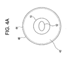
- Figure 4A is a distribution diagram showing the angular radiation distribution of an imaging system;
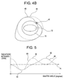
- Figure 4B is a distribution diagram showing the angular radiation distribution of an imaging system in accordance with an exemplary embodiment;
- Figure 5 is a graph of the radiation dose as a function of imaging system gantry angle in accordance with an exemplary embodiment; and
- Figure 6 is a distribution diagram showing the angular radiation distribution of an imaging system in accordance with an exemplary embodiment.
-
- Referring to Figure 1 and Figure 2 a representative
CT imaging system 1 is shown and preferably includes agantry 2 having anx-ray source 4, aradiation detector array 6, apatient support structure 8 and apatient cavity 10, whereinx-ray source 4 andradiation detector array 6 are opposingly disposed so as to be separated bypatient cavity 10. Apatient 12 is preferably disposed uponpatient support structure 8 which is then disposed withinpatient cavity 10.X-ray source 4 projects anx-ray beam 14 towardradiation detector array 6 so as to pass throughpatient 12.X-ray beam 14 is preferably collimated by a collimate (not shown) so as to lie within an X-Y-Z volume of a Cartesian coordinate system referred to as an "imaging volume". After passing through and becoming attenuated bypatient 12, attenuatedx-ray beam 16 is preferably received byradiation detector array 6.Radiation detector array 6 preferably includes a plurality ofdetector elements 18 wherein each of thedetector elements 18 receivesattenuated x-ray beam 16 and produces an electrical signal responsive to the intensity of attenuatedx-ray beam 16. - Although the embodiments described herein are described as applying to a computed
tomography imaging system 1, it should be stated that the embodiments described herein may be applied to any imaging system suitable to the desired end purpose, such as an imaging system having a stationary ring and/or arc of detector arrays which surround the patient cavity, wherein the radiation source moves aroundpatient 12 irradiating the detector elements within the stationary ring and/or arc. - In addition,
x-ray source 4 andradiation detector array 6 are preferably rotatingly disposed relative togantry 2 andpatient support structure 8, so as to allowx-ray source 4 andradiation detector array 6 to rotate aroundpatient support structure 8 whenpatient support structure 8 is disposed withinpatient cavity 10. X-ray projection data is obtained by rotatingx-ray source 4 andradiation detector array 6 aroundpatient 12 during a scan.X-ray source 4 andradiation detector array 6 are preferably communicated with acontrol mechanism 20 associated withCT imaging system 1.Control mechanism 20 preferably controls the rotation and operation ofx-ray source 4 and/orradiation detector array 6. -
Control mechanism 20 preferably includes anx-ray controller 22 communicated withx-ray source 4, agantry motor controller 24, and a data acquisition system (DAS) 26 communicated withradiation detector array 6, whereinx-ray controller 22 provides power and timing signals tox-ray source 4,gantry motor controller 24 controls the rotational speed and angular position ofx-ray source 4 andradiation detector array 6 andDAS 26 receives the electrical signal data produced bydetector elements 18 and converts this data into digital signals for subsequent processing.CT imaging system 1 also preferably includes animage reconstruction device 28, adata storage device 30 and aprocessing device 32, whereinprocessing device 32 is communicated withimage reconstruction device 28,gantry motor controller 24,x-ray controller 22,data storage device 30, an input device 34 and anoutput device 36. Moreover,CT imaging system 1 also preferably includes atable controller 38 communicated withprocessing device 32 andpatient support structure 8, so as to control the position ofpatient support structure 8 relative topatient cavity 10. - In accordance with an exemplary embodiment,
patient 12 is preferably disposed onpatient support structure 8, which is then positioned by an operator viaprocessing device 32 so as to be disposed withinpatient cavity 10.Gantry motor controller 24 is operated viaprocessing device 32 so as to causex-ray source 4 andradiation detector array 6 to rotate relative topatient 12.X-ray controller 22 is operated viaprocessing device 32 so as to causex-ray source 4 to emit and project a collimatedx-ray beam 14 towardradiation detector array 6 and hence towardpatient 12.X-ray beam 14 passes throughpatient 12 so as to create anattenuated x-ray beam 16, which is received byradiation detector array 6. -
Detector elements 18 receive attenuatedx-ray beam 16, produces electrical signal data responsive to the intensity of attenuatedx-ray beam 16 and communicates this electrical signal data toDAS 26.DAS 26 then converts this electrical signal data to digital signals and communicates both the digital signals and the electrical signal data toimage reconstruction device 28, which performs high-speed image reconstruction. This information is then communicated to processingdevice 32, which stores the image indata storage device 30 and displays the digital signal as an image viaoutput device 36. - Referring to Figure 3, a flow diagram describing a method for reducing
radiation exposure 100 from animaging system 1 is shown and discussed. In accordance with an exemplary embodiment, anentry location 40 is determined, as shown instep 102. During an interventional procedure an instrument, such as a needle, is guided by a physician's hand with the help ofimaging system 1 andentry location 40 represents the location of the physician's hand which is disposed withinpatient cavity 10 and hence within aradiation field 42, whereinradiation field 42 includes anaverage radiation distribution 44 and anangular radiation distribution 46. In addition,entry location 40 may be disposed within a predetermined entryangular range 50. Although,entry location 40 is preferably determined via an entry cursor and/or a target location cursor, wherein the entry cursor and/or target location cursor is communicated withprocessing device 32 via input device 34,entry location 40 may be determined and/or estimated using any information, method and/or device suitable to the desired end purpose, such as processing of data extracted from a Fluoro scan procedure. For example, an on-line assessment of the angular position of entry location 40 (& hence physician's hand) may be performed in a manner responsive to changes of the x-ray attenuation distribution during the intervention process and/or a manner responsive to the x-ray distribution determined during the primary non-fluoro scan and/or in a manner responsive to any other suitable means of detection, such as Ultrasound and/or optical. - Referring to Figure 4a,
imaging system 1 is operated so as to causex-ray source 4 to emit radiation in the form ofx-ray beam 14. Asx-ray source 4 andradiation detector array 6 rotate aroundpatient cavity 10x-ray beam 14 createsradiation field 42 withinpatient cavity 10 whereinradiation field 42 includesaverage radiation distribution 44 andangular radiation distribution 46, as shown instep 104. Asx-ray source 4 rotates aroundpatient cavity 10 the gantry angular position or the angle at whichx-ray beam 14 intersectspatient 12, varies between 0° and 360°. - Radiation intensity level 48 is then controlled in a manner responsive to
entry location 40 and/or entryangular range 50 so as to create image data, as shown instep 106. Referring to Figure 4B and Figure 5, for a 360°image reconstruction 52 as the gantry angular position approachesentry location 40 and/or entryangular range 50, radiation intensity level 48 is decreased by a predetermined minimization amount so as to minimize the radiation intensity level 48 in the area ofentry location 40. Similarly, as the gantry angular position approaches 180° fromentry location 40 and/or entryangular range 50, radiation intensity level 48 is increased by a predetermined minimization amount so as to maximize the radiation intensity level 48 in the area of 180° fromentry location 40. Predetermined minimization amount may be equal to the radiation intensity level so as to reduce the radiation intensity level atentry location 40 and/or within entryangular range 50 to be zero. Moreover, predetermined minimization amount may be any value suitable to the desired end purpose. - For a 180°
image reconstruction 60, as the gantry angular position approachesentry location 40 and/or entryangular range 50, radiation intensity level 48 is decreased by a predetermined minimization amount so as to minimize the radiation intensity level 48 in the area ofentry location 40. Similarly, as the gantry angular position approaches ±90° fromentry location 40 and/or entryangular range 50, radiation intensity level 48 is increased by a predetermined minimization amount so as to maximize the radiation intensity level 48 in the area of ±90° fromentry location 40 and/or entryangular range 50. This advantageously allows for a nearly constantaverage radiation distribution 44 through out the scan while allowing for theangular radiation distribution 46 to be modified. This advantageously allows the noise level of the image to be compensated by amplification of the emitter tube current at the opposing angle (180° for 360° recon) or the perpendicular angles (±90° for 180° recon). Moreover, the radiation exposure to the physician's hand will be dramatically reduced by the absorption of the patient's body (and, in most cases, by the patient table). - In addition, radiation intensity level 48 may be controlled by using a predetermined radiation absorption angular profile (as measured during a previous rotation of the fluoroCT process and/or from a previously acquired static scan) as an input for additional modulation of
x-ray beam 14 in order to significantly reduce patient radiation exposure dose. This pre-determined measure of radiation absorption may be dependent upon the anatomy ofpatient 12 within the scan field. For example, if patient absorption at specific radiation source angles is low, as may be the case whenx-ray source 4 is positioned anterior or posterior to the chest area ofpatient 12, then the radiation beam intensity may be significantly reduced at these angles without affecting image quality. Alternatively, when patient absorption is high, as may be the case for lateral radiation source angles, such as through the shoulder area or hip area ofpatient 12,x-ray source 4 may deliver a full un-modulated radiation exposure dose. - Another related feature includes using the angular current profile as an input for a weighting function in the reconstruction of the image. As the x-ray radiation is reduced the limited photon statistics give rise to increased image noise. Special noise reduction techniques and algorithms may be applied in the reconstruction process to reduce any image performance degradation. These algorithms may be controlled either by obtaining a measure of actual photon statistics during the acquisition process and/or by the priory knowledge of the angular current profile.
- Furthermore, in order to eliminate streaks and other noise pattern artifacts, in the fluoro images, more than 180+fan degrees of data may be used for image reconstruction (e.g. 270 deg). The additional data beyond the last 180 degrees of scanning may be used to reduce image noise and streaks and significantly improve the image quality. The reduction in temporal resolution that this "over-scan" reconstruction entails may not be significant while using very fast rotation speed (≤0.5sec) and a weighting function that includes only a small amount of "old" data.
- Furthermore, in order to eliminate streaks and other noise pattern artifacts, in the final (static) image, more than 360 degrees of data may be used for image reconstruction (e.g. 540 deg). This implementation may occur following the 'dynamic' image reconstruction and display phase of FluoroCT imaging and may be used as a means of improving the quality of the final static image that remains on
output device 36 after the real-time imaging has stopped. The additional data beyond the last 360 degrees of scanning may be used to reduce image noise and streaks and significantly improve the static image quality of this final image. The reduction in temporal resolution that this over-scan reconstruction entails may not be significant when viewing the static image at the completion of the FluoroCT procedure. - Referring to Figure 6, the radiation intensity level 48 may also be controlled in a manner responsive to
entry location 40 and/or entryangular range 50 so as to prevent radiation from being emitted fromimaging system 1 while the gantry angular position approaches theentry location 40 and/or is within entryangular range 50. Radiation may be prevented from being emitted fromimaging system 1 via any means suitable to the desired end purpose, such as by an electrical means (switch), a mechanical means (shutter) and/or an electro-mechanical means. This advantageously reduces and/or eliminates radiation exposure to a physician's hand while allowing the interventional procedure to continue. Moreover, direct radiation to the physician's hand will be eliminated while indirect radiation will be dramatically reduced by the absorption of the patient's body. - This image data is then processed so as to create processed image data, as shown in
step 108. This advantageously allows for a significant dose reduction to the physician during interventional procedures using a FluoroCT scan while preserving patient dose and image quality. - This invention advantageously allows for interventional procedures to be performed while minimizing and/or eliminating radiation exposure to the performing physician. In addition, potential health problems may advantageously be avoided by reducing the physicians' exposure to x-ray radiation to more acceptable levels.
- In accordance with an exemplary embodiment, a method for reducing radiation exposure from an
imaging system 100 may be applied by any imaging system suitable to the desired end purpose, such as a magnetic resonance imaging (MRI), ultrasound, X-Ray, CT and/or PET. - In accordance with an exemplary embodiment, processing of Figure 3 may be implemented through
processing device 32 operating in response to a computer program. In order to perform the prescribed functions and desired processing, as well as the computations therefore (e.g., the execution of Fourier analysis algorithm(s), the control processes prescribed herein, and the like), the controller may include, but not be limited to, a processor(s), computer(s), memory, storage, register(s), timing, interrupt(s), communication interfaces, and input/output signal interfaces, as well as combinations comprising at least one of the foregoing. For example, the controller may include input signal filtering to enable accurate sampling and conversion or acquisitions of such signals from communications interfaces. It is also considered within the scope of the invention that the processing of Figure 3 may be implemented by a controller located remotely from processingdevice 32. - As described above, the present invention can be embodied in the form of computer-implemented processes and apparatuses for practicing those processes. The present invention can also be embodied in the form of computer program code containing instructions embodied in tangible media, such as floppy diskettes, CD-ROMs, hard drives, or any other computer-readable storage medium, wherein, when the computer program code is loaded into and executed by a computer, the computer becomes an apparatus for practicing the invention. Existing systems having reprogrammable storage (e.g., flash memory) can be updated to implement the invention. The present invention can also be embodied in the form of computer program code, for example, whether stored in a storage medium, loaded into and/or executed by a computer, or transmitted over some transmission medium, such as over electrical wiring or cabling, through fiber optics, or via electromagnetic radiation, wherein, when the computer program code is loaded into and executed by a computer, the computer becomes an apparatus for practicing the invention. When implemented on a general-purpose microprocessor, the computer program code segments configure the microprocessor to create specific logic circuits.
- For completeness, various aspects of the invention are set out in the following numbered clauses:
- 1. A method for reducing radiation exposure (100) from an imaging
system (1) comprising:
- determining an entry location (40) (102);
- operating the imaging system (1) so as to cause the imaging system (1) to emit radiation having a radiation intensity (48) (104);
- controlling said radiation intensity (48) in a manner responsive to said entry location (40) so as to create image data (106); and
- processing said image data so as to create processed image data (108).
- 2. The method (100) of
clause 1, wherein said determining (102) includes determining said entry location (40) relative to said imaging system (1). - 3. The method (100) of
clause 1, wherein said entry location (40) is determined in a manner responsive to an entry cursor. - 4. The method (100) of
clause 1, wherein said entry location (40) is determined in a manner responsive to a target location cursor. - 5. The method (100) of
clause 1, wherein said entry location (40) is determined in a manner responsive to a FluoroCT scan. - 6. The method (100) of
clause 1, wherein the imaging system (1) includes an object cavity (10) and a radiation source (4) having a gantry angular position, wherein said radiation source (4) is rotatably associated with the imaging system (1) so as to rotate around said object cavity (10) and wherein said entry location (40) includes an entry angular range (50). - 7. The method (100) of
clause 6, wherein said operating (104) includes operating the imaging system (1) so as to cause said radiation source (4) to rotate around said object cavity (10). - 8. The method (100) of
clause 6, wherein said controlling (106) includes controlling said radiation intensity (48) such that said radiation intensity (48) is decreased by a predetermined minimization amount when said gantry angular position is within said entry angular range (50). - 9. The method (100) of
clause 8, wherein said predetermined minimization amount is equal to said radiation intensity (48). - 10. The method (100) of
clause 6, wherein said controlling (106) includes controlling said radiation intensity (48) such that said radiation intensity (48) is increased by a predetermined minimization amount when said gantry angular position is within 180 degrees of said entry angular range (50). - 11. The method (100) of
clause 6, wherein said controlling (106) includes controlling said radiation intensity (48) such that said radiation intensity (48) is increased by a predetermined minimization amount when said gantry angular position is within 90 degrees of said entry angular range (50). - 12. The method (100) of
clause 6, wherein said operating (104) includes operating the imaging system (1) so as to determine a radiation absorption angular profile, wherein said radiation absorption angular profile is responsive to said gantry angular position. - 13. The method (100) of
clause 12, wherein said controlling (106) includes controlling the imaging system (1) so as to modulate said radiation intensity (48) in a manner responsive to said radiation absorption angular profile. - 14. The method (100) of
clause 1, wherein said operating (104) includes operating the imaging system (1) so as to determine an angular current profile. - 15. The method (100) of
clause 14, wherein said processed image data is responsive to said angular current profile. - 16. The method (100) of
clause 6, wherein said operating (104) includes operating the imaging system (1) so as to cause the imaging system (1) to stop emitting radiation when said gantry angular position is within said entry angular range (50). - 17. A medium encoded with a machine-readable computer program code
for reducing radiation exposure from an imaging system (1), said medium
including instructions for causing controller (32) to implement a method
comprising:
- determining an entry location (40) (102);
- operating the imaging system (1) so as to cause the imaging system (1) to emit radiation having a radiation intensity (48) (104);
- controlling said radiation intensity (48) in a manner responsive to said entry location (40) so as to create image data (106); and
- processing said image data so as to create processed image data (108).
- 18. The medium of clause 17, wherein said determining (102) includes determining said entry location (40) relative to said imaging system (1).
- 19. The medium of clause 17, wherein said entry location (40) is determined in a manner responsive to an entry cursor.
- 20. The medium of clause 17, wherein said entry location (40) is determined in a manner responsive to a target location cursor.
- 21. The medium of clause 17, wherein said entry location (40) is determined in a manner responsive to a FluoroCT scan.
- 22. The medium of clause 17, wherein the imaging system (1) includes an object cavity (10) and a radiation source (4) having a gantry angular position, wherein said radiation source (4) is rotatably associated with the imaging system (1) so as to rotate around said object cavity (10) and wherein said entry location (40) includes an entry angular range (50).
- 23. The medium of
clause 22, wherein said operating (104) includes operating the imaging system (1) so as to cause said radiation source (4) to rotate around said object cavity (10). - 24. The medium of
clause 22, wherein said controlling (106) includes controlling said radiation intensity (48) such that said radiation intensity (48) is decreased by a predetermined minimization amount when said gantry angular position is within said entry angular range (50). - 25. The medium of
clause 24, wherein said predetermined minimization amount is equal to said radiation intensity (48). - 26. The medium of
clause 22, wherein said controlling (106) includes controlling said radiation intensity (48) such that said radiation intensity (48) is increased by a predetermined minimization amount when said gantry angular position is within 180 degrees of said entry angular range (50). - 27. The medium of
clause 22, wherein said controlling (106) includes controlling said radiation intensity (48) such that said radiation intensity (48) is increased by a predetermined minimization amount when said gantry angular position is within 90 degrees of said entry angular range (50). - 28. The medium of
clause 22, wherein said operating (104) includes operating the imaging system (1) so as to determine a radiation absorption angular profile, wherein said radiation absorption angular profile is responsive to said gantry angular position. - 29. The medium of
clause 28, wherein said controlling (106) includes controlling the imaging system (1) so as to modulate said radiation intensity (48) in a manner responsive to said radiation absorption angular profile. - 30. The medium of clause 17, wherein said operating (104) includes operating the imaging system (1) so as to determine an angular current profile, wherein said processed image data is responsive to said angular current profile.
- 31. The medium of
clause 22, wherein said operating (104) includes operating the imaging system (1) so as to cause the imaging system (1) to stop emitting radiation when said gantry angular position is within said entry angular range (50). - 32. A method for reducing the physician's radiation exposure from an
imaging system (1) while maintaining patient (12) dose and image quality
comprising:
- obtaining an object (12) to be scanned;
- operating the imaging system (1) so as to create image data;
- displaying said image data on an output device (36); and
- processing said image data using a processing device (32), wherein said processing device (32), determines an entry location (40) (102) ;
- operates the imaging system (1) so as to cause the imaging system (1) to emit radiation having a radiation intensity (48) (104);
- controls said radiation intensity (48) in a manner responsive to said entry location (40) so as to create image data (106); and
- processes said image data so as to create processed image data (108).
- 33. A system for reducing the physician's radiation exposure from an
imaging system (1) while maintaining patient dose and image quality
comprising:
- a gantry (2) having an x-ray source (4) and a radiation detector array (6), wherein said gantry (2) defines a patient cavity (10) and wherein said x-ray source (4) and said radiation detector array (6) are rotatingly associated with said gantry (2) so as to be separated by said patient cavity (10);
- a patient support structure (8) movingly associated with said gantry (2) so as to allow communication with said patient cavity (10); and
- a processing device (32), wherein said processing device (32), determines an entry location (40) (102);
- operates the imaging system (1) so as to cause the imaging system (1) to emit radiation having a radiation intensity (48) (104);
- controls said radiation intensity (48) in a manner responsive to said entry location (40) so as to create image data (106); and
- processes said image data so as to create processed image data (108).
- 34. The system of clause 33, wherein the imaging system (1) is a computed tomography imaging system.
- 35. A system for reducing the physician's radiation exposure from an
imaging system (1) while maintaining patient dose and image quality
comprising:
- an imaging system (1);
- a patient support structure (8) movingly associated with said imaging system (1) so as to allow communication between said imaging system (1) and a patient (12), wherein said imaging system (1) generates image data responsive to said patient (12); and
- a processing device (32), wherein said processing device (32), determines an entry location (40) (102);
- operates the imaging system (1) so as to cause the imaging system (1) to emit radiation having a radiation intensity (48) (104);
- controls said radiation intensity (48) in a manner responsive to said entry location (40) so as to create image data (106); and
- processes said image data so as to create processed image data (108).
- 36. The system of clause 35, wherein the imaging system (1) is a computed tomography imaging system.
-
Claims (10)
- A method for reducing radiation exposure (100) from an imaging system (1) comprising:determining an entry location (40) (102);operating the imaging system (1) so as to cause the imaging system (1) to emit radiation having a radiation intensity (48) (104);controlling said radiation intensity (48) in a manner responsive to said entry location (40) so as to create image data (106); andprocessing said image data so as to create processed image data (108).
- The method (100) of claim 1, wherein said determining (102) includes determining said entry location (40) relative to said imaging system (1).
- The method (100) of claim 1, wherein said entry location (40) is determined in a manner responsive to an entry cursor.
- The method (100) of claim 1, wherein said entry location (40) is determined in a manner responsive to a target location cursor.
- The method (100) of claim 1, wherein said entry location (40) is determined in a manner responsive to a FluoroCT scan.
- The method (100) of claim 1, wherein the imaging system (1) includes an object cavity (10) and a radiation source (4) having a gantry angular position, wherein said radiation source (4) is rotatably associated with the imaging system (1) so as to rotate around said object cavity (10) and wherein said entry location (40) includes an entry angular range (50).
- A medium encoded with a machine-readable computer program code for reducing radiation exposure from an imaging system (1), said medium including instructions for causing controller (32) to implement a method comprising:determining an entry location (40) (102);operating the imaging system (1) so as to cause the imaging system (1) to emit radiation having a radiation intensity (48) (104);controlling said radiation intensity (48) in a manner responsive to said entry location (40) so as to create image data (106); andprocessing said image data so as to create processed image data (108).
- A method for reducing the operator's radiation exposure from an imaging system (1) while maintaining dose and image quality comprising:obtaining an object (12) to be scanned;operating the imaging system (1) so as to create image data;displaying said image data on an output device (36); andprocessing said image data using a processing device (32), wherein said processing device (32), determines an entry location (40) (102);operates the imaging system (1) so as to cause the imaging system (1) to emit radiation having a radiation intensity (48) (104);controls said radiation intensity (48) in a manner responsive to said entry location (40) so as to create image data (106); andprocesses said image data so as to create processed image data (108).
- A system for reducing the physician's radiation exposure from an imaging system (1) while maintaining patient dose and image quality comprising:a gantry (2) having an x-ray source (4) and a radiation detector array (6), wherein said gantry (2) defines a patient cavity (10) and wherein said x-ray source (4) and said radiation detector array (6) are rotatingly associated with said gantry (2) so as to be separated by said patient cavity (10);a patient support structure (8) movingly associated with said gantry (2) so as to allow communication with said patient cavity (10); anda processing device (32), wherein said processing device (32), determines an entry location (40) (102);operates the imaging system (1) so as to cause the imaging system (1) to emit radiation having a radiation intensity (48) (104);controls said radiation intensity (48) in a manner responsive to said entry location (40) so as to create image data (106); andprocesses said image data so as to create processed image data (108).
- A system for reducing the physician's radiation exposure from an imaging system (1) while maintaining patient dose and image quality comprising:an imaging system (1);a patient support structure (8) movingly associated with said imaging system (1) so as to allow communication between said imaging system (1) and a patient (12), wherein said imaging system (1) generates image data responsive to said patient (12); anda processing device (32), wherein said processing device (32), determines an entry location (40) (102);operates the imaging system (1) so as to cause the imaging system (1) to emit radiation having a radiation intensity (48) (104);controls said radiation intensity (48) in a manner responsive to said entry location (40) so as to create image data (106); andprocesses said image data so as to create processed image data (108).
Applications Claiming Priority (2)
| Application Number | Priority Date | Filing Date | Title |
|---|---|---|---|
| US64541 | 2002-07-25 | ||
| US10/064,541 US6850588B2 (en) | 2002-07-25 | 2002-07-25 | Radiation exposure limiting scheme |
Publications (2)
| Publication Number | Publication Date |
|---|---|
| EP1384441A1 true EP1384441A1 (en) | 2004-01-28 |
| EP1384441B1 EP1384441B1 (en) | 2007-11-14 |
Family
ID=29998853
Family Applications (1)
| Application Number | Title | Priority Date | Filing Date |
|---|---|---|---|
| EP03254497A Expired - Lifetime EP1384441B1 (en) | 2002-07-25 | 2003-07-18 | A radiation exposure limiting scheme |
Country Status (5)
| Country | Link |
|---|---|
| US (1) | US6850588B2 (en) |
| EP (1) | EP1384441B1 (en) |
| JP (1) | JP4465170B2 (en) |
| DE (1) | DE60317411T2 (en) |
| IL (1) | IL156905A (en) |
Cited By (1)
| Publication number | Priority date | Publication date | Assignee | Title |
|---|---|---|---|---|
| WO2014155280A1 (en) * | 2013-03-25 | 2014-10-02 | Koninklijke Philips N.V. | Interventionist hand radiation protection |
Families Citing this family (17)
| Publication number | Priority date | Publication date | Assignee | Title |
|---|---|---|---|---|
| US20060153434A1 (en) * | 2002-11-29 | 2006-07-13 | Shih-Ping Wang | Thick-slice display of medical images |
| DE102004020861B4 (en) * | 2004-04-28 | 2009-10-01 | Siemens Ag | Method for the reconstruction of projection data sets with dose-reduced section-wise spiral scanning in computed tomography |
| US8086010B2 (en) * | 2006-06-30 | 2011-12-27 | Kabushiki Kaisha Toshiba | Medical image diagnosis apparatus and the control method thereof |
| JP4881767B2 (en) * | 2007-03-09 | 2012-02-22 | 富士フイルム株式会社 | Radioscopy apparatus and method for operating the same |
| US9186128B2 (en) | 2008-10-01 | 2015-11-17 | Covidien Lp | Needle biopsy device |
| US8968210B2 (en) * | 2008-10-01 | 2015-03-03 | Covidien LLP | Device for needle biopsy with integrated needle protection |
| US9332973B2 (en) | 2008-10-01 | 2016-05-10 | Covidien Lp | Needle biopsy device with exchangeable needle and integrated needle protection |
| US9782565B2 (en) | 2008-10-01 | 2017-10-10 | Covidien Lp | Endoscopic ultrasound-guided biliary access system |
| US11298113B2 (en) | 2008-10-01 | 2022-04-12 | Covidien Lp | Device for needle biopsy with integrated needle protection |
| US7991117B2 (en) * | 2009-01-13 | 2011-08-02 | Varian Medical Systems, Inc. | Apparatus and method to facilitate dynamically adjusting radiation intensity for imaging purposes |
| US20100302046A1 (en) * | 2009-05-27 | 2010-12-02 | Karell Manuel L | Stethoscope adapted to comprise a radiation monitor method and device |
| WO2013111791A1 (en) * | 2012-01-27 | 2013-08-01 | 株式会社 東芝 | X-ray ct device and x-ray ct system |
| JP6400286B2 (en) * | 2013-10-28 | 2018-10-03 | キヤノンメディカルシステムズ株式会社 | X-ray CT apparatus and control method of X-ray CT apparatus |
| US9867587B2 (en) * | 2015-03-20 | 2018-01-16 | Siemens Medical Solutions Usa, Inc. | Method and system for controlling X-Ray radiation dosage applied in an X-Ray CT system |
| KR20160139294A (en) * | 2015-05-27 | 2016-12-07 | 삼성전자주식회사 | Apparatus and method for photographing medical image |
| US10973489B2 (en) * | 2017-09-29 | 2021-04-13 | General Electric Company | CT imaging system and method using a task-based image quality metric to achieve a desired image quality |
| DE102020216524A1 (en) | 2020-12-22 | 2022-06-23 | Siemens Healthcare Gmbh | Method for controlling a medical imaging device and medical imaging device |
Citations (5)
| Publication number | Priority date | Publication date | Assignee | Title |
|---|---|---|---|---|
| EP0819407A1 (en) * | 1996-07-19 | 1998-01-21 | Ge Yokogawa Medical Systems, Ltd. | Fluoroscopy method and x-ray ct apparatus |
| DE19951496A1 (en) * | 1998-10-27 | 2000-05-04 | Shimadzu Corp | Radiography appliance for use with biopsy and injection needles monitors needle path between insertion and target points |
| US20010019599A1 (en) * | 2000-01-14 | 2001-09-06 | Lutz Guendel | X-ray CT apparatus and method for operating same for reducing the radiation dose to an examiner having a body part exposed to the X-ray beam |
| WO2002056771A1 (en) * | 2001-01-18 | 2002-07-25 | Philips Medical Systems Technologies Ltd. | Interventional computerized tomography system with reduced physician exposure |
| US20030043956A1 (en) * | 2001-08-20 | 2003-03-06 | Dieter Cherek | Computed tomography scanning method and apparatus wherein exposure of an examining person to scanning radiation is avoided |
Family Cites Families (16)
| Publication number | Priority date | Publication date | Assignee | Title |
|---|---|---|---|---|
| US43956A (en) * | 1864-08-23 | Improved peach-parer | ||
| US19599A (en) * | 1858-03-09 | Bailroad-car | ||
| US5661773A (en) * | 1992-03-19 | 1997-08-26 | Wisconsin Alumni Research Foundation | Interface for radiation therapy machine |
| US5379333A (en) * | 1993-11-19 | 1995-01-03 | General Electric Company | Variable dose application by modulation of x-ray tube current during CT scanning |
| US5450462A (en) * | 1993-11-19 | 1995-09-12 | General Electric Company | Modulation of x-ray tube current during CT scanning with modulation limit |
| US5400378A (en) * | 1993-11-19 | 1995-03-21 | General Electric Company | Dynamic dose control in multi-slice CT scan |
| US5457724A (en) * | 1994-06-02 | 1995-10-10 | General Electric Company | Automatic field of view and patient centering determination from prescan scout data |
| US5485494A (en) * | 1994-08-03 | 1996-01-16 | General Electric Company | Modulation of X-ray tube current during CT scanning |
| US5696807A (en) * | 1996-09-05 | 1997-12-09 | General Electric Company | Methods and apparatus for modulating x-ray tube current |
| US5867555A (en) * | 1997-03-04 | 1999-02-02 | Siemens Aktiengesellschaft | Adaptive dose modulation during CT scanning |
| US5822393A (en) * | 1997-04-01 | 1998-10-13 | Siemens Aktiengesellschaft | Method for adaptively modulating the power level of an x-ray tube of a computer tomography (CT) system |
| DE69840290D1 (en) * | 1997-06-26 | 2009-01-15 | Koninkl Philips Electronics Nv | ADJUSTABLE COMPUTER-BASED TOMOGRAPHY SYSTEM |
| JP3244458B2 (en) * | 1997-09-30 | 2002-01-07 | ジーイー横河メディカルシステム株式会社 | X-ray tomography equipment |
| US6028909A (en) * | 1998-02-18 | 2000-02-22 | Kabushiki Kaisha Toshiba | Method and system for the correction of artifacts in computed tomography images |
| US6385280B1 (en) * | 1998-08-18 | 2002-05-07 | Siemens Aktiengesellschaft | X-ray computed tomography apparatus with modulation of the x-ray power of the x-ray source |
| DE19943898A1 (en) * | 1999-09-14 | 2001-03-15 | Philips Corp Intellectual Pty | X-ray device |
-
2002
- 2002-07-25 US US10/064,541 patent/US6850588B2/en not_active Expired - Lifetime
-
2003
- 2003-07-14 IL IL156905A patent/IL156905A/en active IP Right Grant
- 2003-07-18 DE DE60317411T patent/DE60317411T2/en not_active Expired - Lifetime
- 2003-07-18 EP EP03254497A patent/EP1384441B1/en not_active Expired - Lifetime
- 2003-07-24 JP JP2003278695A patent/JP4465170B2/en not_active Expired - Fee Related
Patent Citations (5)
| Publication number | Priority date | Publication date | Assignee | Title |
|---|---|---|---|---|
| EP0819407A1 (en) * | 1996-07-19 | 1998-01-21 | Ge Yokogawa Medical Systems, Ltd. | Fluoroscopy method and x-ray ct apparatus |
| DE19951496A1 (en) * | 1998-10-27 | 2000-05-04 | Shimadzu Corp | Radiography appliance for use with biopsy and injection needles monitors needle path between insertion and target points |
| US20010019599A1 (en) * | 2000-01-14 | 2001-09-06 | Lutz Guendel | X-ray CT apparatus and method for operating same for reducing the radiation dose to an examiner having a body part exposed to the X-ray beam |
| WO2002056771A1 (en) * | 2001-01-18 | 2002-07-25 | Philips Medical Systems Technologies Ltd. | Interventional computerized tomography system with reduced physician exposure |
| US20030043956A1 (en) * | 2001-08-20 | 2003-03-06 | Dieter Cherek | Computed tomography scanning method and apparatus wherein exposure of an examining person to scanning radiation is avoided |
Cited By (1)
| Publication number | Priority date | Publication date | Assignee | Title |
|---|---|---|---|---|
| WO2014155280A1 (en) * | 2013-03-25 | 2014-10-02 | Koninklijke Philips N.V. | Interventionist hand radiation protection |
Also Published As
| Publication number | Publication date |
|---|---|
| IL156905A0 (en) | 2004-02-08 |
| US20040017890A1 (en) | 2004-01-29 |
| DE60317411D1 (en) | 2007-12-27 |
| IL156905A (en) | 2008-08-07 |
| JP4465170B2 (en) | 2010-05-19 |
| JP2004057828A (en) | 2004-02-26 |
| EP1384441B1 (en) | 2007-11-14 |
| DE60317411T2 (en) | 2008-09-18 |
| US6850588B2 (en) | 2005-02-01 |
Similar Documents
| Publication | Publication Date | Title |
|---|---|---|
| EP1384441B1 (en) | A radiation exposure limiting scheme | |
| US6922462B2 (en) | Method, system and computer product for plaque characterization | |
| JP4367884B2 (en) | Method and apparatus for leveling calcification | |
| US6487267B1 (en) | X-ray diagnostic device for producing computed tomography and radioscopic exposures | |
| JP3548088B2 (en) | Method of determining subject length and computed tomography system | |
| US6674834B1 (en) | Phantom and method for evaluating calcium scoring | |
| US6829323B2 (en) | Method and system for low dose image simulation for imaging systems | |
| JP4516256B2 (en) | Local CT image reconstruction with limited X-ray exposure | |
| JP5336364B2 (en) | Gain calibration of X-ray detector according to the ratio of scattered radiation | |
| US7409043B2 (en) | Method and apparatus to control radiation tube focal spot size | |
| EP2011085A1 (en) | System and method for estimating data missing from ct imaging projections | |
| JP2004174264A (en) | Method and apparatus for forming computed tomography scout image | |
| US9532750B2 (en) | Object identification in dual energy contrast-enhanced CT images | |
| JP5985836B2 (en) | Method for reducing the amount of radiation emitted by an imaging system | |
| JP6767997B2 (en) | Method for improving the image of the image data of the dental image generation system | |
| US20040017936A1 (en) | Method, system and computer product for calculating mass scores | |
| EP4310771A1 (en) | Methods and systems for image denoising | |
| US20030190063A1 (en) | Method and system for performing coronary artery calcification scoring | |
| US20050018889A1 (en) | Systems and methods for filtering images | |
| JP2002325760A (en) | Method and apparatus for two-pass CT imaging | |
| WO2006090321A1 (en) | Determination of the coverage of a ct scan | |
| JPH11332862A (en) | X-ray ct apparatus |
Legal Events
| Date | Code | Title | Description |
|---|---|---|---|
| PUAI | Public reference made under article 153(3) epc to a published international application that has entered the european phase |
Free format text: ORIGINAL CODE: 0009012 |
|
| AK | Designated contracting states |
Kind code of ref document: A1 Designated state(s): AT BE BG CH CY CZ DE DK EE ES FI FR GB GR HU IE IT LI LU MC NL PT RO SE SI SK TR |
|
| AX | Request for extension of the european patent |
Extension state: AL LT LV MK |
|
| RIN1 | Information on inventor provided before grant (corrected) |
Inventor name: RUIMI, DAVID Inventor name: ARENSON, JEROME STEPHEN Inventor name: GLEMAN, HAIM E. |
|
| 17P | Request for examination filed |
Effective date: 20040728 |
|
| AKX | Designation fees paid |
Designated state(s): DE NL |
|
| 17Q | First examination report despatched |
Effective date: 20041001 |
|
| 17Q | First examination report despatched |
Effective date: 20050509 |
|
| GRAP | Despatch of communication of intention to grant a patent |
Free format text: ORIGINAL CODE: EPIDOSNIGR1 |
|
| GRAS | Grant fee paid |
Free format text: ORIGINAL CODE: EPIDOSNIGR3 |
|
| GRAA | (expected) grant |
Free format text: ORIGINAL CODE: 0009210 |
|
| AK | Designated contracting states |
Kind code of ref document: B1 Designated state(s): DE NL |
|
| REF | Corresponds to: |
Ref document number: 60317411 Country of ref document: DE Date of ref document: 20071227 Kind code of ref document: P |
|
| PLBE | No opposition filed within time limit |
Free format text: ORIGINAL CODE: 0009261 |
|
| STAA | Information on the status of an ep patent application or granted ep patent |
Free format text: STATUS: NO OPPOSITION FILED WITHIN TIME LIMIT |
|
| 26N | No opposition filed |
Effective date: 20080815 |
|
| PGFP | Annual fee paid to national office [announced via postgrant information from national office to epo] |
Ref country code: NL Payment date: 20150726 Year of fee payment: 13 |
|
| PGFP | Annual fee paid to national office [announced via postgrant information from national office to epo] |
Ref country code: DE Payment date: 20150729 Year of fee payment: 13 |
|
| REG | Reference to a national code |
Ref country code: DE Ref legal event code: R119 Ref document number: 60317411 Country of ref document: DE |
|
| REG | Reference to a national code |
Ref country code: NL Ref legal event code: MM Effective date: 20160801 |
|
| PG25 | Lapsed in a contracting state [announced via postgrant information from national office to epo] |
Ref country code: NL Free format text: LAPSE BECAUSE OF NON-PAYMENT OF DUE FEES Effective date: 20160801 Ref country code: DE Free format text: LAPSE BECAUSE OF NON-PAYMENT OF DUE FEES Effective date: 20170201 |