EP1384044B1 - Reducing coherent artifacts in an interferometer - Google Patents
Reducing coherent artifacts in an interferometer Download PDFInfo
- Publication number
- EP1384044B1 EP1384044B1 EP02719995.9A EP02719995A EP1384044B1 EP 1384044 B1 EP1384044 B1 EP 1384044B1 EP 02719995 A EP02719995 A EP 02719995A EP 1384044 B1 EP1384044 B1 EP 1384044B1
- Authority
- EP
- European Patent Office
- Prior art keywords
- radiation
- optical axis
- interferometer
- illumination
- detector
- Prior art date
- Legal status (The legal status is an assumption and is not a legal conclusion. Google has not performed a legal analysis and makes no representation as to the accuracy of the status listed.)
- Expired - Lifetime
Links
- 230000001427 coherent effect Effects 0.000 title claims description 37
- 230000003287 optical effect Effects 0.000 claims description 116
- 238000005286 illumination Methods 0.000 claims description 42
- 230000005855 radiation Effects 0.000 claims description 41
- 238000000034 method Methods 0.000 claims description 25
- 238000003384 imaging method Methods 0.000 claims description 17
- 230000002452 interceptive effect Effects 0.000 claims description 16
- 239000000835 fiber Substances 0.000 claims description 11
- 238000010008 shearing Methods 0.000 claims description 11
- 230000010363 phase shift Effects 0.000 claims description 8
- 238000004458 analytical method Methods 0.000 claims description 6
- 230000033001 locomotion Effects 0.000 claims description 6
- 238000005070 sampling Methods 0.000 claims 4
- 238000012360 testing method Methods 0.000 description 37
- 241000282326 Felis catus Species 0.000 description 13
- 238000005259 measurement Methods 0.000 description 12
- 230000000694 effects Effects 0.000 description 11
- 230000008859 change Effects 0.000 description 10
- 239000005337 ground glass Substances 0.000 description 10
- 230000000875 corresponding effect Effects 0.000 description 8
- 230000005540 biological transmission Effects 0.000 description 7
- 239000011521 glass Substances 0.000 description 7
- 239000007787 solid Substances 0.000 description 7
- 230000004075 alteration Effects 0.000 description 6
- 238000013461 design Methods 0.000 description 5
- 238000005305 interferometry Methods 0.000 description 4
- 238000010276 construction Methods 0.000 description 3
- 230000007547 defect Effects 0.000 description 3
- 238000011161 development Methods 0.000 description 3
- 238000011156 evaluation Methods 0.000 description 3
- 230000010354 integration Effects 0.000 description 3
- 230000001360 synchronised effect Effects 0.000 description 3
- 238000012876 topography Methods 0.000 description 3
- 230000002411 adverse Effects 0.000 description 2
- 238000000576 coating method Methods 0.000 description 2
- 239000004020 conductor Substances 0.000 description 2
- 239000000428 dust Substances 0.000 description 2
- 230000004313 glare Effects 0.000 description 2
- 238000011835 investigation Methods 0.000 description 2
- 230000002045 lasting effect Effects 0.000 description 2
- 238000004519 manufacturing process Methods 0.000 description 2
- 238000005535 overpotential deposition Methods 0.000 description 2
- 238000012545 processing Methods 0.000 description 2
- 230000009467 reduction Effects 0.000 description 2
- 230000001629 suppression Effects 0.000 description 2
- 241001522301 Apogonichthyoides nigripinnis Species 0.000 description 1
- VYZAMTAEIAYCRO-UHFFFAOYSA-N Chromium Chemical compound [Cr] VYZAMTAEIAYCRO-UHFFFAOYSA-N 0.000 description 1
- 206010010071 Coma Diseases 0.000 description 1
- QOSSAOTZNIDXMA-UHFFFAOYSA-N Dicylcohexylcarbodiimide Chemical compound C1CCCCC1N=C=NC1CCCCC1 QOSSAOTZNIDXMA-UHFFFAOYSA-N 0.000 description 1
- 230000001668 ameliorated effect Effects 0.000 description 1
- 238000013459 approach Methods 0.000 description 1
- 238000000149 argon plasma sintering Methods 0.000 description 1
- 201000009310 astigmatism Diseases 0.000 description 1
- 238000007630 basic procedure Methods 0.000 description 1
- 238000004061 bleaching Methods 0.000 description 1
- 230000015556 catabolic process Effects 0.000 description 1
- 229910052804 chromium Inorganic materials 0.000 description 1
- 239000011651 chromium Substances 0.000 description 1
- 230000001010 compromised effect Effects 0.000 description 1
- 230000001276 controlling effect Effects 0.000 description 1
- 230000002596 correlated effect Effects 0.000 description 1
- 125000004122 cyclic group Chemical group 0.000 description 1
- 238000006731 degradation reaction Methods 0.000 description 1
- 230000000593 degrading effect Effects 0.000 description 1
- 230000002939 deleterious effect Effects 0.000 description 1
- 230000001419 dependent effect Effects 0.000 description 1
- 230000001066 destructive effect Effects 0.000 description 1
- 238000006073 displacement reaction Methods 0.000 description 1
- 230000002708 enhancing effect Effects 0.000 description 1
- 230000005284 excitation Effects 0.000 description 1
- 238000000605 extraction Methods 0.000 description 1
- 230000002349 favourable effect Effects 0.000 description 1
- 230000006872 improvement Effects 0.000 description 1
- 230000006698 induction Effects 0.000 description 1
- 230000003993 interaction Effects 0.000 description 1
- 230000001678 irradiating effect Effects 0.000 description 1
- 230000007246 mechanism Effects 0.000 description 1
- 230000001902 propagating effect Effects 0.000 description 1
- 230000004044 response Effects 0.000 description 1
- 238000012552 review Methods 0.000 description 1
- 230000035945 sensitivity Effects 0.000 description 1
- 238000009987 spinning Methods 0.000 description 1
- 239000000758 substrate Substances 0.000 description 1
- 230000002123 temporal effect Effects 0.000 description 1
- 238000010998 test method Methods 0.000 description 1
- 230000009466 transformation Effects 0.000 description 1
Images












Classifications
-
- G—PHYSICS
- G01—MEASURING; TESTING
- G01B—MEASURING LENGTH, THICKNESS OR SIMILAR LINEAR DIMENSIONS; MEASURING ANGLES; MEASURING AREAS; MEASURING IRREGULARITIES OF SURFACES OR CONTOURS
- G01B9/00—Measuring instruments characterised by the use of optical techniques
- G01B9/02—Interferometers
- G01B9/02001—Interferometers characterised by controlling or generating intrinsic radiation properties
- G01B9/0201—Interferometers characterised by controlling or generating intrinsic radiation properties using temporal phase variation
-
- G—PHYSICS
- G01—MEASURING; TESTING
- G01B—MEASURING LENGTH, THICKNESS OR SIMILAR LINEAR DIMENSIONS; MEASURING ANGLES; MEASURING AREAS; MEASURING IRREGULARITIES OF SURFACES OR CONTOURS
- G01B9/00—Measuring instruments characterised by the use of optical techniques
- G01B9/02—Interferometers
- G01B9/02015—Interferometers characterised by the beam path configuration
- G01B9/02022—Interferometers characterised by the beam path configuration contacting one object by grazing incidence
-
- G—PHYSICS
- G01—MEASURING; TESTING
- G01B—MEASURING LENGTH, THICKNESS OR SIMILAR LINEAR DIMENSIONS; MEASURING ANGLES; MEASURING AREAS; MEASURING IRREGULARITIES OF SURFACES OR CONTOURS
- G01B9/00—Measuring instruments characterised by the use of optical techniques
- G01B9/02—Interferometers
- G01B9/02034—Interferometers characterised by particularly shaped beams or wavefronts
-
- G—PHYSICS
- G01—MEASURING; TESTING
- G01B—MEASURING LENGTH, THICKNESS OR SIMILAR LINEAR DIMENSIONS; MEASURING ANGLES; MEASURING AREAS; MEASURING IRREGULARITIES OF SURFACES OR CONTOURS
- G01B9/00—Measuring instruments characterised by the use of optical techniques
- G01B9/02—Interferometers
- G01B9/02055—Reduction or prevention of errors; Testing; Calibration
- G01B9/02056—Passive reduction of errors
- G01B9/02057—Passive reduction of errors by using common path configuration, i.e. reference and object path almost entirely overlapping
-
- G—PHYSICS
- G01—MEASURING; TESTING
- G01B—MEASURING LENGTH, THICKNESS OR SIMILAR LINEAR DIMENSIONS; MEASURING ANGLES; MEASURING AREAS; MEASURING IRREGULARITIES OF SURFACES OR CONTOURS
- G01B9/00—Measuring instruments characterised by the use of optical techniques
- G01B9/02—Interferometers
- G01B9/02055—Reduction or prevention of errors; Testing; Calibration
- G01B9/02062—Active error reduction, i.e. varying with time
- G01B9/02067—Active error reduction, i.e. varying with time by electronic control systems, i.e. using feedback acting on optics or light
- G01B9/02069—Synchronization of light source or manipulator and detector
-
- G—PHYSICS
- G01—MEASURING; TESTING
- G01B—MEASURING LENGTH, THICKNESS OR SIMILAR LINEAR DIMENSIONS; MEASURING ANGLES; MEASURING AREAS; MEASURING IRREGULARITIES OF SURFACES OR CONTOURS
- G01B9/00—Measuring instruments characterised by the use of optical techniques
- G01B9/02—Interferometers
- G01B9/02055—Reduction or prevention of errors; Testing; Calibration
- G01B9/0207—Error reduction by correction of the measurement signal based on independently determined error sources, e.g. using a reference interferometer
- G01B9/02072—Error reduction by correction of the measurement signal based on independently determined error sources, e.g. using a reference interferometer by calibration or testing of interferometer
-
- G—PHYSICS
- G01—MEASURING; TESTING
- G01B—MEASURING LENGTH, THICKNESS OR SIMILAR LINEAR DIMENSIONS; MEASURING ANGLES; MEASURING AREAS; MEASURING IRREGULARITIES OF SURFACES OR CONTOURS
- G01B9/00—Measuring instruments characterised by the use of optical techniques
- G01B9/02—Interferometers
- G01B9/02055—Reduction or prevention of errors; Testing; Calibration
- G01B9/02075—Reduction or prevention of errors; Testing; Calibration of particular errors
- G01B9/02082—Caused by speckles
-
- G—PHYSICS
- G01—MEASURING; TESTING
- G01B—MEASURING LENGTH, THICKNESS OR SIMILAR LINEAR DIMENSIONS; MEASURING ANGLES; MEASURING AREAS; MEASURING IRREGULARITIES OF SURFACES OR CONTOURS
- G01B9/00—Measuring instruments characterised by the use of optical techniques
- G01B9/02—Interferometers
- G01B9/02097—Self-interferometers
- G01B9/02098—Shearing interferometers
-
- G—PHYSICS
- G01—MEASURING; TESTING
- G01B—MEASURING LENGTH, THICKNESS OR SIMILAR LINEAR DIMENSIONS; MEASURING ANGLES; MEASURING AREAS; MEASURING IRREGULARITIES OF SURFACES OR CONTOURS
- G01B2290/00—Aspects of interferometers not specifically covered by any group under G01B9/02
- G01B2290/15—Cat eye, i.e. reflection always parallel to incoming beam
-
- G—PHYSICS
- G01—MEASURING; TESTING
- G01B—MEASURING LENGTH, THICKNESS OR SIMILAR LINEAR DIMENSIONS; MEASURING ANGLES; MEASURING AREAS; MEASURING IRREGULARITIES OF SURFACES OR CONTOURS
- G01B2290/00—Aspects of interferometers not specifically covered by any group under G01B9/02
- G01B2290/30—Grating as beam-splitter
-
- G—PHYSICS
- G01—MEASURING; TESTING
- G01J—MEASUREMENT OF INTENSITY, VELOCITY, SPECTRAL CONTENT, POLARISATION, PHASE OR PULSE CHARACTERISTICS OF INFRARED, VISIBLE OR ULTRAVIOLET LIGHT; COLORIMETRY; RADIATION PYROMETRY
- G01J9/00—Measuring optical phase difference; Determining degree of coherence; Measuring optical wavelength
- G01J9/02—Measuring optical phase difference; Determining degree of coherence; Measuring optical wavelength by interferometric methods
Definitions
- This invention in general relates to interferometric apparatus and methods and in particular to the construction and use of light sources by which coherent artifacts that would otherwise be present in an interferogram can be suppressed to improve the overall signal to noise ratio.
- Optical systems of all types are adversely affected by background light, ghost reflections, and/or unwanted light scattered from elements in an optical assembly, and many techniques have been developed (such as baffles and apertures) to limit the degree to which such undesired light reaches an image.
- the background simply adds to the overall light level at the image.
- veiling glare which operates to reduce contrast in the final photograph.
- Another common example is the reduction in visibility an automobile driver experiences in viewing through a dirty windshield where scattering operates to generate an overall glare that reduces the contrast in the surrounding landscape.
- optical system uses coherent radiation (e.g., laser light), as is the case with many types of interferometers, scattered light can coherently interfere in the interferometric image to produce large amplitude light level changes with a spatial and/or temporal structure that can completely mask the desired interference pattern.
- coherent radiation e.g., laser light
- the extreme sensitivity of these interferometers make them adversely affected by even the slightest background that can be produced by the smallest of imperfections in any practical system. Dust or tiny scratches on the optical surfaces of the system, or even variations in the antireflection coatings, are but a few examples of imperfections that can be problematic.
- these flaws are often called optical artifacts, and when observed in coherent optical systems, are known as coherent artifacts.
- a commonly used commercial interferometer geometry is known as the Fizeau geometry.
- the Fizeau geometry has many advantages: the optical system is common path; it has a minimum number of optical components; and is highly manufacturable.
- the unequal path design forces the use of coherent light sources.
- light from all locations in the system optics and interferometer including scattering from small surface defects such as scratches, pits or dust (or volume defects such as bubbles) can influence the interferogram. These defects act as light scattering centers, producing characteristic ring patterns called Newton rings or "Bulls-eye" patterns that can imprint onto the measured phase map, affecting the extracted surface topography.
- One well-known method for reducing the effects of coherent artifacts in interferometers is to use a spatially extended source, typically in the shape of a disk.
- a spatially extended source typically in the shape of a disk.
- the spatial coherence of the source is compromised with an extended source resulting in the production of visible interference fringes for only a limited range of interferometer lengths determined by the source diameter.
- DE 42 33 336 A describes an interferometer intended to provide improved accuracy of measurement.
- the quantity and the direction of movement of an object are computed by a computer from the striped pattern images on four camera detectors.
- a focus control signal is obtained from the computed value.
- the object to be measured is moved by a focus drive device until a point to be scanned is on the focus of an objective lens.
- phase values are computed against respective camera pick cells for example by the use of four step evaluation algorithm used in the interferometer.
- Stripe frequency is directly proportional to induction of the phase value in each stripe period.
- a derivative is proportional to the movement and X value, and the sign of the derivative corresponds to the moving direction.
- US 6 031 612 A describes a method for determining, on an object having a surface, three-dimensional position information of a point on this surface.
- the method comprises: providing two sources of radiation separated by a distance, these sources being coherent with respect to one another; illuminating the specified point on the surface of the object with radiation from each of the sources; moving the sources relative to each other; detecting radiation scattered by the specified point on the surface of the object; and calculating position information in response to the movement of the sources and the detected radiation scattered by the specified point.
- US 3 958 884 A describes an interferometric apparatus comprising an optical assembly for simultaneously directing two mutually coherent light pencils at different respective angles of incidence towards a point on a surface under investigation and receiving reflected light pencils respectively produced by reflection of the two mutually coherent light pencils at that surface.
- the optical assembly also includes optical means for bringing the reflected light pencils at least partially into co-incidence with one another so that the reflected light pencils can interfere optically with one another in a manner which varies with variation in the distance of points on the surface from a reference plane.
- WO 01/20295 A2 describes a device for measuring simultaneously the phase at each point of an image formed by light reflected from a sample.
- the phase has been modified by plasma resonance in a thin conducting layer which is close to, or in contact with, the sample.
- the device comprises: a thick transparent substrate with a planar surface on which a thin layer of conducting material is deposited, onto which is placed the sample; a linearly polarized light source, the beam from which is reflected from the thin layer of conducting material from the side opposite to that on which the sample is placed and at an angle at which the interaction with the plasma resonance is maximized.
- the evanescent light field on the far side of the conducting film interacts with the sample, thus modifying the reflected light.
- An interferometer compares the reflected beam with a reference beam derived from the same source, but not interacting with the sample.
- An imaging means records an image of the planar surface in interference with the reference beam, and digitizes it for a processing means which provides an output image.
- US 5 995 224 A describes a geometrically-desensitized interferometer for profiling an object surface.
- This interferometer comprises: (A) a light generator; and (B) an optical assembly which is disposed between the light generator and the object surface, which includes a non-diffractive optical element and a diffractive optical device, and which is arranged to 1) divide light received from the light generator into first and second beams which a) propagate in two different directions, b) impinge upon the object surface at essentially the same location but at different incident angles, and c) then reflect off the object surface and 2) recombine the first and second beams propagating from the object surface to form an interference pattern representative of a profile of the object surface, wherein the first beam follows a first path through the optical assembly, this first path contacting both the non-diffractive optical element and the diffractive optical device, wherein the second beam follows a second path through the optical assembly, this second path contacting the non-diffractive optical element and avoiding the diffr
- US 6 072 581 A describes a geometrically-desensitized interferometer generally similar to that described in US 5 995 224 A above.
- the light generator is spaced from the test object surface in a Z direction
- interferometer also comprises an imaging device which is disposed on a common side of the optical assembly with the light generator and which has an aperture arranged to receive light transmitted through the optical assembly by the light generator and reflected back through the optical assembly by the test object surface.
- the test object surface lies in or closely adjacent to an optimum metrology plane in which the first and second reflected beams originate at the same location on the test object surface but at different incident angles.
- the optical assembly is configured to steer stray light beams away from the aperture of the imaging device while at least essentially minimizing phase offset.
- this invention seeks to provide a new extended source geometry that does not suffer from the contrast degradation of conventional extended sources yet provides excellent suppression of unwanted interference from surfaces and objects far from the object of interest to improve the accuracy and resolution of surface profiling using phase-shifting interferometry.
- This invention also seeks to provide a convenient way to modulate the phase of the interference, further benefiting particular applications developed for phase shifting interferometry.
- This invention also seeks to provide a way to suppress interference from surfaces parallel to the surface of interest, such as in the measurement of one surface of parallel flats.
- This invention also seeks to provide a source for reducing the effects of artifacts in interferometers using off-the-shelf components.
- This invention also seeks to provide a source for use in reducing artifacts in unequal path length interferometers such as, for example, Fizeau, Mirau, and Twyman-Green types.
- this invention seeks to provide a source for use in reducing artifacts in interferometers in which retroreflective elements such as cat's eyes form part of the interferometer cavity.
- this invention provides an interferometric apparatus having an optical axis and comprising:
- This invention also provides an interferometric method comprising:
- the present invention relates to interferometric apparatus and methods for preserving fringe contrast in interferograms while suppressing coherent artifacts that would otherwise be present in the interferogram because of coherent superposition of unwanted radiation generated in the interferometer.
- Several different embodiments of the invention achieve this result through the use of illumination and interferogrammetric imaging architectures that generate individual interferograms containing the same phase information of preselected characteristics or properties of a test surface (e.g., wavefront, topography) from the perspective of different off-axis points of illumination in an interferometer.
- Such individual interferograms are combined to preserve fringe contrast while at the same time arranging for artifacts to exist at different field locations so that their contribution in the combined interferogram is diluted.
- the same phase differences in the interferometer, corresponding to specific locations on a test surface are mapped through optics along different light paths.
- the apparatus of the invention may comprise an illumination mechanism producing an extended source structure, e.g., in the shape of a thin ring of nominally constant radius that is nominally centered around an interferometer system optical axis.
- the ring defines the interferometer source plane.
- the interferometer system projects the source illumination into an interferometer where the illumination is split into two separate illumination paths. The illumination from the two separate paths is recombined after exiting the interferometer and is projected onto a detector at an image plane where the interferogram is detected and subsequently analyzed.
- the apparatus of the invention may use a point source moved in a source plane in a manner so as to describe a circle of constant radius about the optical axis in less than the time it takes to expose one detector frame. In this way a "virtual" ring shaped source is established.
- the apparatus may also use a source comprising at least one pair of oppositely spaced mutually coherent points of illumination simultaneously provide a pair of oppositely inclined plane wavefronts for use in reducing coherent artifacts in interferometers having retroreflective elements, such as cat's eyes, in the cavity.
- the radius of the source ring (produced directly or virtually) is changed dynamically, in either continuous or stepwise fashion, while the detector senses the interferogram.
- the phase of the interferogram changes in a predictable way, providing the ability to modulate the interferometric phase in a manner required by phase-shifting or phase stepping interferometry applications.
- the present invention generally relates to interferometric apparatus and methods for preserving fringe contrast in interferograms while suppressing coherent artifacts that would otherwise be present in the interferogram because of coherent superposition of unwanted radiation generated in the interferometer.
- Several different embodiments of the invention achieve this result through the use of illumination and interferogrammetric imaging architectures that generate individual interferograms of test surface properties of interest from the perspective of different points of illumination that all are distant from its optical axis, i.e. off-axis.
- These individual interferograms are then combined to preserve fringe contrast in an integral interferogram while at the same time arranging for artifacts to exist at different field locations so that the contribution of artifacts in the combined interferogram is diluted, smeared, or averaged out.
- the same phase differences in the interferometer corresponding to specific locations on a test surface are mapped through optics along different light paths.
- the invention includes other features for phase modulation that make it amenable for use with phase shifting and stepping interfero
- any extended source can be thought of as a large number of physically separate point sources. From the perspective of each source point, the position of an artifact shifts in the field due to parallax. Therefore, a properly imaged final interferogrammetric image can be made to be the sum of images from individual interferograms corresponding to all the point sources, effectively smearing out the interference patterns stemming from the artifact.
- the source of the invention maintains good fringe contrast by assuring that the interferograms produced by each source point are identical (i.e., their optical path differences (OPD) are the same).
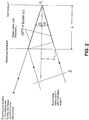
- FIG. 2 depicted in Fig. 2 where an illuminating plane wave, ⁇ , impinges on a Fizeau interferometer of length, L , with an inclination angle, ⁇ .
- the Fizeau interferometer is built from the reference surface, R, and the test surface, T, and the intervening space is filled with air.
- the front and back surfaces of the plates carrying the reference surface and the test surface, R and T, respectively, are omitted to simplify matters.
- the test surface T carries a point A, for which the oblique ray, which is the center ray for the imaging of point A, onto a CCD detector is shown.
- the CCD detector itself, as well as all the other optical elements comprising the interferometer, are shown in Fig. 5 , and will be discussed in further detail later.
- the phase-difference, ⁇ which is decisive for the final interference pattern on the detector, is a function of the optical path difference (OPD) within the Fizeau interferometer as well as of the wavelength of the light.
- OPD optical path difference
- the phase-difference, ⁇ is a function of the wavelength, ⁇ , the interferometer thickness, L , as well as of the inclination angle, ⁇ .
- the position and direction of the rays illuminating and imaging the point A through all the interferometer optics changes with the inclination angle, ⁇ . If ⁇ is changed during the integration time of one camera frame, the influence of the micro roughness on all optical parts, with the exception of the test piece itself, changes rapidly and cancels out in the time-average.
- Fig. 5 is a diagrammatic elevational view of an embodiment of the invention designated generally as system 10.
- System 10 comprises a light source S, a point source such as a laser, collimation and imaging optics comprising collimation lens 20 and an objective or ocular lens 40, a CCD or other equivalent detector 50, and a Fizeau interferometer 30 where object points A and B on a test surface are imaged into image points A' and B' on the detector 50.
- a and B are located at a test surface plane T, and A' and B' are located at the CCD detector plane.
- the upper and lower sketches of Fig. 5 show the light source S in different positions both of which are distant or offset in their entirety with respect to the optical axis, OA.
- the light source S is shifted from the optical axis to an off-axis position below the optical axis, and in the lower sketch by the same amount, but above the optical axis.
- the OPD is identical in both cases with the different object-points A and B having the same OPD as well for reasons elaborated on above.
- the light irradiating the test surface T is collimated, and the reflected light traveling between the collimating lens 20 and the objective lens 40 is also collimated. Notice that for this type of imaging, even though only the center rays (oblique rays) are shown, all rays contributing to an image point have the same optical path length between object point and image point. In the case of an afocal system, even the optical path length between different object points in the same object plane have equal path lengths.
- means for directing radiation onto an object being studied in an interferometer from different locations that are distant with respect to an optical axis such that radiation from the locations is incident to the same points on the object along optical paths having substantially identical optical path differences in the interferometer to generate interfering wavefronts; the radiation from each location generating optical interferometric beams in which the properties of interest in the object, such as the wavefront it returns or its topography, are encoded as substantially identical phase information while the field position of phase information corresponding to artifacts differs because of different parallax perspectives from each of the different locations.
- a rotating point may also be used.
- To form a ring source use may be made of a point source with a bulk optic axicon or its diffractive equivalent. Combinations of such sources may also be beneficially used.
- Fig. 5 shows, that for different locations of the point source S, the whole course of the rays through the optical system is different. That is exactly the desired effect, since this is the way to overcome the coherent artifacts by effectively using an extended aperture.
- This property preserves the spatial coherence with a single ring shaped source, a rotating point source, provides an unequal path interferometer, such as a Fizeau interferometer, having high imaging quality for very fine object details as well as the very good resolution of very small surface height variations that can be achieved with equal path interferometers such as Michelson or Mirau type interferometers.
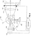
- Fig. 6 is a diagrammatic elevational view of an embodiment of the invention designated generally as system 100.
- system 100 is a Fizeau interferometer that utilizes a PZT, a rotatable beam splitter, and rotating wedge to act in concert as a double phase shifting means as well as a "virtually extended source" in the measurement of a transparent plane parallel plate.
- the transparent plate to be measured is shown at 102 with a reference surface at 104.
- a source 106 passes through a rotating wedge 108 to be imaged on a rotatable beam splitter 112 and thereafter onto the plate 102 via imaging optics comprising converging lens 110 and collimator lens 118.
- a well-known rotating device 114 is responsible for selectively rotating beam splitter 112 under the control of a computer 124. Reflected light beams from the reference surface 104 and test surface 102 are imaged onto a suitable sensor 122 via collimator lens 118 and objective or ocular lens 120. The output of the sensor 122 is fed to the computer 124 for well-known phase and subsequent numerical analysis along with any image processing requirements for display and metrology purposes. Computer 124 also controls a motor 109 connected to wedge 108 for selectively rotating it, and also connects with a PZT 126 that selectively drives reference 104 to modulate it along the optical axis, OA.
- three coherent waves will interfere in system 100.
- the first is the portion of the illuminating plane wave reflected from the reference surface 104
- the second is the portion reflected from the front surface of the transparent plate 102
- the third is the portion reflected from the back surface of the transparent plate 102. Because either the front surface or the back surface is to be measured at one time, the presence of the remaining reflection acts as a disturbance, and in this special case, the disturbance is of the same order of magnitude as the desired wave.
- the influence of this unwanted third wave can be cancelled by introducing two independent phase shifts using the components of system 100.
- the last row in the table shows the lateral shift of the point source off the optical axis that would be necessary if a collimator lens with a focal length of 500 mm were used.
- a change in the inclination angle is easily produced in system 100 by changing the angle of the beam splitter 112 in Fig. 6 .
- the beam splitter 112 is mounted on a rotation-device 114 that is controlled by the computer 124, which also acquires the detector frames for the measurement.
- the second independent phase shift which is necessary for full control in the general case, is performed by the conventional PZT-device 126, shifting the reference surface 104 along the optical axis, OA.
- a rotating glass wedge 108 is shown in addition to the rotatable beam splitter 112 in addition to the rotatable beam splitter 112, a rotating glass wedge 108 is shown. Wedge 108 can be used with the beam-splitter 112 to further reduce coherent noise, as described before.
- the virtual orbits of the light source around the optical axis may describe ellipses, where one axis is given by the wedge-angle and is fixed, and the other axis of the ellipse is defined by the angular movement of the beam splitter 112 and can be controlled to fit the needs for suppressing the unwanted influence of one of the surfaces of the parallel plate.
- FIG. 7A a diagrammatic elevational view of another embodiment of the invention appears designated generally as system 200.
- system 200 two wedges in series, controlled by dedicated electronics or a computer, describe a multiple of patterns in the focal plane of a lens, e.g., circles with different diameters, ellipses with different minor and major axes, and lines of different orientations, all of which can be driven synchronously together and also synchronized with the camera frames while at the same time having their angular phase relation altered, also under control of the computer 216.
- system 200 comprises a light bundle 202 provided in any well-known manner, a pair of series mounted rotatable wedges 204 and 206 driven, respectively, by motors 212 and 214, both under the control of a computer 216 or other suitable control electronics.
- Light bundle 202 is selectively deviated by wedges 204 and 206 in accordance with their relative positions and angular speed of rotation, and is subsequently focused to a focal plane 210 via a lens system 208 that is diagrammatically shown.
- the image of the light bundle 202 in the focal plane 210 may now be used as the extended interferometer source to suppress artifacts while enhancing signal to noise performance in the interferogram.
- wedges 204 and 206 have the same wedge angle, they can be adjusted to cancel their effect, i.e., the focused point remains on the optical axis while the wedges are spinning synchronously. But if the wedges are rotated by 180° with respect to each other, their effects are added and the point describes a circle with a maximal radius. Intermediate positions of the relative rotation of the wedges 104 and 106 can operate to provide any radius r between zero and r max . Well defined, discrete radii are needed for the case of canceling out one wave and at the same time reducing coherent noise. It should also be apparent that pairs of reflective scanning mirrors rotatable about mutually perpendicular axes can be used in system 200 for this purpose or in system 100 of Fig. 6 for similar reasons. In the foregoing manner, phase shifting is managed by changing the phase of the rotation of motors 212 and 214 with respect to one another.
- Fig. 7B is an embodiment employing two mirrors in a row by which phase-shifting can be managed by changing the phase of the rotation of motors on which the mirrors are mounted.
- mirrors 205 and 209 are mounted for rotation on motors 207 and 211, respectively.
- the surfaces of the mirrors 205 and 209 are made to be not perpendicular to the optical axis (mirror "wedges").
- an incoming beam 203 follows a cone like output as in the case of the wedges above and is dependent on the relative phase of the motors 207 and 209. This effect can be cancelled or added by the two mirrors in a row, so the mirrors are fully equivalent to the wedges in transmission.
- Fig. 7C is a diagrammatic elevational view of yet another embodiment of the invention in which two acousto-optic modulators (AOMs) in series are selectively modulated to provide desired illumination.
- this embodiment is diagrammatically shown as a system 300 which comprises an input beam 302 that is brought to focus on the optical axis by a converging lens 304. Beyond the focus following converging lens 304, the beam 302 diverges and then is collimated by collimating lens 306 after which it is fed to a pair of series arranged acousto-optic modulators 308 and 310.
- beam 302 Upon emerging from acousto-optic modulator 310, beam 302 is refocused by an objective lens 312 to focal plane 314 after which it re-expands to serve as the input to a collimator lens 316.
- the output of collimator lens 316 then serves as the illumination or irradiation source for a downstream interferometer as before.
- Acousto-optic modulators, 308 and 310 are arranged in series so that one of them deflects the transmitted beam in the zy-plane, and the other in the zx-plane.
- a circle with radius, r is described at the focal plane 314 of the collimator lens 316. This radius r can be changed by the amplitude A of the modulation of the AOMs.
- T the time - constant
- the amplitude can be changed and within one frame rate lasting the total exposure time for the CCD-camera of T c ms, m different values for the amplitude A can be realized.
- acousto-optic modulators 308 and 310 may be replaced with electro-optic modulators to provide similar functionality.
- a convergent beam passing through an axicon or diffractive equivalent can provide an elegant solution as already mentioned. If the axicon or diffractive equivalent is shifted axially, the diameter of the ring is changed.
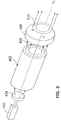
- FIG. 8 shows multimode fiber 400 excited by a laser source 402 that is imaged onto the fiber's entrance facet via a lens system 404.
- Lens system 404 may be designed to control the angle of incidence and numerical aperture match to multimode fiber 400 so as to excite it in a well-known manner to generate a ring of illumination 406 that can thereafter be further controlled by following optics 408 to provide, for example, a collimated ring 410.
- the diameter of ring 406 may be selectively changed by varying, for example, the conditions under which the laser beam enters multimode fiber 400.
- interferometers may easily be altered to handle spherical surfaces as well by appropriately designing the lens responsible for controlling the shape of the incoming wavefront impinging on the object and reference surfaces.
- the thickness of a thin ring may be readily determined with the use of Equation 1a and calculating when the phase shift created between the inner and outer diameters of the ring would exceed 180°, thus resulting in destructive interference. Consequently, the thickness should be made such that this phase shift is less than 180° by an amount that is consistent with the contrast requirements of the measurements being made.
- the nominal diameter of the smallest ring may be determined empirically and in general depends on wavelength, interferometer length, and the proximity of the source of the artifact to the surface under test.
- ring diameters of 0.25mm to 1mm were found adequate to suppress the typical artifacts, principally from the vicinity of the beamsplitter in a breadboard interferometer, which was a based on the GPI Product of Zygo Corporation, Middlefield, CT, US. From these results, a representative ring diameter of 1mm has been found adequate, since this diameter did not impact on the design of a commercial collimator design used in the breadboard.
- Both image points are located opposite to the object points on the other side of the optical axis of the lens. They coincide because the magnification, ⁇ , of the imaging of a spherical mirror is independent of its radius of curvature when the object point is in the near vicinity of the center point of the sphere.
- Very weak aberrations are introduced by the small displacement from the true center point of the spherical surfaces, and these aberrations depend on the radii of curvature of the two spheres.
- the result of this test configuration is a so-called rotational shear interferogram, where the two interfering wavefronts are rotated by 180° with respect to each other. That is the wanted effect for this third configuration, to supply the necessary information for the absolute evaluation of the test-surface errors in connection with the other two measurements.
- FIG. 10 shows non-normally configured cavity with a Fizeau lens (transmission sphere) 500 with an inclined incident plane wavefront 1a1b and resulting wavefronts 1a'1b' from reflection of the reference surface 502 and 1a"1b" from reflection from a cat's eye mirror designated generally as 504. Note the angle 2 ⁇ between the two wavefronts leaving the lens.
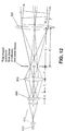
- Fig. 12 there are a number of ways by which two inclined coherent wavefronts can be produced.
- Fig. 12 the coherent plane wavefront from a laser 510 is expanded by a beam expander 512 and then impinges on a rotating phase-grating 516.
- grating 516 is shown in Fig. 13 , all even diffraction orders will be very weak, giving rise to about 40% of the energy within the first and minus first order.
- Grating 516 is located behind an afocal system consisting of an "ocular lens" 518 with focal length f1 and a "collimator lens” 520 with focal length f2, known as a "Kepler telescope".
- a physical aperture glass-plate with a chromium layer forming a ring-shaped aperture
- Fig. 12 It is possible to image the diffraction grating 516 with this configuration.
- the image is located near the collimator lens 520; but if the distance z 1 is changed, the location of image of grating 516 is also changed and another location can be chosen, for instance the location at the reference surface of the Fizeau-lens, see Fig. 11 .
- This change in distance of z 1 does not alter the location of the ring-shaped aperture behind the ocular lens 518.
- the diffraction grating 516 again, is shown in Fig. 13 .
- FIG. 14 shows prismatic elements 522 and 524 attached to the output facets of a beamsplitter 526 to generate two oppositely located point sources that travel over identical optical path lengths.
- Fig. 15 shows yet another embodiment for generating two coherent plane wavefronts tilted symmetrical to the optical axis by means of using a rotational shearing interferometer.
- a rotating grating must be adjusted very precisely to introduce no phase-changes between the two diffraction orders used during rotation.
- the holographic element is a flip-in device which is not critical to adjust and the ground glass need not be adjusted laterally at all; its axis of rotation being arbitrary.
- a rotational shearing interferometer as a device that is able to produce, in addition, an identical copy of the wavefront, but rotated by 180° with respect to the original position.
- a laser 530 undergoes beam expansion via expander 532.
- the expanded beam is received by a holographic device 530 to produce a ring, which is received by a rotating ground glass 536 to make all points of the ring incoherent to each other.
- a rotational shearing interferometer 538 (RSI) produces two identical copies (same dynamic of phase changes) of the wavefront from the rotating ground glass 536, but rotated with respect to each other by 180°.
- a beam expander 540 comprising an ocular and a collimator lens (neither shown) enlarges the two tilted wavefronts.
- a beamsplitter 542 is provided in the beam expander for directing returning wavefronts to a CCD device (not shown).
- Two coherent plane tilted wavefronts 542 and 544 emerge from the beam expander 540 and enter a transmission sphere 546 with a confocal reference surface.
- the cat's eye mirror is designated at 548.
- both partners for the interference stem from different illumination wavefronts. That means the device that produced A 0 and A 180 may introduce different aberrations into these wavefronts. Therefore, it is necessary to re-investigate the procedure for absolutely measuring the wavefront of the test surface with the inclusion of A 0 and A 180 .
- W ⁇ 2 A ⁇ 0 + 2 L 180 + R 180 ⁇ A ⁇ 0 + 2 L 180 + T 0 + A ⁇ 180 + 2 L 180 + R 180 ⁇ A ⁇ 180 + 2 L 180 + T 0
- W ⁇ 3 A ⁇ 0 + 2 L 180 + R 180 ⁇ A 180 + L 0 + L 180 + A ⁇ 180 + 2 L 180 + R 180 ⁇ A 0 + L 0 + L 180
- T 1 4 W 3 + W ⁇ 3 ⁇ W 1 ⁇ W ⁇ 2
- the rotational shearing interferometer 538 may be realized in a number of ways.
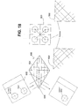
- Fig. 17 illustrates a rotational shear interferometer in which Dove-prisms are oppositely rotated by 45° to generate two symmetrically located points.
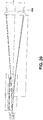
- Figs. 18 and 19 Another solution for this task is shown in Figs. 18 and 19 , where a new type of rotational shear interferometer is shown, which is made of only three pieces of glass. It is a symmetrical design, somewhat similar to a Sagnac interferometer, but it is not really cyclic. Therefore, the errors introduced in the two legs may differ and do not automatically cancel.
- the bundle enters a Koester's prism is split into two halves and both are then reflected by a prism 604 made as a four-sided pyramid.
- the beams now leave their original plane; that is, where a rotation of both beams by 90° is introduced.
- the final relative rotation of the beams is the sum of those two rotations, i.e., 180°.
- each of the beams enters the Koester's prism 602 again, and they are finally recombined by a beamsplitter. They leave the prism 604 at another height and on the other side of the Koester's prism 602.
- a focusing lens 610 converges an input beam to a holographic element 612 to produce a ring.
- the ring then encounters a rotating diffuser 614 located at the focus of the collimator lens 608, and then enters the Koester's prism 602, after which it is treated as described above. It is obvious from Fig. 19 that a change in the direction of the incident bundle by 60° is encountered; but the change in height is not visible in Fig. 19 .
- Another possible way to realize two wavefronts with pairs of coherent sources with the same phase on opposite sides with respect to the optical axis involves the use of a scatterplate.
- the basic procedure for making a scatterplate is to expose a photographic plate to a speckle pattern produced by illuminating a piece of ground glass with a laser beam. Since the scatterplate must have inversion symmetry, two superimposed exposures to the speckle pattern must be made, where the plate is rotated 180° between the exposures.
- the solid angle subtended by the illuminated piece of ground glass, as viewed from the photographic plate should be at least as large as the solid angle of the surface under test viewed from the scatterplate during the test.
- the photographic plate After development, the photographic plate should be bleached to yield a phase scatterplate.
- the exposure, development, and bleaching should be controlled so that the scatterplate scatters 10% to 20% of the incident light.
- the scatterplate should be illuminated by the ground glass for production with a numerical aperture larger than that used in the collimator lens, and the exposure, development and beaching should be done such that the highest amount of scattered light is reached, and the two exposures should be done in the original holder, which inherently contains a high precision bearing for rotation.
- the optical center coincides automatically with the mechanical center of the scatterplate.
- Fig. 21 To use the scatterplate, an arrangement as shown in Fig. 21 is made. The only alignment needs are to align the holder of the scatterplate 620 with respect to the optical axis, which is defined by the apex of the lens 624 and the symmetry center of the holographic device 622.
- FIG. 23c shows an impossible location for the rotation axis because it introduces a phase shift of 2 ⁇ between the coherent beams when the grating is rotated by 180°.
- Fig. 23d shows a case where there is a severe phase shift of 5 x 2 ⁇ where the axis of rotation is off by 2.5 lines of the grating from the optical axis.
- the useful interference systems here are washed out when the integration time is chosen to be equal to the time of one revolution of the grating.
- the invention is not restricted to the case of Fizeau interferometers, but can be applied with all other kinds of interferometers including, but not limited to, unequal path types such as the Mirau and Twyman-Green.
- the principle underlying the invention can equally be applied to the testing of spheres.
- use may be made of one or more beam steering mirrors driven by galvanometers or the like in place of rotating wedges.
Landscapes
- Physics & Mathematics (AREA)
- General Physics & Mathematics (AREA)
- Engineering & Computer Science (AREA)
- Automation & Control Theory (AREA)
- Optics & Photonics (AREA)
- Instruments For Measurement Of Length By Optical Means (AREA)
Description
- This invention in general relates to interferometric apparatus and methods and in particular to the construction and use of light sources by which coherent artifacts that would otherwise be present in an interferogram can be suppressed to improve the overall signal to noise ratio.
- Optical systems of all types are adversely affected by background light, ghost reflections, and/or unwanted light scattered from elements in an optical assembly, and many techniques have been developed (such as baffles and apertures) to limit the degree to which such undesired light reaches an image. If the optical system uses incoherent light, the background simply adds to the overall light level at the image. In photographic systems, such light may be characterized as veiling glare, which operates to reduce contrast in the final photograph. Another common example is the reduction in visibility an automobile driver experiences in viewing through a dirty windshield where scattering operates to generate an overall glare that reduces the contrast in the surrounding landscape.
- However, if the optical system uses coherent radiation (e.g., laser light), as is the case with many types of interferometers, scattered light can coherently interfere in the interferometric image to produce large amplitude light level changes with a spatial and/or temporal structure that can completely mask the desired interference pattern. The extreme sensitivity of these interferometers make them adversely affected by even the slightest background that can be produced by the smallest of imperfections in any practical system. Dust or tiny scratches on the optical surfaces of the system, or even variations in the antireflection coatings, are but a few examples of imperfections that can be problematic. Collectively, these flaws are often called optical artifacts, and when observed in coherent optical systems, are known as coherent artifacts.
- A commonly used commercial interferometer geometry is known as the Fizeau geometry. The Fizeau geometry has many advantages: the optical system is common path; it has a minimum number of optical components; and is highly manufacturable. However, the unequal path design forces the use of coherent light sources. Hence, light from all locations in the system optics and interferometer, including scattering from small surface defects such as scratches, pits or dust (or volume defects such as bubbles) can influence the interferogram. These defects act as light scattering centers, producing characteristic ring patterns called Newton rings or "Bulls-eye" patterns that can imprint onto the measured phase map, affecting the extracted surface topography. Even the spurious micro-roughness of good polished surfaces and antireflection coatings contribute to the micro-shape of the wavefronts in the interferometer, and since the wavefronts are no longer common path in such a lateral scale of roughness, they establish themselves in the final measured wavefronts.
- One common practice that is responsible for introducing artifacts is the use of commercially available optical components that have not been specifically designed for use in interferometer configurations and light sources with minimization of artifacts in mind yet possess other properties that make their use commercially attractive for economic reasons. Off-the-shelf lenses, for example, often possess desirable performance specifications in terms of aperture, field, focal length, and aberration control, but may have interior structure that, while suitable for other applications, introduce unwanted artifacts in interferometers.
- One well-known method for reducing the effects of coherent artifacts in interferometers is to use a spatially extended source, typically in the shape of a disk. However, the spatial coherence of the source is compromised with an extended source resulting in the production of visible interference fringes for only a limited range of interferometer lengths determined by the source diameter.
-
DE 42 33 336 A describes an interferometer intended to provide improved accuracy of measurement. The quantity and the direction of movement of an object are computed by a computer from the striped pattern images on four camera detectors. Next, a focus control signal is obtained from the computed value. The object to be measured is moved by a focus drive device until a point to be scanned is on the focus of an objective lens. For computing the shift, phase values are computed against respective camera pick cells for example by the use of four step evaluation algorithm used in the interferometer. Stripe frequency is directly proportional to induction of the phase value in each stripe period. A derivative is proportional to the movement and X value, and the sign of the derivative corresponds to the moving direction. -
US 6 031 612 A describes a method for determining, on an object having a surface, three-dimensional position information of a point on this surface. The method comprises: providing two sources of radiation separated by a distance, these sources being coherent with respect to one another; illuminating the specified point on the surface of the object with radiation from each of the sources; moving the sources relative to each other; detecting radiation scattered by the specified point on the surface of the object; and calculating position information in response to the movement of the sources and the detected radiation scattered by the specified point. -
US 3 958 884 A describes an interferometric apparatus comprising an optical assembly for simultaneously directing two mutually coherent light pencils at different respective angles of incidence towards a point on a surface under investigation and receiving reflected light pencils respectively produced by reflection of the two mutually coherent light pencils at that surface. The optical assembly also includes optical means for bringing the reflected light pencils at least partially into co-incidence with one another so that the reflected light pencils can interfere optically with one another in a manner which varies with variation in the distance of points on the surface from a reference plane. -
WO 01/20295 A2 -
US 5 995 224 A describes a geometrically-desensitized interferometer for profiling an object surface. This interferometer comprises: (A) a light generator; and (B) an optical assembly which is disposed between the light generator and the object surface, which includes a non-diffractive optical element and a diffractive optical device, and which is arranged to 1) divide light received from the light generator into first and second beams which a) propagate in two different directions, b) impinge upon the object surface at essentially the same location but at different incident angles, and c) then reflect off the object surface and 2) recombine the first and second beams propagating from the object surface to form an interference pattern representative of a profile of the object surface, wherein the first beam follows a first path through the optical assembly, this first path contacting both the non-diffractive optical element and the diffractive optical device, wherein the second beam follows a second path through the optical assembly, this second path contacting the non-diffractive optical element and avoiding the diffractive optical device, and wherein the first and second paths meet at the non-diffractive optical element. -
US 6 072 581 A describes a geometrically-desensitized interferometer generally similar to that described inUS 5 995 224 A above. However, inUS 6 072 581 A , the light generator is spaced from the test object surface in a Z direction, and interferometer also comprises an imaging device which is disposed on a common side of the optical assembly with the light generator and which has an aperture arranged to receive light transmitted through the optical assembly by the light generator and reflected back through the optical assembly by the test object surface. The test object surface lies in or closely adjacent to an optimum metrology plane in which the first and second reflected beams originate at the same location on the test object surface but at different incident angles. The optical assembly is configured to steer stray light beams away from the aperture of the imaging device while at least essentially minimizing phase offset. - Accordingly, this invention seeks to provide a new extended source geometry that does not suffer from the contrast degradation of conventional extended sources yet provides excellent suppression of unwanted interference from surfaces and objects far from the object of interest to improve the accuracy and resolution of surface profiling using phase-shifting interferometry.
- This invention also seeks to provide a convenient way to modulate the phase of the interference, further benefiting particular applications developed for phase shifting interferometry.
- This invention also seeks to provide a way to suppress interference from surfaces parallel to the surface of interest, such as in the measurement of one surface of parallel flats.
- This invention also seeks to provide a source for reducing the effects of artifacts in interferometers using off-the-shelf components.
- This invention also seeks to provide a source for use in reducing artifacts in unequal path length interferometers such as, for example, Fizeau, Mirau, and Twyman-Green types.
- Finally, this invention seeks to provide a source for use in reducing artifacts in interferometers in which retroreflective elements such as cat's eyes form part of the interferometer cavity.
- Accordingly, this invention provides an interferometric apparatus having an optical axis and comprising:
- means for locating an object to be measured along the optical axis;
- a detector;
- an optical arrangement adapted to at least in part cooperate with the object to form an interferometer cavity and facilitate the generation of interfering wavefronts in which phase information about the object is encoded and imaged on to the detector; and
- radiation directing means for directing radiation onto the object to be measured. The apparatus is characterized in that the radiation directing means directs radiation at the object from at least two different off-axis points of illumination that are distant from the optical axis such that radiation from each of the different off-axis points of illumination is incident to the same points on the object along optical paths having identical optical path differences within the interferometer cavity to generate interfering wavefronts corresponding to each of the off-axis points of illumination, each wavefront containing substantially identical phase information about the object and being added together incoherently at the same point on the detector, each of the interfering wavefronts corresponding to each of the different off-axis points of illumination also including unwanted phase information that is averaged on the detector.
- This invention also provides an interferometric method comprising:
- locating an object to be measured along an optical axis;
- providing a detector;
- arranging optical components adapted to at least in part cooperate with the object to form an interferometer cavity and facilitate the generation of interfering wavefronts in which phase information about the object is encoded and imaged on to the detector; and
- directing radiation onto the object to be measured.
- Generally, the present invention relates to interferometric apparatus and methods for preserving fringe contrast in interferograms while suppressing coherent artifacts that would otherwise be present in the interferogram because of coherent superposition of unwanted radiation generated in the interferometer. Several different embodiments of the invention achieve this result through the use of illumination and interferogrammetric imaging architectures that generate individual interferograms containing the same phase information of preselected characteristics or properties of a test surface (e.g., wavefront, topography) from the perspective of different off-axis points of illumination in an interferometer. Such individual interferograms are combined to preserve fringe contrast while at the same time arranging for artifacts to exist at different field locations so that their contribution in the combined interferogram is diluted. Thus, the same phase differences in the interferometer, corresponding to specific locations on a test surface, are mapped through optics along different light paths.
- The apparatus of the invention may comprise an illumination mechanism producing an extended source structure, e.g., in the shape of a thin ring of nominally constant radius that is nominally centered around an interferometer system optical axis. The ring defines the interferometer source plane. The interferometer system projects the source illumination into an interferometer where the illumination is split into two separate illumination paths. The illumination from the two separate paths is recombined after exiting the interferometer and is projected onto a detector at an image plane where the interferogram is detected and subsequently analyzed.
- Alternatively, the apparatus of the invention may use a point source moved in a source plane in a manner so as to describe a circle of constant radius about the optical axis in less than the time it takes to expose one detector frame. In this way a "virtual" ring shaped source is established.
- The apparatus may also use a source comprising at least one pair of oppositely spaced mutually coherent points of illumination simultaneously provide a pair of oppositely inclined plane wavefronts for use in reducing coherent artifacts in interferometers having retroreflective elements, such as cat's eyes, in the cavity.
- In yet another embodiment, the radius of the source ring (produced directly or virtually) is changed dynamically, in either continuous or stepwise fashion, while the detector senses the interferogram. As the ring radius changes, the phase of the interferogram changes in a predictable way, providing the ability to modulate the interferometric phase in a manner required by phase-shifting or phase stepping interferometry applications.
- The structure, operation, and methodology of the invention, together with other advantages thereof, may best be understood by reading the detailed description in conjunction with the drawings in which each part has an assigned numeral that identifies it wherever it appears in the various drawings and wherein:
-
Fig. 1 is a diagrammatic view for estimating the difference in optical path distance (OPD) between interferograms produced by an on-axis test point with illumination from a source point on the edge of a source disk of diameter, d, and a source point at the center of the disk (on-axis). The on-axis source point path produces the solid on-axis (covered twice) line, while the off-axis source point produces the path shown by the dotted line; -
Fig. 2 is a diagrammatic illustration showing how the OPD in a Fizeau interferometer filled with air gets smaller as the angle of incidence, α, increases where the thickness of the air gap is L; -
Fig. 3 is similar toFig. 2 where the Fizeau interferometer is filled with glass of index n (plane parallel transparent plate) instead of air as inFig. 2 ; -
Fig. 4 is a diagrammatic illustration showing the relationship among the image height, field-angle, and focal length of a lens; -
Fig. 5 is a diagrammatic elevational view of an embodiment of the invention showing a light source S, collimation and imaging optics, CCD detector, and Fizeau interferometer where object points A and B are imaged into image points A' and B'; A and B being located at a test surface plane T, and A' and B' being located at the CCD detector plane where the light source is shown in different positions with respect to the optical axis, OA. In the upper sketch, it is shifted from the axis to an off-axis distant position that is below the optical axis, and in the lower sketch by the same amount, but above the optical axis. The OPD is identical in both cases with the different object-points A and B having the same OPD as well; -
Fig. 6 is a diagrammatic elevational view of an embodiment of the invention in which a PZT, a rotatable beam splitter, and rotating wedge act as a double phase shifting means as well as a virtually extended source; -
Fig. 7A is a diagrammatic elevational view of another embodiment of the invention in which two wedges in series, controlled by special electronics or a computer, describe a multiple of patterns in the focal plane of a lens, e.g., circles with different diameters, ellipses with different small and long axes, lines of different orientations; -
Fig. 7B is a diagrammatic elevational view of another embodiment of the invention in which two mirrors provide results equivalent to those of the embodiment ofFig. 7A ; -
Fig. 7C is a diagrammatic elevational view of yet another embodiment of the invention in which two acousto-optic modulators (AOMs) in series are selectively modulated to provide desired illumination; -
Fig. 8 is a diagrammatic perspective view of an embodiment of an inventive illumination system employing a multimode fiber excited by a source so that the output modal pattern of the fiber is in the form of a circular ring whose diameter may be changed by altering the angle of incidence of the excitation source; -
Fig. 9 , comprisingsubfigures 9a-9d, shows various inventive source patterns employing solid and virtual single and double ring possibilities; -
Fig. 10 is a diagrammatic elevational view illustrating the resulting wavefronts returned from a Fizeau interferometer having a retroreflective element in its cavity when illuminated with an inclined plane wavefront; -
Fig. 11 is a diagrammatic elevational view illustrating the resulting wavefronts returned form the Fizeau interferometer ofFig. 10 when illuminated with a pair of oppositely inclined plane wavefronts; -
Fig. 12 is an embodiment of the invention in which a rotating grating generates inclined wavefronts of the type illustrated inFig. 11 ; -
Fig. 13 is a diagrammatic elevational view of a phase grating used in the embodiment ofFig. 12 ; -
Fig. 14 is a diagrammatic elevational view of an alternate embodiment for providing oppositely inclined wavefronts through the use of a beam splitter and associated; -
Fig. 15 is a diagrammatic elevational view of an interferometer system of the invention employing a rotational shearing interferometer; -
Figs. 16A, 16B, and 16C are diagrammatic representations used to introduce the meaning of various terms used in mathematical relationships appearing in the detailed description; -
Fig. 17 is a diagrammatic elevational view of another alternate embodiment for providing oppositely inclined wavefronts through the use of a rotational shear interferometer implemented with a pair of Dove prisms; -
Fig. 18 is a diagrammatic elevational view of construction details of Koester's prism and a quadratic pyramid as a rotational shear interferometer; -
Fig. 19 is a diagrammatic elevational view of an embodiment of a rotational shear interferometer having 180° of rotational shear with a Koester's prism together with a quadratic pyramid as shown inFig. 18 ; -
Fig. 20 is a diagrammatic elevational view of the unfolded light path through Koester's prism and quadratic pyramid ofFig. 18 ; -
Fig. 21 is a diagrammatic elevational view of a very simple arrangement producing two identical wavefronts rotated by 180° with respect to each other through the use of a special phase-scatter-plate which is mounted and rotated in a high precision bearing; -
Fig. 22 is a diagrammatic front view showing a pattern of illumination points produced simultaneously by a holographic diffraction element;. and -
Figs. 23a-23d are diagrammatic views illustrating good and poor practices for placement of the axis of rotation of the grating used in invention. - The present invention generally relates to interferometric apparatus and methods for preserving fringe contrast in interferograms while suppressing coherent artifacts that would otherwise be present in the interferogram because of coherent superposition of unwanted radiation generated in the interferometer. Several different embodiments of the invention achieve this result through the use of illumination and interferogrammetric imaging architectures that generate individual interferograms of test surface properties of interest from the perspective of different points of illumination that all are distant from its optical axis, i.e. off-axis. These individual interferograms are then combined to preserve fringe contrast in an integral interferogram while at the same time arranging for artifacts to exist at different field locations so that the contribution of artifacts in the combined interferogram is diluted, smeared, or averaged out. Thus, the same phase differences in the interferometer corresponding to specific locations on a test surface are mapped through optics along different light paths. The invention includes other features for phase modulation that make it amenable for use with phase shifting and stepping interferometry techniques.
- To understand the operation of the invention, it will be useful to first examine the nature of the source it employs to generate individual interferograms and how the phase information contained in each of those individual interferograms is substantially identical so that they can be beneficially combined while suppressing artifacts.
- Any extended source can be thought of as a large number of physically separate point sources. From the perspective of each source point, the position of an artifact shifts in the field due to parallax. Therefore, a properly imaged final interferogrammetric image can be made to be the sum of images from individual interferograms corresponding to all the point sources, effectively smearing out the interference patterns stemming from the artifact. However, unlike typical extended sources, the source of the invention maintains good fringe contrast by assuring that the interferograms produced by each source point are identical (i.e., their optical path differences (OPD) are the same).
- To understand the difference between the inventive source and typical extended sources, it is useful to examine the properties of a typical disk source centered on the optical axis. Such a disk source does not fulfill the requirement met by the invention since source points at different positions along a radius of the disk produce different interferograms. This can be easily demonstrated by comparing the OPDs for a particular position on the test surface from a source point situated at the center of the disk (on-axis) and a source point on the edge of the disk. Assume for convenience an interferometer with a Fizeau geometry as shown in
Fig. 1 , a circular extended source of diameter d, an interferometer length L and collimator focal length f. For this fixed configuration, it can be shown that the difference, Δ, in the OPDs is given approximately by:
Fig. 2 explains in detail why this is so and under what conditions this contrast reduction can be minimized. - Considering now the optical system depicted in
Fig. 2 where an illuminating plane wave, Σ, impinges on a Fizeau interferometer of length, L, with an inclination angle, α. The Fizeau interferometer is built from the reference surface, R, and the test surface, T, and the intervening space is filled with air. The front and back surfaces of the plates carrying the reference surface and the test surface, R and T, respectively, are omitted to simplify matters. The test surface T carries a point A, for which the oblique ray, which is the center ray for the imaging of point A, onto a CCD detector is shown. The CCD detector itself, as well as all the other optical elements comprising the interferometer, are shown inFig. 5 , and will be discussed in further detail later. - It can be seen from
Figs. 2 andFig. 5 , that different rays from the illuminating plane wave Σ, which originally have a lateral distance of 2h at the reference surface, will combine after reflection from the reference surface and the test surface, respectively, to finally give rise to the wanted interference effect on the detector. It should be noted that these two rays, after reflection on the two surfaces (inbound rays) are common path through the whole instrument until the detector, as long as the two surfaces are adjusted to be parallel. Ideally, all imperfections of the optical surfaces therefore have the same influence on both rays and do not show in the interference pattern. This fortunate behavior is not true if the rays deviate from each other by a very slight amount, which occurs when the interferometer is not perfectly nulled or the test piece has some deviation from planeness. This is the general case, and for this case, the invention provides an improvement in the quality of measurement. - The phase-difference, ϕ, which is decisive for the final interference pattern on the detector, is a function of the optical path difference (OPD) within the Fizeau interferometer as well as of the wavelength of the light. The OPD is defined by the distance, L, of the two surfaces comprising the interferometer, as well as the inclination angle, α, of the illuminating beam. The following holds:

- In total, the phase-difference, ϕ, is a function of the wavelength, λ, the interferometer thickness, L, as well as of the inclination angle, α. The position and direction of the rays illuminating and imaging the point A through all the interferometer optics changes with the inclination angle, α. If α is changed during the integration time of one camera frame, the influence of the micro roughness on all optical parts, with the exception of the test piece itself, changes rapidly and cancels out in the time-average. To have ϕ remain stationary while changing the inclination angle, α, one can compensate either by adapting L or λ, as can be deduced from (1b) by a Taylor series expansion:

- Eq. (2) is fulfilled under the condition:


- Eq. (3) can be fulfilled by


- If α is changed from 0 to α 1, then L should be changed from L 0 to L 1 according to:


- From the definition of focal length of a collimator by Gauss (see
Fig. 4 ), it follows that:


Fig. 5 . The effect is described by cos(α), which is an even function. The same is true for Eqs. (10) and (11), where y is squared and therefore both sides on either side of the optical axis are equivalent for the location of the point source. - Having described several of the fundamental principles by which the invention operates, reference will now be made to the apparatus of
Fig. 5 in more detail. -
Fig. 5 is a diagrammatic elevational view of an embodiment of the invention designated generally as system 10. System 10 comprises a light source S, a point source such as a laser, collimation and imaging optics comprising collimation lens 20 and an objective orocular lens 40, a CCD or other equivalent detector 50, and a Fizeau interferometer 30 where object points A and B on a test surface are imaged into image points A' and B' on the detector 50. A and B are located at a test surface plane T, and A' and B' are located at the CCD detector plane. The upper and lower sketches ofFig. 5 show the light source S in different positions both of which are distant or offset in their entirety with respect to the optical axis, OA. In the upper sketch, the light source S is shifted from the optical axis to an off-axis position below the optical axis, and in the lower sketch by the same amount, but above the optical axis. The OPD is identical in both cases with the different object-points A and B having the same OPD as well for reasons elaborated on above. The light irradiating the test surface T is collimated, and the reflected light traveling between the collimating lens 20 and theobjective lens 40 is also collimated. Notice that for this type of imaging, even though only the center rays (oblique rays) are shown, all rays contributing to an image point have the same optical path length between object point and image point. In the case of an afocal system, even the optical path length between different object points in the same object plane have equal path lengths. - It should be apparent from studying
Fig. 5 that the necessary compensation is independent of the sign of y, where at the upper part ofFig. 5 , the location for the point source S is below the optical axis and in the lower part ofFig. 5 , the location for the point source S is above the optical axis. In both cases the OPD in the interferometer is the same. - Another important fact that should also be apparent from the upper part of
Fig. 5 is that, if the two surfaces comprising the Fizeau interferometer 30 are exactly parallel, then no "fringes" appear on the CCD-camera. Two points A and B are considered in the upper part ofFig. 5 , and both have exactly the same OPD. In other words: the OPD does not change if point B is shifted to the position of point A. Therefore both lay on the "same interference fringe", which is infinitely wide in this case. The same is true for the other coordinate x, which is not shown inFig. 5 . This can be deduced by considering that the plane wavefront impinging on the interferometer is perpendicular to the surfaces of the interferometer and therefore any point "above" A (above the plane of the sketch), or below A, has the same OPD as A. Therefore, what holds for point A holds true for the whole surface of T. It is now clear that the location of the point source S may describe a circle with radius r = |y| without changing the OPD of the interferometer as a whole. Any of these locations will contribute to the same, stationary interference pattern in an incoherent, but constructive, way. Therefore, all of these patterns can be accumulated on a CCD-chip during the exposure time for one frame without degrading the interference contrast or integrated by combining a series of frames by accumulating them in an adding buffer, or the like. - In the foregoing manner, means have been provided for directing radiation onto an object being studied in an interferometer from different locations that are distant with respect to an optical axis such that radiation from the locations is incident to the same points on the object along optical paths having substantially identical optical path differences in the interferometer to generate interfering wavefronts; the radiation from each location generating optical interferometric beams in which the properties of interest in the object, such as the wavefront it returns or its topography, are encoded as substantially identical phase information while the field position of phase information corresponding to artifacts differs because of different parallax perspectives from each of the different locations.
- A rotating point may also be used. To form a ring source, use may be made of a point source with a bulk optic axicon or its diffractive equivalent. Combinations of such sources may also be beneficially used.
-
Fig. 5 shows, that for different locations of the point source S, the whole course of the rays through the optical system is different. That is exactly the desired effect, since this is the way to overcome the coherent artifacts by effectively using an extended aperture. This property, along with the various other apparatus and methods to be described, preserves the spatial coherence with a single ring shaped source, a rotating point source, provides an unequal path interferometer, such as a Fizeau interferometer, having high imaging quality for very fine object details as well as the very good resolution of very small surface height variations that can be achieved with equal path interferometers such as Michelson or Mirau type interferometers. - Until now, only the suppression of coherent noise was discussed. But, it is also possible, by varying the distance y of the point source S and simultaneously adjusting the OPD, to suppress the interference from an unwanted third surface within a "double" Fizeau interferometer. This will be discussed with reference to
Fig. 6 . -
Fig. 6 is a diagrammatic elevational view of an embodiment of the invention designated generally assystem 100. Generally,system 100 is a Fizeau interferometer that utilizes a PZT, a rotatable beam splitter, and rotating wedge to act in concert as a double phase shifting means as well as a "virtually extended source" in the measurement of a transparent plane parallel plate. The transparent plate to be measured is shown at 102 with a reference surface at 104. Asource 106 passes through arotating wedge 108 to be imaged on arotatable beam splitter 112 and thereafter onto theplate 102 via imaging optics comprising converginglens 110 andcollimator lens 118. A well-knownrotating device 114 is responsible for selectively rotatingbeam splitter 112 under the control of acomputer 124. Reflected light beams from thereference surface 104 andtest surface 102 are imaged onto asuitable sensor 122 viacollimator lens 118 and objective orocular lens 120. The output of thesensor 122 is fed to thecomputer 124 for well-known phase and subsequent numerical analysis along with any image processing requirements for display and metrology purposes.Computer 124 also controls amotor 109 connected to wedge 108 for selectively rotating it, and also connects with aPZT 126 that selectively drivesreference 104 to modulate it along the optical axis, OA. - As shown, three coherent waves will interfere in
system 100. The first is the portion of the illuminating plane wave reflected from thereference surface 104, the second is the portion reflected from the front surface of thetransparent plate 102, the third is the portion reflected from the back surface of thetransparent plate 102. Because either the front surface or the back surface is to be measured at one time, the presence of the remaining reflection acts as a disturbance, and in this special case, the disturbance is of the same order of magnitude as the desired wave. The influence of this unwanted third wave can be cancelled by introducing two independent phase shifts using the components ofsystem 100. Since at a solid plane parallel plate, it is not possible to change the relative phase of the two reflections of the front and back-surface by physical motion of one of the surfaces with respect to the other, a change in the illuminating wavelength can give the necessary degree of freedom needed to discriminate between the reflections in the final measured phase-map. The same is possible here, but the change in wavelength is now substituted with a change in the inclination angle α of the plane wave illuminating the Fizeau "double" interferometer. - Reference is now made to
Fig. 3 which shows that this inclination angle gives rise to a change in the OPD of a solid glass plate with thickness, L, and index of refraction, n, of:
- For a glass-plate, for example, of L =5mm with an index of refraction of n=1.5, α has to take on the following tabulated values for adjacent changes of the OPD of λ/2, (λ=633nm):
0 * λ/2 1 * λ/2 2 * λ/2 3 * λ/2 4 * λ/2 5 * λ/2 6 * λ/2 α [°] 0.000 0.558 0.790 0.967 1.117 1.248 1.368 y [mm] 0.000 4.872 6.890 8.439 9.745 10.895 11.935 - The last row in the table shows the lateral shift of the point source off the optical axis that would be necessary if a collimator lens with a focal length of 500 mm were used.
- A change in the inclination angle is easily produced in
system 100 by changing the angle of thebeam splitter 112 inFig. 6 . Thebeam splitter 112 is mounted on a rotation-device 114 that is controlled by thecomputer 124, which also acquires the detector frames for the measurement. The second independent phase shift, which is necessary for full control in the general case, is performed by the conventional PZT-device 126, shifting thereference surface 104 along the optical axis, OA. - This example demonstrates that in many cases this invention provides a substitute for the use of a tunable light source. In
Fig. 6 , in addition to therotatable beam splitter 112, arotating glass wedge 108 is shown.Wedge 108 can be used with the beam-splitter 112 to further reduce coherent noise, as described before. In that case, the virtual orbits of the light source around the optical axis may describe ellipses, where one axis is given by the wedge-angle and is fixed, and the other axis of the ellipse is defined by the angular movement of thebeam splitter 112 and can be controlled to fit the needs for suppressing the unwanted influence of one of the surfaces of the parallel plate. - Another very favorable solution is to use two wedges in sequence as shown in
Fig. 7A in which a diagrammatic elevational view of another embodiment of the invention appears designated generally assystem 200. Insystem 200, two wedges in series, controlled by dedicated electronics or a computer, describe a multiple of patterns in the focal plane of a lens, e.g., circles with different diameters, ellipses with different minor and major axes, and lines of different orientations, all of which can be driven synchronously together and also synchronized with the camera frames while at the same time having their angular phase relation altered, also under control of thecomputer 216. - As seen in
Fig. 7A ,system 200 comprises alight bundle 202 provided in any well-known manner, a pair of series mountedrotatable wedges motors computer 216 or other suitable control electronics.Light bundle 202 is selectively deviated bywedges focal plane 210 via alens system 208 that is diagrammatically shown. The image of thelight bundle 202 in thefocal plane 210 may now be used as the extended interferometer source to suppress artifacts while enhancing signal to noise performance in the interferogram. - If
wedges wedges system 200 for this purpose or insystem 100 ofFig. 6 for similar reasons. In the foregoing manner, phase shifting is managed by changing the phase of the rotation ofmotors -
Fig. 7B is an embodiment employing two mirrors in a row by which phase-shifting can be managed by changing the phase of the rotation of motors on which the mirrors are mounted. Here, mirrors 205 and 209 are mounted for rotation onmotors mirrors incoming beam 203 follows a cone like output as in the case of the wedges above and is dependent on the relative phase of themotors -
Fig. 7C is a diagrammatic elevational view of yet another embodiment of the invention in which two acousto-optic modulators (AOMs) in series are selectively modulated to provide desired illumination. As seen inFig. 7C , this embodiment is diagrammatically shown as asystem 300 which comprises aninput beam 302 that is brought to focus on the optical axis by a converginglens 304. Beyond the focus following converginglens 304, thebeam 302 diverges and then is collimated by collimatinglens 306 after which it is fed to a pair of series arranged acousto-optic modulators optic modulator 310,beam 302 is refocused by anobjective lens 312 tofocal plane 314 after which it re-expands to serve as the input to acollimator lens 316. The output ofcollimator lens 316 then serves as the illumination or irradiation source for a downstream interferometer as before. - Acousto-optic modulators, 308 and 310, are arranged in series so that one of them deflects the transmitted beam in the zy-plane, and the other in the zx-plane. When both are synchronized and one is treated with a modulated signal according to A·cos(2πvt) and the other according to A·sin(2πvt), a circle with radius, r, is described at the
focal plane 314 of thecollimator lens 316. This radius r can be changed by the amplitude A of the modulation of the AOMs. When r is changed, the phase in the Fizeau interferometer is changed too, as described previously. The frequency, v, of the modulation can be synchronized with the frame rate of the camera, i.e. the time - constant
focal plane 314 of thecollimator lens 316 and lasting for the time-periods of T1 , T2 , ... Tm , with the condition that T1 +T2 +...+Tm =Tc . It will be evident that acousto-optic modulators - It is not necessary to use a strict point source in the scanning case since better results may be obtained in using a small spot, like a multimode fiber or a convergent or divergent beam slightly out of focus and falling onto a rotating ground glass.
- For the realization of an extended, ring shaped light source, a convergent beam passing through an axicon or diffractive equivalent can provide an elegant solution as already mentioned. If the axicon or diffractive equivalent is shifted axially, the diameter of the ring is changed.
- Another solution is to use a fiber bundle, which has a circular entrance side but a ring shaped exit side. A multimode fiber properly excited by an entering source can be used to generate a ring source or ring source of variable radius. For such an arrangement reference may be had to
Fig. 8 which showsmultimode fiber 400 excited by alaser source 402 that is imaged onto the fiber's entrance facet via alens system 404.Lens system 404 may be designed to control the angle of incidence and numerical aperture match tomultimode fiber 400 so as to excite it in a well-known manner to generate a ring ofillumination 406 that can thereafter be further controlled by followingoptics 408 to provide, for example, acollimated ring 410. The diameter ofring 406 may be selectively changed by varying, for example, the conditions under which the laser beam entersmultimode fiber 400. - It will be noted that the geometry of the above-described interferometers may easily be altered to handle spherical surfaces as well by appropriately designing the lens responsible for controlling the shape of the incoming wavefront impinging on the object and reference surfaces.
- Having described various structures for providing inventive thin and virtual rings that may have their radii dynamically changed either continuously or in stepwise fashion, it will be useful to review the range of possible inventive source configurations by referring now to
Fig. 9 and the following table:TABLE 1 Ring Multiple Rings Fixed Radius ( Fig. 9a )Fixed radius ( Fig. 9c )Variable Radius ( Fig. 9b )Variable Radius ( Fig. 9d ) - It will be clear to those skilled in the art that multiple rings other than double rings may be used. In addition, it will be evident that the thickness of a thin ring, whether it be virtual or solid, may be readily determined with the use of
Equation 1a and calculating when the phase shift created between the inner and outer diameters of the ring would exceed 180°, thus resulting in destructive interference. Consequently, the thickness should be made such that this phase shift is less than 180° by an amount that is consistent with the contrast requirements of the measurements being made. The nominal diameter of the smallest ring may be determined empirically and in general depends on wavelength, interferometer length, and the proximity of the source of the artifact to the surface under test. Generally, the closer the artifact source is to the test surface of interest, the larger will be the source diameter that is needed to suppress artifacts. If two or more rings are being used to alternately nullify and maximize contrast at different axial positions, the nominal ring diameters should generally be chosen so that the phase difference where high contrast is desired is small, and where low contrast is desired, is 180°. - From experimentation, ring diameters of 0.25mm to 1mm were found adequate to suppress the typical artifacts, principally from the vicinity of the beamsplitter in a breadboard interferometer, which was a based on the GPI Product of Zygo Corporation, Middlefield, CT, US. From these results, a representative ring diameter of 1mm has been found adequate, since this diameter did not impact on the design of a commercial collimator design used in the breadboard.
- With regard to ring thickness, Equation (1a) can be used for the OPD to estimate the maximum allowable thickness as already mentioned where:


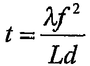
- While the foregoing off-axis illumination schemes and interferometric architectures are extremely effective in reducing the effects of coherent artifacts in normally configured interferometers, their use for this purpose in non-normally configured interferometric architectures containing retroreflective elements, for example, cat's eyes, is less efficacious. This is so because a point-source moved from the optical axis to a location off-axis in a non-normal cavity configuration results in one of the reflected waves traveling back to the original position (the wave, reflecting in the focus point of the transmission sphere), and the image of the light source is re-imaged onto its original position. The other wave reflects as from an ordinary mirror, and the image is opposite to the original position at the other side of the optical axis. Therefore tilt is introduced into the fringe system, and this tilt Is so strong, that the fringes cannot be resolved with the CCD-camera.
- To understand how tilt fringes are introduced with an non-normal configuration, it will be useful to revisit what takes place within a normal configuration interferometer using off-axis illumination. When the incident plane wave enters the Fizeau-lens (see
Fig. 6 for example) with an inclination angle, α , to the normal of the optical axis, the case when a light source with a distance y = f tan(α) off the optical axis of the collimating lens of the interferometer is used, the two plane waves, after reflecting at the spherical mirrors of the reference surface and the properly aligned test surface, both leave the Fizeau-lens with the same inclination angle of -α. Thus, no tilt fringes are formed on the detector. The "object point" to be imaged by the two spherical mirrors is located off-axis by an amount y 1 = f 1 tan(α1), where f 1 is the focal length of the Fizeau-lens. Both image points are located opposite to the object points on the other side of the optical axis of the lens. They coincide because the magnification, β, of the imaging of a spherical mirror is independent of its radius of curvature when the object point is in the near vicinity of the center point of the sphere. Very weak aberrations are introduced by the small displacement from the true center point of the spherical surfaces, and these aberrations depend on the radii of curvature of the two spheres. Because of the differences in radii, they do not completely cancel and will, in principle, be visible in the resulting interferogram. But when the azimuthal position of the point source at the focal plane of the collimator is changed, i.e., when the point source describes one full circle with constant radius around the optical axis, the aberrations contained in the integrated interferogram are averaged to a zero-mean value because none of the different aberration terms (like coma and astigmatism, to name only the most prominent) are rotationally symmetrical. - Having reviewed the operation of "normal use" of a Fizeau-lens in connection with the invention, the non-normal situation will now be discussed. This will be done by considering an arrangement which is used frequently in connection with a calibration procedure called the three position test. In this test, which is said to lead to an absolute knowledge of the spherical test surface, two of three measurements are done in the "normal" configuration as described above, whereas the third one uses the cat's eye configuration in connection with a normal reflection of the spherical wavefront at the spherical reference surface as illustrated in
Fig. 10 and elaborated on later. Briefly though, the result of this test configuration is a so-called rotational shear interferogram, where the two interfering wavefronts are rotated by 180° with respect to each other. That is the wanted effect for this third configuration, to supply the necessary information for the absolute evaluation of the test-surface errors in connection with the other two measurements. - Reference is now made to
Fig. 10 which shows non-normally configured cavity with a Fizeau lens (transmission sphere) 500 with an inclined incident plane wavefront 1a1b and resulting wavefronts 1a'1b' from reflection of thereference surface lens 500 is inclined at an angle α, the two waves reflected from the two surfaces are inclined by angles -α and +α, therefore producing tilt fringes with a fringe spacing of

- The solution to this "cat's eye" problem is to use two coherent plane wavefronts with inclination angles of opposite sign to illuminate the non-normal Fizeau-lens simultaneously. This configuration is shown in
Figure 11 . Here, two inclined coherent wavefronts 1a1b and 2a2b illuminating the Fizeau-lens leads to twowavefronts 1b"1a" and 2a'2b' which are not inclined to each other and another twowavefronts 2b"2a" and 1a'1b' with are also not inclined to each other and therefore lead to useful interference-fringe systems without tilt fringes. These two-wave interferences stem in both cases from the phase-difference between the reference surface and the cat's eye wavefront. In addition, both two-wave-systems produce very fine interference fringe systems as before, since they are inclined at an angle 2α to each other and coherent with each other. - It is shown by
Figure 11 that, in addition to the two useful fringe systems with no tilt-fringes, there is an additional fringe system with the same high-density tilt fringes as before. This second fringe system can be smeared out when the fringes are rotated by 360° during the integration time for one camera frame (i.e. during about 30ms). Note, that the useful interference pattern is not rotated when the plane containing the inclination angles of the in bouncing waves rotate azimuthally with the optical axis being the axis of rotation. - There are a number of ways by which two inclined coherent wavefronts can be produced. One preferred embodiment is shown In
Fig. 12 . InFig. 12 , the coherent plane wavefront from alaser 510 is expanded by abeam expander 512 and then impinges on a rotating phase-grating 516. When grating 516 is shown inFig. 13 , all even diffraction orders will be very weak, giving rise to about 40% of the energy within the first and minus first order. Grating 516 is located behind an afocal system consisting of an "ocular lens" 518 with focal length f1 and a "collimator lens" 520 with focal length f2, known as a "Kepler telescope". In the common focal plane of both lenses, it is possible to introduce a physical aperture (glass-plate with a chromium layer forming a ring-shaped aperture) to block spurious orders ofdiffraction grating 516. - It is possible to image the
diffraction grating 516 with this configuration. InFig. 12 , the image is located near thecollimator lens 520; but if the distance z1 is changed, the location of image of grating 516 is also changed and another location can be chosen, for instance the location at the reference surface of the Fizeau-lens, seeFig. 11 . This change in distance of z1 does not alter the location of the ring-shaped aperture behind theocular lens 518. Thediffraction grating 516, again, is shown inFig. 13 . - Another embodiment for producing two symmetrically located points is shown in
Fig. 14 which showsprismatic elements beamsplitter 526 to generate two oppositely located point sources that travel over identical optical path lengths. -
Fig. 15 shows yet another embodiment for generating two coherent plane wavefronts tilted symmetrical to the optical axis by means of using a rotational shearing interferometer. As mentioned earlier, a rotating grating must be adjusted very precisely to introduce no phase-changes between the two diffraction orders used during rotation. With a holographic element that produces a ring of a very high number of sources, together with the rotation of a ground glass to make these sources mutually incoherent, the holographic element is a flip-in device which is not critical to adjust and the ground glass need not be adjusted laterally at all; its axis of rotation being arbitrary. Another approach is to include a rotational shearing interferometer as a device that is able to produce, in addition, an identical copy of the wavefront, but rotated by 180° with respect to the original position. As shown inFig. 15 , alaser 530 undergoes beam expansion viaexpander 532. The expanded beam is received by aholographic device 530 to produce a ring, which is received by arotating ground glass 536 to make all points of the ring incoherent to each other. A rotational shearing interferometer 538 (RSI) produces two identical copies (same dynamic of phase changes) of the wavefront from therotating ground glass 536, but rotated with respect to each other by 180°. Afterwards, abeam expander 540 comprising an ocular and a collimator lens (neither shown) enlarges the two tilted wavefronts. Abeamsplitter 542 is provided in the beam expander for directing returning wavefronts to a CCD device (not shown). Two coherent plane tiltedwavefronts beam expander 540 and enter atransmission sphere 546 with a confocal reference surface. The cat's eye mirror is designated at 548. As a consequence of this structure the deleterious effects of tilted wavefronts with a cat's eye configuration also are ameliorated. - Let the two wavefronts generated by the
shearing interferometer 538 be designated as A0 and A180 (SeeFig. 16C ). If both wavefronts enter the Fizeau transmission sphere, which is used in the cat's eye position, the following wavefronts are produced: - B0 from the reference surface and B180 from the cat's eye surface out of A0
- B180 from the reference surface and B0 from the cat's eye surface out of A180
- Now it is possible that the two wavefronts B0 as well as the two wavefronts B180 interfere with each other in macroscopic resolvable, coherent interferograms because the microstructures of the wavefronts are correlated.
- But now both partners for the interference stem from different illumination wavefronts. That means the device that produced A0 and A180 may introduce different aberrations into these wavefronts. Therefore, it is necessary to re-investigate the procedure for absolutely measuring the wavefront of the test surface with the inclusion of A0 and A180.
- For the investigation of the equations, a very simplified, schematic version of the arrangement is used, where sources of errors are summarized in a very small number of terms. The three measurements performed are expressed with terms introduced in
Figs. 16A through 16C , showing schematically the three measurements. - Let the three wavefronts measured W1, W2 and W3. The errors which are included in the measurements are expressed by the following three equations, Eqs. 14, 15, and 16. For clarity, the distinction is made between a reference wavefront and a test wavefront here, which are finally subtracted from each other. Terms, which are common to both wavefronts, are first expressed twice, before they are cancelled with each other. Also, the following abbreviations are used:
- A0 Phase-map introduced by the ground glass + the errors of the RSI for the first arm
- A180 Phase-map of ground glass in rotated pos. + the errors of the RSI for the second arm
- L0 WEF caused by the lens in single transmission in initial position
- L180 WFE caused by the lens in single transmission in rotated position
- T0 WEF caused by the test surface in reflection in initial position
- T180 WEF caused by the test surface in reflection in rotated position
- R0 WEF caused by the reference surface in reflection in initial position
- R180 WEF caused by the reference surface in reflection in rotated
position 


- For the final evaluation, two of the measured wavefronts are rotated by software by 180°. This is again denoted by a bar above the wavefronts. We rotate W2 and W3.


- As with the original algorithm (Jensen and Schwider), the following equation is used for the extraction of the test surface errors T:

- The validity of the result can be proven by substituting the terms given in equations (14) to (18) into equation (19). That means, that the correct results are still gained for the absolute test procedures of spheres in the case with an additional rotational shear interferometer introduced in the test-set-up.
- The
rotational shearing interferometer 538 may be realized in a number of ways.Fig. 17 , for example, illustrates a rotational shear interferometer in which Dove-prisms are oppositely rotated by 45° to generate two symmetrically located points. Another solution for this task is shown inFigs. 18 and19 , where a new type of rotational shear interferometer is shown, which is made of only three pieces of glass. It is a symmetrical design, somewhat similar to a Sagnac interferometer, but it is not really cyclic. Therefore, the errors introduced in the two legs may differ and do not automatically cancel. The bundle enters a Koester's prism, is split into two halves and both are then reflected by aprism 604 made as a four-sided pyramid. The beams now leave their original plane; that is, where a rotation of both beams by 90° is introduced. The final relative rotation of the beams is the sum of those two rotations, i.e., 180°. After that reflection on the two mirrors of the pyramid, each of the beams enters the Koester'sprism 602 again, and they are finally recombined by a beamsplitter. They leave theprism 604 at another height and on the other side of the Koester'sprism 602. - In
Fig. 19 , the use of such a rotational shear interferometer in an interferometer mainframe is shown. Here, a focusinglens 610 converges an input beam to a holographic element 612 to produce a ring. The ring then encounters arotating diffuser 614 located at the focus of thecollimator lens 608, and then enters the Koester'sprism 602, after which it is treated as described above. It is obvious fromFig. 19 that a change in the direction of the incident bundle by 60° is encountered; but the change in height is not visible inFig. 19 . - In order not to increase the construction length of such a mainframe by the use of the rotational shear interferometer, it is advantageous to introduce the device in the diverging beam before the
collimator lens 608. This is possible because of the complete symmetry in path-length in both arms. The path-length in glass is considerable, which is made clear inFig. 20 . In the case, which is assumed for the drawings, the path-length in glass is about 44% of the focal length of thecollimator 608, which is believed to be a typical value. In any case, the thick plane parallel plate made of glass must be considered for the optical design of thecollimator lens 608. It should be noted, that the optical arrangement ofFig. 19 differs slightly from the arrangement inFig. 15 . - Another possible way to realize two wavefronts with pairs of coherent sources with the same phase on opposite sides with respect to the optical axis involves the use of a scatterplate. The basic procedure for making a scatterplate is to expose a photographic plate to a speckle pattern produced by illuminating a piece of ground glass with a laser beam. Since the scatterplate must have inversion symmetry, two superimposed exposures to the speckle pattern must be made, where the plate is rotated 180° between the exposures. To ensure that the scatterplate illuminates the surface under test as uniformly as possible during the making of the scatterplate, the solid angle subtended by the illuminated piece of ground glass, as viewed from the photographic plate, should be at least as large as the solid angle of the surface under test viewed from the scatterplate during the test. After development, the photographic plate should be bleached to yield a phase scatterplate. The exposure, development, and bleaching should be controlled so that the scatterplate scatters 10% to 20% of the incident light. For present purposes, the scatterplate should be illuminated by the ground glass for production with a numerical aperture larger than that used in the collimator lens, and the exposure, development and beaching should be done such that the highest amount of scattered light is reached, and the two exposures should be done in the original holder, which inherently contains a high precision bearing for rotation. Thus, the optical center coincides automatically with the mechanical center of the scatterplate.
- To use the scatterplate, an arrangement as shown in
Fig. 21 is made. The only alignment needs are to align the holder of thescatterplate 620 with respect to the optical axis, which is defined by the apex of thelens 624 and the symmetry center of theholographic device 622. - A solution to the problem using a holographic axicon together with a rotating, rotational symmetric scatterplate would also be very elegant because these two devices do the job of
- a normal holographic device producing a ring of light-sources with random phase,
- a normal rotating diffuser, and
- a rotational shearing interferometer.
- There are other ways to produce two points located symmetrical in opposite positions to the optical axis in the focal plane of the collimator lens. For instance, a Wollaston prism could be used together with quarter-wave plates. In addition, it is possible to use a disk with two oppositely spaced clear apertures, but this would not make efficient use of available light.
- It should be noted that it may be useful to produce more than two coherent points at a time. This can be done with special holographic elements. For instance, the pattern of points of
Fig. 22 in the common focal plane ofFig. 15 might be very useful. If such a configuration of 6 illumination points is used, the rotation speed of the element can be reduced by a factor of three, which might be important to avoid high-speed motors and bearings. The unwanted interference fringe systems are coarser in this case, but only by a factor of two compared to the two-point system of the grating 516 fromFig. 13 , which is still adequate. It can be argued that even a higher number of points on the circle might be feasible because the unwanted interference systems will rotate, and therefore, be washed out in the average. But coherent points too close inFig. 22 produce coarser fringe systems, and a noise component is introduced into a waveband of spatial frequencies where the useful information to be measured is also located. This should be avoided in high precision measurements. - In
figures 23a to 23d , it is shown that the axis of rotation for the grating ofFig. 13 , or the holographic device ofFig. 22 , should precisely coincide with the middle of a grating period, where the grating is located with respect to the axis so that it is an "even function" (cos-like, not sin-like), in order not to introduce a phase-term in its Fourier transformation.Figs. 23a and 23b show possible acceptable locations for the rotation axis of the grating;Fig. 23a shows the rotation axis coincident with the optical. axis whileFig. 23b shows another possibility.Fig. 23c shows an impossible location for the rotation axis because it introduces a phase shift of 2π between the coherent beams when the grating is rotated by 180°.Fig. 23d shows a case where there is a severe phase shift of 5x2π where the axis of rotation is off by 2.5 lines of the grating from the optical axis. The useful interference systems here are washed out when the integration time is chosen to be equal to the time of one revolution of the grating. - In view of the foregoing, it should be apparent that the use to at least two oppositely spaced off-axis points of illumination, while solving the tilted fringe problem introduced by a retroreflector in the interferometric cavity, also may be used beneficially with normal interferometer architectures to reduce the effects of coherent artifacts.
- It should be mentioned that the invention is not restricted to the case of Fizeau interferometers, but can be applied with all other kinds of interferometers including, but not limited to, unequal path types such as the Mirau and Twyman-Green. The principle underlying the invention can equally be applied to the testing of spheres. In addition, use may be made of one or more beam steering mirrors driven by galvanometers or the like in place of rotating wedges.
Claims (30)
- An interferometric apparatus (10; 100; 200; 300; 400; 500; 600) having an optical axis (OA) and comprising:means for locating an object (102; 504; 548) to be measured along the optical axis (OA);a detector (50; 122);an optical arrangement adapted to at least in part cooperate with the object (102; 504; 548) to form an interferometer cavity and facilitate the generation of interfering wavefronts in which phase information about the object (102; 504; 548) is encoded and imaged on to the detector (50; 122); andradiation directing means for directing radiation onto the object (102; 504; 548) to be measured,the apparatus (10; 100; 200; 300; 400; 500; 600) being characterized in that the radiation directing means is adapted to direct radiation at the object (102; 504; 548) from at least two different off-axis points of illumination that are distant from the optical axis (OA) such that radiation from each of the different off-axis points of illumination is incident to the same points on the object (102; 504; 548) along optical paths having identical optical path differences within the interferometer cavity to generate interfering wavefronts corresponding to each of the off-axis points of illumination, each wavefront containing substantially identical phase information about the object (102; 504; 548) and being added together incoherently at the same point on the detector (50; 122), each of the interfering wavefronts corresponding to each of the different off-axis points of illumination also including unwanted phase information that is averaged on the detector (50; 122).
- An apparatus according to claim 1 characterized in that the different off-axis points of illumination are equidistant from the optical axis (OA), oppositely spaced along an azimuth through the optical axis (OA), and the radiation therefrom is mutually coherent.
- An apparatus according to claim 2 characterized in that the radiation directing means comprises any one or more of the following mounted for rotation about the optical axis:(a) a diffraction grating (516).(b) a holographic element (620);(c) a beam splitter (526) and two prismatic elements (522, 524) coupled, respectively, to two different facets of the beam splitter (526); and(d) a disk having a pair of oppositely spaced clear apertures.
- An apparatus according to claim 2 characterized in that the radiation directing means comprises a rotational shearing interferometer (538).
- An apparatus according to claim 4 characterized in that the rotational shearing interferometer (538) comprises a pair of oppositely rotated Dove prisms (526, 528).
- An apparatus according to any one of the preceding claims characterized in that the radiation directing means directs radiation toward the object from two different locations equidistant from the optical axis.
- An apparatus according to claim 6 characterized in that the two equidistant locations lie in a plane substantially perpendicular to the optical axis.
- An apparatus according to claim 1 characterized in that the radiation directing means comprises a point source (S) mounted for movement around the optical axis.
- An apparatus according to claim 1 characterized in that the radiation directing means comprises at least one ring source (406, 408) having a nominally constant radius and nominally centered on the optical axis.
- An apparatus according to claim 9 characterized in that the ring source comprises a multimode fiber (406) of circular cross-section excited by a pump source (402) so that the emergent modal pattern from the output end of the multimode fiber (406) is in the form of an annular ring to form the ring source.
- An apparatus according to claim 9 characterized in that the ring source comprises an axicon.
- An apparatus according to claim 11 characterized in that the axicon comprises a diffractive element.
- An apparatus according to any one of the preceding claims characterized in that the radiation directing means comprises imaging means for selectively imaging a point source around the optical axis so that it appears to be originating from the different locations distant with respect to the optical axis.
- An apparatus according to claim 13 characterized in that the imaging means comprises any one or more of:(a) at least one rotating wedge (108);(b) a pair of serially arranged rotating wedges (204, 206);(c) a beam splitter (112) mounted for rotation in one azimuth and a wedge (108) mounted for rotation in another azimuth; and(d) serially arranged mirrors (205, 209), one mounted for rotation in azimuth and the other for rotation in elevation.
- An apparatus according to any one of the preceding claims characterized by means for facilitating phase shifting interferometric analysis of selected characteristics of the object.
- An apparatus according to any one of the preceding claims characterized in that the radiation directing means is adapted to collimate the radiation.
- An apparatus according to claim 1 characterized in that the imaging means comprises collimating and converging lenses (304, 306).
- An apparatus according to claims 1 or 17 characterized in that the detector receives an interferogrammetric image to generate an electronic output signal for subsequent analysis, the detector having a given sampling rate.
- An apparatus according to claim 18 characterized in that the interferogrammetric image is formed during a predetermined time period that is no more than the period of the given sampling rate of the detector.
- An apparatus according to claim 18 or 19 characterized in that the predetermined time period is substantially zero so that the object to be measured receives radiation from the at least two locations substantially simultaneously.
- An interferometric method comprising:locating an object (102; 504; 548) to be measured along an optical axis (OA);providing a detector (50; 122);arranging optical components adapted to at least in part cooperate with the object (102; 504; 548) to form an interferometer cavity and facilitate the generation of interfering wavefronts in which phase information about the object (102; 504; 548) is encoded and imaged on to the detector (50; 122); anddirecting radiation onto the object (102; 504; 548) to be measured,the method being characterized in that the radiation is directed toward the object (102; 504; 548) from at least two different off-axis points of illumination that are distant from the optical axis (OA) such that radiation from each of the different off-axis points of illumination is incident to the same points on the object (102; 504; 548) along optical paths having identical optical path differences within the interferometer cavity to generate interfering wavefronts corresponding to each of the off-axis points of illumination, each wavefront containing substantially identical phase information about the object (102; 504; 548) in the interferometer cavity and being added together incoherently at the same point on the detector (50; 122), each of the interfering wavefronts corresponding to each of the different off-axis points of illumination also including unwanted phase information that is averaged on the detector (50; 122).
- A method according to claim 21 characterized in that the different off-axis points of illumination are equidistant from the optical axis, oppositely spaced along an azimuth through the optical axis, and the radiation therefrom is mutually coherent.
- A method according to claim 22 characterized in that the radiation is directed by any one or more of the following mounted for rotation about the optical axis OA:(a) a diffraction grating (516);(b) a holographic element (620);(c) a beam splitter (526) and two prismatic elements (522, 524) coupled, respectively, to two different facets of the beam splitter (526); and(d) a disk having a pair of oppositely spaced clear apertures.
- A method according to claim 22 characterized in that the radiation is directed by a rotational shearing interferometer (538).
- A method according to claim 24 characterized in that the rotational shearing interferometer (538) comprises a pair of oppositely rotated Dove prisms (526, 528).
- A method according to any one of claims 21 to 25 characterized in that the radiation is directed by at least one ring source (406, 408) having a nominally constant radius and nominally centered on the optical axis.
- A method according to claim 21 characterized by introducing phase shifts in the interfering wavefronts and performing phase shifting interferometric analysis to determine selected characteristics of the object.
- A method according to claim 27 characterized in that the phase shifts are introduced into the interfering wavefronts by changing the radial position of the two off-axis points of illumination.
- A method according to claim 21 characterized in that the detector detects an interferogrammetric image and generates an electronic output signal for subsequent analysis, the detecting step occurring during a given sampling period.
- A method according to claim 29 characterized in that the interferogrammetric image is formed during a time that is no more than the given sampling period.
Applications Claiming Priority (5)
| Application Number | Priority Date | Filing Date | Title |
|---|---|---|---|
| DE10121516A DE10121516A1 (en) | 2001-05-03 | 2001-05-03 | Illuminating apparatus for an object under test in an interferometer with an optical axis (OA) has radiation director directing radiation at object from different locations distant from axis |
| DE10121516 | 2001-05-03 | ||
| US53741 | 2002-01-22 | ||
| US10/053,741 US6804011B2 (en) | 2001-05-03 | 2002-01-22 | Apparatus and method(s) for reducing the effects of coherent artifacts in an interferometer |
| PCT/EP2002/003169 WO2002090880A1 (en) | 2001-05-03 | 2002-03-21 | Reducing coherent artifacts in an interferometer |
Publications (2)
| Publication Number | Publication Date |
|---|---|
| EP1384044A1 EP1384044A1 (en) | 2004-01-28 |
| EP1384044B1 true EP1384044B1 (en) | 2018-06-27 |
Family
ID=26009216
Family Applications (1)
| Application Number | Title | Priority Date | Filing Date |
|---|---|---|---|
| EP02719995.9A Expired - Lifetime EP1384044B1 (en) | 2001-05-03 | 2002-03-21 | Reducing coherent artifacts in an interferometer |
Country Status (3)
| Country | Link |
|---|---|
| EP (1) | EP1384044B1 (en) |
| JP (1) | JP4286001B2 (en) |
| WO (1) | WO2002090880A1 (en) |
Cited By (1)
| Publication number | Priority date | Publication date | Assignee | Title |
|---|---|---|---|---|
| WO2023051939A1 (en) * | 2021-10-01 | 2023-04-06 | Carl Zeiss Smt Gmbh | Method for characterizing the surface shape of an optical element, and interferometric test arrangement |
Families Citing this family (5)
| Publication number | Priority date | Publication date | Assignee | Title |
|---|---|---|---|---|
| EP1869399A2 (en) | 2005-04-11 | 2007-12-26 | Zetetic Institute | Apparatus and method for in situ and ex situ measurement of spatial impulse response of an optical system using phase-shifting point-diffraction interferometry |
| US7428058B2 (en) | 2005-05-18 | 2008-09-23 | Zetetic Institute | Apparatus and method for in situ and ex situ measurements of optical system flare |
| DE102007045332B4 (en) * | 2007-09-17 | 2019-01-17 | Seereal Technologies S.A. | Holographic display for reconstructing a scene |
| DE102015222789A1 (en) | 2014-12-11 | 2016-06-16 | Carl Zeiss Smt Gmbh | Interferometric measurement of an optical surface |
| PL246642B1 (en) * | 2022-04-06 | 2025-02-17 | Politechnika Warszawska | Method of setting precise angular rotations using a laser interferometer, especially for calibrating angular encoders |
Citations (5)
| Publication number | Priority date | Publication date | Assignee | Title |
|---|---|---|---|---|
| US3958884A (en) * | 1974-04-24 | 1976-05-25 | Vickers Limited | Interferometric apparatus |
| US5995224A (en) * | 1998-01-28 | 1999-11-30 | Zygo Corporation | Full-field geometrically-desensitized interferometer employing diffractive and conventional optics |
| US5999262A (en) * | 1996-04-19 | 1999-12-07 | Carl Zeiss Jena Gmbh | Process and apparatus for detecting structural changes of specimens |
| US6072581A (en) * | 1998-10-30 | 2000-06-06 | Zygo Corporation | Geometrically-desensitized interferometer incorporating an optical assembly with high stray-beam management capability |
| WO2001020295A2 (en) * | 1999-09-15 | 2001-03-22 | Proteoptics Ltd | Plasmon resonance phase imaging |
Family Cites Families (4)
| Publication number | Priority date | Publication date | Assignee | Title |
|---|---|---|---|---|
| JPS62168008A (en) * | 1986-01-20 | 1987-07-24 | Ricoh Co Ltd | Measuring instrument for aspherical shape |
| DE4124223C2 (en) * | 1991-07-22 | 2001-07-26 | Zeiss Carl | Procedure for evaluating interferograms and interferometers |
| DE4233336C2 (en) * | 1992-10-05 | 2001-08-23 | Zeiss Carl | Method and device for detecting focus deposits |
| US6031612A (en) * | 1996-02-12 | 2000-02-29 | Massachusetts Institute Of Technology | Apparatus and methods for contour measurement using movable sources |
-
2002
- 2002-03-21 JP JP2002587897A patent/JP4286001B2/en not_active Expired - Lifetime
- 2002-03-21 EP EP02719995.9A patent/EP1384044B1/en not_active Expired - Lifetime
- 2002-03-21 WO PCT/EP2002/003169 patent/WO2002090880A1/en not_active Ceased
Patent Citations (5)
| Publication number | Priority date | Publication date | Assignee | Title |
|---|---|---|---|---|
| US3958884A (en) * | 1974-04-24 | 1976-05-25 | Vickers Limited | Interferometric apparatus |
| US5999262A (en) * | 1996-04-19 | 1999-12-07 | Carl Zeiss Jena Gmbh | Process and apparatus for detecting structural changes of specimens |
| US5995224A (en) * | 1998-01-28 | 1999-11-30 | Zygo Corporation | Full-field geometrically-desensitized interferometer employing diffractive and conventional optics |
| US6072581A (en) * | 1998-10-30 | 2000-06-06 | Zygo Corporation | Geometrically-desensitized interferometer incorporating an optical assembly with high stray-beam management capability |
| WO2001020295A2 (en) * | 1999-09-15 | 2001-03-22 | Proteoptics Ltd | Plasmon resonance phase imaging |
Cited By (1)
| Publication number | Priority date | Publication date | Assignee | Title |
|---|---|---|---|---|
| WO2023051939A1 (en) * | 2021-10-01 | 2023-04-06 | Carl Zeiss Smt Gmbh | Method for characterizing the surface shape of an optical element, and interferometric test arrangement |
Also Published As
| Publication number | Publication date |
|---|---|
| JP4286001B2 (en) | 2009-06-24 |
| JP2004525381A (en) | 2004-08-19 |
| EP1384044A1 (en) | 2004-01-28 |
| WO2002090880A1 (en) | 2002-11-14 |
Similar Documents
| Publication | Publication Date | Title |
|---|---|---|
| US6804011B2 (en) | Apparatus and method(s) for reducing the effects of coherent artifacts in an interferometer | |
| EP1390689B1 (en) | Reducing coherent artifacts in an interferometer | |
| US8593642B2 (en) | Method of measuring a shape of an optical surface based on computationally combined surface region measurements and interferometric measuring device | |
| US7218403B2 (en) | Scanning interferometer for aspheric surfaces and wavefronts | |
| EP1397640B1 (en) | Scanning interferometer for aspheric surfaces and wavefronts | |
| EP1405030B1 (en) | Scanning interferometer for aspheric surfaces and wavefronts | |
| US10527403B2 (en) | Measuring device for interferometric determination of a shape of an optical surface | |
| US6226092B1 (en) | Full-field geometrically desensitized interferometer using refractive optics | |
| US11231269B2 (en) | Arrangement and method for robust single-shot interferometry | |
| US6876456B2 (en) | Absolute calibration of optical flats | |
| US5737081A (en) | Extended-source low coherence interferometer for flatness testing | |
| JP4286001B2 (en) | Reduction of coherent artifacts in interferometers | |
| JP3439803B2 (en) | Method and apparatus for detecting displacement or change in position of an object from the focal point of an objective lens | |
| Tiziani | Optical techniques for shape measurements | |
| Yan et al. | Cophasing calibration for a segmented telescope based on two-dimensional dispersed interferograms | |
| Malacara | Basic interferometers | |
| JP3150761B2 (en) | Simple phase shift interferometer | |
| JPH08219737A (en) | Interferometer | |
| Page | Interferometry | |
| Simon et al. | The Mach-Zehnder interferometer: examination of a volume by non-classical localization plane shifting | |
| Malacara-Hernández | Basic Interferometers | |
| Voznesensky et al. | Principles of highest-precision optical parts estimation on the basis of a point-diffraction interferometer | |
| Malacara-Hernández | Optics for Engineers | |
| Dukhopel | Interference and interferometry | |
| Schwider | Characterization of Interconnection Components |
Legal Events
| Date | Code | Title | Description |
|---|---|---|---|
| PUAI | Public reference made under article 153(3) epc to a published international application that has entered the european phase |
Free format text: ORIGINAL CODE: 0009012 |
|
| 17P | Request for examination filed |
Effective date: 20031029 |
|
| AK | Designated contracting states |
Kind code of ref document: A1 Designated state(s): AT BE CH CY DE DK ES FI FR GB GR IE IT LI LU MC NL PT SE TR |
|
| 17Q | First examination report despatched |
Effective date: 20091118 |
|
| GRAP | Despatch of communication of intention to grant a patent |
Free format text: ORIGINAL CODE: EPIDOSNIGR1 |
|
| RIC1 | Information provided on ipc code assigned before grant |
Ipc: G01J 9/02 20060101ALI20171208BHEP Ipc: G01B 9/02 20060101AFI20171208BHEP |
|
| INTG | Intention to grant announced |
Effective date: 20180117 |
|
| RBV | Designated contracting states (corrected) |
Designated state(s): DE |
|
| GRAS | Grant fee paid |
Free format text: ORIGINAL CODE: EPIDOSNIGR3 |
|
| GRAA | (expected) grant |
Free format text: ORIGINAL CODE: 0009210 |
|
| AK | Designated contracting states |
Kind code of ref document: B1 Designated state(s): DE |
|
| REG | Reference to a national code |
Ref country code: DE Ref legal event code: R096 Ref document number: 60249492 Country of ref document: DE |
|
| RIC2 | Information provided on ipc code assigned after grant |
Ipc: G01J 9/02 20060101ALI20171208BHEP Ipc: G01B 9/02 20060101AFI20171208BHEP |
|
| REG | Reference to a national code |
Ref country code: DE Ref legal event code: R097 Ref document number: 60249492 Country of ref document: DE |
|
| PLBE | No opposition filed within time limit |
Free format text: ORIGINAL CODE: 0009261 |
|
| STAA | Information on the status of an ep patent application or granted ep patent |
Free format text: STATUS: NO OPPOSITION FILED WITHIN TIME LIMIT |
|
| 26N | No opposition filed |
Effective date: 20190328 |
|
| PGFP | Annual fee paid to national office [announced via postgrant information from national office to epo] |
Ref country code: DE Payment date: 20210329 Year of fee payment: 20 |
|
| REG | Reference to a national code |
Ref country code: DE Ref legal event code: R071 Ref document number: 60249492 Country of ref document: DE |