EP1383355A1 - Mosi 2? arc-shaped heater, and method and device for manufacturing the heater - Google Patents
Mosi 2? arc-shaped heater, and method and device for manufacturing the heater Download PDFInfo
- Publication number
- EP1383355A1 EP1383355A1 EP02711289A EP02711289A EP1383355A1 EP 1383355 A1 EP1383355 A1 EP 1383355A1 EP 02711289 A EP02711289 A EP 02711289A EP 02711289 A EP02711289 A EP 02711289A EP 1383355 A1 EP1383355 A1 EP 1383355A1
- Authority
- EP
- European Patent Office
- Prior art keywords
- arc
- shaped heater
- mosi
- shaped
- members
- Prior art date
- Legal status (The legal status is an assumption and is not a legal conclusion. Google has not performed a legal analysis and makes no representation as to the accuracy of the status listed.)
- Granted
Links
Images


Classifications
-
- H—ELECTRICITY
- H05—ELECTRIC TECHNIQUES NOT OTHERWISE PROVIDED FOR
- H05B—ELECTRIC HEATING; ELECTRIC LIGHT SOURCES NOT OTHERWISE PROVIDED FOR; CIRCUIT ARRANGEMENTS FOR ELECTRIC LIGHT SOURCES, IN GENERAL
- H05B3/00—Ohmic-resistance heating
- H05B3/10—Heating elements characterised by the composition or nature of the materials or by the arrangement of the conductor
- H05B3/12—Heating elements characterised by the composition or nature of the materials or by the arrangement of the conductor characterised by the composition or nature of the conductive material
- H05B3/14—Heating elements characterised by the composition or nature of the materials or by the arrangement of the conductor characterised by the composition or nature of the conductive material the material being non-metallic
-
- H—ELECTRICITY
- H05—ELECTRIC TECHNIQUES NOT OTHERWISE PROVIDED FOR
- H05B—ELECTRIC HEATING; ELECTRIC LIGHT SOURCES NOT OTHERWISE PROVIDED FOR; CIRCUIT ARRANGEMENTS FOR ELECTRIC LIGHT SOURCES, IN GENERAL
- H05B3/00—Ohmic-resistance heating
- H05B3/62—Heating elements specially adapted for furnaces
-
- B—PERFORMING OPERATIONS; TRANSPORTING
- B23—MACHINE TOOLS; METAL-WORKING NOT OTHERWISE PROVIDED FOR
- B23K—SOLDERING OR UNSOLDERING; WELDING; CLADDING OR PLATING BY SOLDERING OR WELDING; CUTTING BY APPLYING HEAT LOCALLY, e.g. FLAME CUTTING; WORKING BY LASER BEAM
- B23K1/00—Soldering, e.g. brazing, or unsoldering
- B23K1/005—Soldering by means of radiant energy
- B23K1/0053—Soldering by means of radiant energy soldering by means of infrared [IR]
-
- B—PERFORMING OPERATIONS; TRANSPORTING
- B23—MACHINE TOOLS; METAL-WORKING NOT OTHERWISE PROVIDED FOR
- B23K—SOLDERING OR UNSOLDERING; WELDING; CLADDING OR PLATING BY SOLDERING OR WELDING; CUTTING BY APPLYING HEAT LOCALLY, e.g. FLAME CUTTING; WORKING BY LASER BEAM
- B23K1/00—Soldering, e.g. brazing, or unsoldering
- B23K1/008—Soldering within a furnace
-
- H—ELECTRICITY
- H05—ELECTRIC TECHNIQUES NOT OTHERWISE PROVIDED FOR
- H05B—ELECTRIC HEATING; ELECTRIC LIGHT SOURCES NOT OTHERWISE PROVIDED FOR; CIRCUIT ARRANGEMENTS FOR ELECTRIC LIGHT SOURCES, IN GENERAL
- H05B3/00—Ohmic-resistance heating
- H05B3/10—Heating elements characterised by the composition or nature of the materials or by the arrangement of the conductor
- H05B3/12—Heating elements characterised by the composition or nature of the materials or by the arrangement of the conductor characterised by the composition or nature of the conductive material
- H05B3/14—Heating elements characterised by the composition or nature of the materials or by the arrangement of the conductor characterised by the composition or nature of the conductive material the material being non-metallic
- H05B3/141—Conductive ceramics, e.g. metal oxides, metal carbides, barium titanate, ferrites, zirconia, vitrous compounds
- H05B3/143—Conductive ceramics, e.g. metal oxides, metal carbides, barium titanate, ferrites, zirconia, vitrous compounds applied to semiconductors, e.g. wafers heating
-
- H—ELECTRICITY
- H05—ELECTRIC TECHNIQUES NOT OTHERWISE PROVIDED FOR
- H05B—ELECTRIC HEATING; ELECTRIC LIGHT SOURCES NOT OTHERWISE PROVIDED FOR; CIRCUIT ARRANGEMENTS FOR ELECTRIC LIGHT SOURCES, IN GENERAL
- H05B3/00—Ohmic-resistance heating
- H05B3/62—Heating elements specially adapted for furnaces
- H05B3/64—Heating elements specially adapted for furnaces using ribbon, rod, or wire heater
-
- H—ELECTRICITY
- H05—ELECTRIC TECHNIQUES NOT OTHERWISE PROVIDED FOR
- H05B—ELECTRIC HEATING; ELECTRIC LIGHT SOURCES NOT OTHERWISE PROVIDED FOR; CIRCUIT ARRANGEMENTS FOR ELECTRIC LIGHT SOURCES, IN GENERAL
- H05B2203/00—Aspects relating to Ohmic resistive heating covered by group H05B3/00
- H05B2203/018—Heaters using heating elements comprising mosi2
-
- Y—GENERAL TAGGING OF NEW TECHNOLOGICAL DEVELOPMENTS; GENERAL TAGGING OF CROSS-SECTIONAL TECHNOLOGIES SPANNING OVER SEVERAL SECTIONS OF THE IPC; TECHNICAL SUBJECTS COVERED BY FORMER USPC CROSS-REFERENCE ART COLLECTIONS [XRACs] AND DIGESTS
- Y10—TECHNICAL SUBJECTS COVERED BY FORMER USPC
- Y10T—TECHNICAL SUBJECTS COVERED BY FORMER US CLASSIFICATION
- Y10T29/00—Metal working
- Y10T29/49—Method of mechanical manufacture
- Y10T29/49002—Electrical device making
- Y10T29/49082—Resistor making
- Y10T29/49083—Heater type
Definitions
- the present invention pertains to a MoSi 2 arc-shaped heater for use in the likes of a heating furnace and which is superior in joining strength and capable of being manufactured stably, and to a method and a device for manufacturing such a heater.
- the MoSi 2 heater used in the present specification includes heaters having MoSi 2 as its principal component with increased electrical resistance in which insulative oxides or the like are included in pure MoSi 2 , or MoSi 2 .
- MoSi 2 Molybdenum Disilicide
- a heater employed in various fields such as the glass industry or for ceramics calcination has a shape in which a heating part (moreover, a "heating part” usually means the portion of the heater having a small diameter (excluding terminal parts) that mainly generates heat during energization) forms a single U shape (2-shank shape) and is mounted by being suspended from the ceiling or sidewall of the furnace, whereby the maximum temperature during use of such furnace reaches 1700 to 1850°C.
- a heating part usually means the portion of the heater having a small diameter (excluding terminal parts) that mainly generates heat during energization) forms a single U shape (2-shank shape) and is mounted by being suspended from the ceiling or sidewall of the furnace, whereby the maximum temperature during use of such furnace reaches 1700 to 1850°C.
- heaters having MoSi 2 as its principal component are now being used in semiconductor manufacturing devices such as single crystal growth furnaces and diffusion furnaces in which metal heating elements were conventionally employed.
- a heater having MoSi 2 as its principal component possesses superior heat resistance characteristics and is capable of enduring a surface load of approximately ten times that of metal heating elements, and further possesses a significant characteristic in that it is capable of rapid heating and temperature rising.
- a heat treating furnace employed in semiconductor manufacturing devices is demanded of extreme high-precision temperature characteristics such as stringently controlling the temperature distribution within the furnace.
- a heater having MoSi 2 as its principal component generally employed is a U-shaped heater in which terminal parts are welded to both ends of a U-shaped heating part as shown in Fig. 5.
- the U-shaped heater 21 shown in Fig. 5 is structured of a heating part 22, a welding part 23, a grip (terminal) part 24, and an electrode part 25.
- An object of the present invention is to provide a MoSi 2 arc-shaped heater wherein a large number of parallel U-shaped heater members having heating parts are connected to each other and welded so that the heater can have a generally arc-shaped curved surface for installing such heater onto the inner wall of a heating furnace, which is superior in joining strength and capable of being manufactured stably, and a method and a device for manufactured such a heater.
- a MoSi 2 arc-shaped heater can be accurately and stably manufactured by devising the disposition of MoSi 2 U-shaped heater members during the welding thereof, and the supporting method of such welded U-shaped heater members.
- the present invention provides:
- a MoSi 2 arc-shaped heater is mounted on the inner wall of a furnace by penetrating its terminal through the hole provided to a fire-resistant furnace wall. As one reason the temperature within the furnace becomes uneven, it could be said that heat is released via this terminal or from such through-hole and the temperature of the terminal (vicinity) is thereby reduced.
- the number of terminals can be reduced as much as possible, but it is desirable to make U-shaped heaters have a structure of being connected half way or all around along the inner wall of a cylindrical furnace. For example, if it is of a half way connected structure, the number of terminals will be four, and if it is of an all around connected structure, the number of terminals will be 2, thereby decreasing the number of terminals effectively.
- MoSi 2 arc-shaped heater forming a planar continuous waveform in which U-shaped heater members having parallel parts are connected alternately to each other at the end parts, and heat it to a higher temperature and bend it into an arc shape.
- the present invention provides a method and a device for manufacturing a MoSi 2 arc-shaped heater capable of being precisely and stably welded, by electrically heating U-shaped heater members having parallel parts.
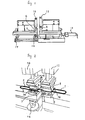
- Fig. 1 is an explanatory diagram showing the appearance of the device upon welding MoSi 2 U-shaped heater members
- Fig. 2 is a perspective view of the device for forming a continuous waveform by connecting alternately to each other the MoSi 2 U-shaped heater members 1 having parallel parts 2, 3 and alternately displacing and connecting the end parts 4, 5.
- two U-shaped heater members 1 are retained between the vertical electrodes 6, 7 and between electrodes 8, 9, respectively, one end of the U-shaped heater members 1 are made to contact each other, and welded through energization.
- each of the U-shaped heater members 1, and the foregoing vertical electrodes 6, 7 and 8, 9 are respectively required to comprise a structure capable of being adjusted in vertical and cross directions as well as in the direction allowing the separation from and contact with each other.
- the electrodes are formed of materials such as copper.
- the use of fluid pressure devices 10, 11 such as air cylinders or hydraulic cylinders is appropriate. Otherwise, a mechanical means such as a crank mechanism may also be employed.
- a guide is provided to the surface of the electrodes for aligning the MoSi 2 U-shaped heater members 1.
- This guide may be a convex guide 13 or a groove guide 14 aligned to the parallel parts of the U-shaped heater members 1.
- the retention position of the vertical electrodes 6, 7 and electrodes 8, 9 retaining each of the U-shaped heater members 1 therebetween is positioned slightly forward of the connecting direction of the U-shaped heater member 1 than the working point of the fluid pressure device.
- L-shaped terminal parts may also be welded, and the connecting operation and connecting (welding) status can be easily observed.
- a fluid pressure device such as an air cylinder or hydraulic cylinder as illustrated in Fig. 1.
- only one pair of the electrodes retaining the U-shaped heater member 1 therebetween may be made to move horizontally, and the other pair may be fixed.
- each U-shaped heater member 1 Upon welding, it is necessary that the connecting end faces of each U-shaped heater member 1 be aligned properly. If this is insufficient, an accident of rupturing from the connecting part may occur easily.
- reference numeral 16 represents the vertical adjuster of the electrodes
- reference numeral 17 represents the cross direction adjuster of the electrodes.
- each U-shaped heater member 1 it is necessary to give the parallel faces of each U-shaped heater member 1 an angle relative to each other and to weld such faces. Thereby, although each individual U-shaped heater member 1 will have parallel parts within the same plane, between the other U-shaped heater members 1, such parallel parts are not on the same plane. In other words, by repeating this kind of connection, the U-shaped heater members 1 are in succession joined to each other and connected in an arc, whereby obtained is a MoSi2 arc-shaped heater.
- adjusting the said angle could change the curvature of the curved surface of the arc-shaped heater or the size of the arc.
- each U-shaped heater member 1 When giving the parallel faces of each U-shaped heater member 1 an angle relative to each other and welding such faces, as depicted in Fig. 3 and Fig. 4, by providing an arc-shaped guide 15 for guiding and supporting the connected U-shaped heater members 1 in the connecting direction of such U-shaped heater members 1, the angle could be adjusted easier. Moreover, when changing the curvature of the curved surface of the arc-shaped heater or the size of the arc, by exchanging this arc-shaped guide 15, such change can be achieved easily. Further, Fig. 4 shows a condition where the terminal part 18 is retained between and connected to the vertical electrodes. In addition, for ease of understanding, only a part of the continuous arc-shaped heater 1 is shown in Fig. 4.
- FIG. 3 illustrates two arc-shaped guides 15, as evident from the diagram, each of the connected U-shaped heater members 1 is alternately aligned horizontally of the welding portions of the electrodes, and the connected U-shaped heater members 1 are formed successively so as to rise along the arc-shaped guide 15.
- an insulating body such as an insulation tape
- an adhesive or cohesive material such as a double-sided tape or magic tape
- the arc-shaped heaters of a half circle or having a specified length prepared in advance do not necessarily have to be welded, and, for instance, there is an advantage in that they may be arc-shaped heaters continuously formed in a U shape through bending.
- the arc-shaped heater continuously formed in a U shape through bending does not have a welding part, it has a characteristic in having a stronger strength in comparison to a welded heater, and, by leveraging such characteristic, a method may also be selected where numerous arc-shaped heaters are continuously formed in a U shape through bending, and thereafter connecting a portion thereof through welding.
- the method and device for manufacturing such a MoSi 2 arc-shaped heater are also included therein.
- the arc-shaped guide 15 for guiding and supporting the U-shaped heater member 1 or the curvature of the U-shaped heater member 1 is made to have a curvature approximately coinciding with, or slightly smaller than, the inner wall curvature surface of the heating furnace.
- an arc-shaped heater is installed to a position roughly 2 to 5mm apart from the inner wall of the heating furnace; that is, in a state where it has a slightly smaller diameter in the central direction of the furnace.
- the arc-shaped guide for guiding and supporting such arc-shaped heater is slightly smaller than the curved surface of the inner wall of the furnace, and made to have a radius that is 2 to 5mm smaller than such inner wall.
- the arc-shaped guide 15 for guiding and supporting the U-shaped heater member 1 of the present invention or the U-shaped heater 1 has a curvature approximately coinciding with, or slightly smaller than, the inner wall curved surface of the heating furnace, and includes such curvature.
- the MoSi 2 arc-shaped heater of the present invention may be formed in a shape of being disposed at a part of the inner wall of the heating furnace, or half way or all around the inner wall of the heating furnace as a continuous MoSi 2 arc-shaped heater.
- a continuous MoSi 2 arc-shaped heater when the continuous MoSi 2 arc-shaped heater is disposed half way, two sets are prepared and disposed around the entire inner periphery of the heating furnace.
- arc-shaped heaters corresponding thereto are suitably prepared and arranged to enable the installation around the entire inner periphery of the heating furnace.
- Mounting of the MoSi 2 arc-shaped heater to the terminal may be performed by exchanging the electrodes having the retention grooves matching the shape of the terminal, and welding such portion with the same device.
- the present invention yields a significant characteristic in that obtained is an arc-shaped face having a specified curvature in a connecting direction by connecting a plurality of parallel U-shaped heater members having a heating part, giving the parallel parts of each U-shaped heater member an angle relative to each other and then welding such parts, and, as a result of the heater being provided with an overall arc-shaped curved surface capable of being installed in the inner wall of a heating furnace or the like, further obtained is a MoSi 2 arc-shaped heater superior in joining strength and capable of being manufactured stably.
Landscapes
- Engineering & Computer Science (AREA)
- Mechanical Engineering (AREA)
- Chemical & Material Sciences (AREA)
- Ceramic Engineering (AREA)
- Resistance Heating (AREA)
Abstract
Description
Claims (20)
- A MoSi2 arc-shaped heater formed in a continuous waveform, characterized in that U-shaped heater members having parallel parts are connected alternately to each other at the end parts, and the parallel faces of the U-shaped heater members have an angle relative to each other and an arc-shaped face with a specified curvature in a connecting direction.
- A MoSi2 arc-shaped heater according to claim 1, characterized in comprising a curvature approximately coinciding with the inner wall curved surface of a heating furnace.
- A MoSi2 arc-shaped heater according to claim 1 or claim 2, characterized in comprising a shape in which the continuous MoSi2 arc-shaped heaters are disposed half way or all around the inner wall of the heating furnace.
- A manufacturing method of a MoSi2 arc-shaped heater for forming a continuous waveform in which U-shaped heater members having parallel parts are connected alternately to each other at the end parts, characterized in that the end faces are aligned while each U-shaped heater member is retained in parallel during the connection, each U-shaped heater member is welded while an angle relative to each other is given to the parallel faces thereof, and an arc-shaped face with a specified curvature in a connecting direction is obtained thereby.
- A manufacturing method of a MoSi2 arc-shaped heater, characterized in that, with the two series-connected MoSi2 arc-shaped heater members having a specified arc length in which U shapes are connected alternately to each other to form a continuous waveform, the end face of a U-shaped heater member located at the end of an arc-shaped heater member is aligned while said arc-shaped heater member is retained in parallel, each U-shaped heater member is welded while an angle relative to each other is given to the parallel faces thereof, whereby said two series-connected MoSi2 arc-shaped heater members are joined at the same time, and an arc-shaped face with a specified curvature in a connecting direction is obtained thereby.
- A manufacturing method of a MoSi2 arc-shaped heater according to claim 5, characterized in that the two series-connected MoSi2 arc-shaped heater members are heater members formed in a U-shape through welding or bending.
- A manufacturing method of a MoSi2 arc-shaped heater according to each of claims 4 to 6, characterized in that the parallel faces of the U-shaped heater members are given an angle relative to each other by employing an arc-shaped guide for guiding and supporting said connected U-shaped heater members.
- A manufacturing method of a MoSi2 arc-shaped heater according to each of claims 4 to 7, characterized in comprising a curvature approximately coinciding with the inner wall curved surface of a heating furnace.
- A manufacturing method of a MoSi2 arc-shaped heater according to each of claims 4 to 8, characterized in comprising a shape in which the continuous MoSi2 arc-shaped heaters are disposed half way or all around the inner wall of the heating furnace.
- A manufacturing device of a MoSi2 arc-shaped heater for forming a continuous waveform in which U-shaped heater members having parallel parts are connected alternately to each other at the end parts, or for joining at the same time two series-connected MoSi2 arc-shaped heater members having a specified arc length in which U shapes are connected alternately to each other to form a continuous waveform, characterized in that the end faces are aligned while each U-shaped heater member is retained in parallel during the connection, and each U-shaped heater member is welded while an angle relative to each other is given to the parallel faces thereof, or characterized in that the end faces are aligned while each U-shaped heater member is retained in parallel during the connection and providing an electrode to be welded in which each U-shaped heater member is welded while an angle relative to each other is given to the parallel faces thereof; and an arc-shaped face with a specified curvature in a connecting direction is obtained thereby.
- A manufacturing device of a MoSi2 arc-shaped heater according to claim 10, characterized in that the two series-connected MoSi2 arc-shaped heater members are heater members formed in a U-shape through welding or bending.
- A manufacturing device of a MoSi2 arc-shaped heater according to claim 10 or claim 11, characterized in that the U-shaped heater member is retained between the electrodes, one end of each of the U-shaped heater members are made to contact each other, and the joint surface is mutually pressurized and welded through electrical heating.
- A manufacturing device of a MoSi2 arc-shaped heater according to claim 12, characterized in that a guide for mutually retaining in parallel each U-shaped heater member is provided to the electrodes retaining the U-shaped heater member therebetween.
- A manufacturing device of a MoSi2 arc-shaped heater according to each of claims 10 to 13, characterized in that an arc-shaped guide for guiding and supporting said connected U-shaped heater members or arc-shaped heater members is provided in the connecting direction of the U-shaped heater members or arc-shaped heater members.
- A manufacturing device of a MoSi2 arc-shaped heater according to claim 14, characterized in that the arc-shaped guide for guiding and supporting said connected U-shaped heater members or arc-shaped heater members comprises a curvature approximately coinciding with the inner wall curved surface of a heating furnace.
- A manufacturing device of a MoSi2 arc-shaped heater according to each of claims 10 to 15, characterized in that the electrodes retaining the U-shaped heater member therebetween comprises a structure capable of respectively operating vertically and in a direction of mutually separating from or contacting each other.
- A manufacturing device of a MoSi2 arc-shaped heater according to claim 16, characterized in that at least one of the electrodes retaining the U-shaped heater member therebetween is activated with a fluid pressure device.
- A manufacturing device of a MoSi2 arc-shaped heater according to claim 16 or claim 17, characterized in that the retention position of the electrodes retaining the U-shaped heater member therebetween is of a position slightly in front of the connecting direction of the U-shaped heater member than the working point of the fluid pressure device.
- A manufacturing device of a MoSi2 arc-shaped heater according to each of claims 14 to 18, characterized in that an insulating body for preventing short circuits is provided to the curved surface part of the arc-shaped guide.
- A manufacturing device of a MoSi2 arc-shaped heater according to each of claims 14 to 19, characterized in that an adhesive or cohesive material is provided to the curved surface part of the arc-shaped guide.
Applications Claiming Priority (3)
| Application Number | Priority Date | Filing Date | Title |
|---|---|---|---|
| JP2001131559 | 2001-04-27 | ||
| JP2001131559A JP3876131B2 (en) | 2001-04-27 | 2001-04-27 | MoSi2 arc heater and method and apparatus for manufacturing the same |
| PCT/JP2002/000870 WO2002091800A1 (en) | 2001-04-27 | 2002-02-04 | Mosi2 arc-shaped heater, and method and device for manufacturing the heater |
Publications (3)
| Publication Number | Publication Date |
|---|---|
| EP1383355A1 true EP1383355A1 (en) | 2004-01-21 |
| EP1383355A4 EP1383355A4 (en) | 2007-03-28 |
| EP1383355B1 EP1383355B1 (en) | 2008-10-29 |
Family
ID=18979725
Family Applications (1)
| Application Number | Title | Priority Date | Filing Date |
|---|---|---|---|
| EP02711289A Expired - Lifetime EP1383355B1 (en) | 2001-04-27 | 2002-02-04 | MoSi2 ARC-SHAPED HEATER, AND METHOD AND DEVICE FOR MANUFACTURING THE HEATER |
Country Status (7)
| Country | Link |
|---|---|
| US (1) | US6844532B2 (en) |
| EP (1) | EP1383355B1 (en) |
| JP (1) | JP3876131B2 (en) |
| KR (1) | KR100544959B1 (en) |
| CN (1) | CN1321546C (en) |
| TW (1) | TWI243151B (en) |
| WO (1) | WO2002091800A1 (en) |
Families Citing this family (6)
| Publication number | Priority date | Publication date | Assignee | Title |
|---|---|---|---|---|
| KR100930031B1 (en) * | 2007-10-23 | 2009-12-04 | 이상범 | Electric stove and its control method |
| US9908197B2 (en) | 2013-03-15 | 2018-03-06 | Automated Industrial Machinery, Inc. | Wire butt welder with adjustable alignment |
| CN103231449B (en) * | 2013-04-07 | 2015-10-14 | 上海交通大学 | A kind of energizing heating bending device fast |
| US11123790B2 (en) | 2017-10-16 | 2021-09-21 | General Electric Company | Apparatus for casting a mold |
| US11123791B2 (en) | 2017-10-16 | 2021-09-21 | General Electric Company | Method for casting a mold |
| JP6892064B2 (en) * | 2019-03-29 | 2021-06-18 | Jx金属株式会社 | Multi-shank type heater |
Family Cites Families (17)
| Publication number | Priority date | Publication date | Assignee | Title |
|---|---|---|---|---|
| DE2045357A1 (en) * | 1969-09-16 | 1971-03-25 | Kanthal Ab | Electrical resistance element |
| US3912905A (en) * | 1974-02-25 | 1975-10-14 | Kanthal Corp | Electric resistance heating device |
| US4016403A (en) * | 1975-05-01 | 1977-04-05 | National Element Inc. | Electrical heating element |
| US4147888A (en) * | 1977-07-20 | 1979-04-03 | Seiki Sato | Electric heating element for electric resistance furnaces |
| US4266119A (en) * | 1979-08-15 | 1981-05-05 | The Kanthal Corporation | Hairpin-type electric resistance heating element |
| US4267435A (en) * | 1979-08-23 | 1981-05-12 | The Kanthal Corporation | Electric resistance heating element |
| JPH0714604B2 (en) * | 1990-08-31 | 1995-02-22 | 株式会社リケン | Automatic molding device and method for molybdenum disilicide heating element |
| JPH04155822A (en) | 1990-10-18 | 1992-05-28 | Tokyo Electron Sagami Ltd | Heat treatment device |
| US5324920A (en) | 1990-10-18 | 1994-06-28 | Tokyo Electron Sagami Limited | Heat treatment apparatus |
| US5449886A (en) * | 1993-03-09 | 1995-09-12 | University Of Cincinnati | Electric heating element assembly |
| US5507639A (en) | 1993-06-30 | 1996-04-16 | Tokyo Electron Kabushiki Kaisha | Heat treatment apparatus and method thereof |
| JP3020773B2 (en) | 1993-07-06 | 2000-03-15 | 東京エレクトロン株式会社 | Heat treatment equipment |
| US5473141A (en) * | 1993-10-26 | 1995-12-05 | The Kanthal Corporation | Radiant tube heating assembly |
| JPH08143365A (en) * | 1994-11-15 | 1996-06-04 | Riken Corp | Molybdenum disilic ide heater |
| JP3504784B2 (en) * | 1995-09-07 | 2004-03-08 | 東京エレクトロン株式会社 | Heat treatment method |
| JPH10291875A (en) * | 1997-04-22 | 1998-11-04 | Riken Corp | Automatic bending and forming device of ceramic bar material and forming method therefor |
| JP3657800B2 (en) * | 1998-02-20 | 2005-06-08 | 株式会社リケン | Molybdenum disilicide-based composite ceramic heating element and manufacturing method thereof |
-
2001
- 2001-04-27 JP JP2001131559A patent/JP3876131B2/en not_active Expired - Lifetime
-
2002
- 2002-02-04 EP EP02711289A patent/EP1383355B1/en not_active Expired - Lifetime
- 2002-02-04 US US10/399,896 patent/US6844532B2/en not_active Expired - Lifetime
- 2002-02-04 KR KR1020037013834A patent/KR100544959B1/en not_active Expired - Lifetime
- 2002-02-04 WO PCT/JP2002/000870 patent/WO2002091800A1/en not_active Ceased
- 2002-02-04 CN CNB028025857A patent/CN1321546C/en not_active Expired - Lifetime
- 2002-03-15 TW TW091104966A patent/TWI243151B/en not_active IP Right Cessation
Also Published As
| Publication number | Publication date |
|---|---|
| WO2002091800A1 (en) | 2002-11-14 |
| US20040094536A1 (en) | 2004-05-20 |
| JP2002329568A (en) | 2002-11-15 |
| CN1465208A (en) | 2003-12-31 |
| KR100544959B1 (en) | 2006-01-24 |
| EP1383355B1 (en) | 2008-10-29 |
| EP1383355A4 (en) | 2007-03-28 |
| CN1321546C (en) | 2007-06-13 |
| US6844532B2 (en) | 2005-01-18 |
| TWI243151B (en) | 2005-11-11 |
| KR20040015122A (en) | 2004-02-18 |
| JP3876131B2 (en) | 2007-01-31 |
Similar Documents
| Publication | Publication Date | Title |
|---|---|---|
| US6259193B1 (en) | Emissive filament and support structure | |
| US11043401B2 (en) | Ceramic member | |
| EP1351281B1 (en) | Ceramic heaters | |
| US10840117B2 (en) | Holding apparatus | |
| EP1383355B1 (en) | MoSi2 ARC-SHAPED HEATER, AND METHOD AND DEVICE FOR MANUFACTURING THE HEATER | |
| KR102893329B1 (en) | Car for kiln having heating structure and kiln comprising the same | |
| US20100266319A1 (en) | Heat generation unit and heating apparatus | |
| US20120223639A1 (en) | Method for manufacturing a conductive connection of a metallic electrode wire and a metallic lead-in wire | |
| KR20240125839A (en) | Multi zone heater | |
| JP2018182280A (en) | Ceramic member | |
| EP1376653A2 (en) | Metal halide lamp | |
| EP1703546A2 (en) | Processing device | |
| EP1780787B1 (en) | Joining structure between ceramic substrate and power supply connector | |
| KR101904490B1 (en) | Joint structure of ceramic heater | |
| US7223145B2 (en) | Fluorescent lamp having meandering discharge path and manufacturing method of the same | |
| JP2005515593A (en) | Discharge lamp | |
| US4045645A (en) | Welding process for slotted tungsten rod | |
| KR102139886B1 (en) | Electric heat wall with good thermal efficiency and electric heat furnace thereof | |
| KR102935240B1 (en) | Heating structure for firing | |
| CN113170538A (en) | Multi-handle type heater | |
| JP4053277B2 (en) | Electric furnace | |
| JP2003151725A (en) | Heating element | |
| CN208609212U (en) | A kind of infrared radiator | |
| JP2580216B2 (en) | Heater heater | |
| CN108933071A (en) | The fixed structure and fixing means of silicon wafer and the cathode assembly of X-ray tube |
Legal Events
| Date | Code | Title | Description |
|---|---|---|---|
| PUAI | Public reference made under article 153(3) epc to a published international application that has entered the european phase |
Free format text: ORIGINAL CODE: 0009012 |
|
| 17P | Request for examination filed |
Effective date: 20030411 |
|
| AK | Designated contracting states |
Kind code of ref document: A1 Designated state(s): AT BE CH CY DE DK ES FI FR GB GR IE IT LI LU MC NL PT SE TR |
|
| RAP1 | Party data changed (applicant data changed or rights of an application transferred) |
Owner name: NIKKO MATERIALS CO., LTD. |
|
| REG | Reference to a national code |
Ref country code: DE Ref legal event code: 8566 |
|
| RAP1 | Party data changed (applicant data changed or rights of an application transferred) |
Owner name: NIPPON MINING & METALS CO., LTD. |
|
| A4 | Supplementary search report drawn up and despatched |
Effective date: 20070228 |
|
| 17Q | First examination report despatched |
Effective date: 20070807 |
|
| GRAP | Despatch of communication of intention to grant a patent |
Free format text: ORIGINAL CODE: EPIDOSNIGR1 |
|
| RBV | Designated contracting states (corrected) |
Designated state(s): SE |
|
| RTI1 | Title (correction) |
Free format text: MOSI2 ARC-SHAPED HEATER, AND METHOD AND DEVICE FOR MANUFACTURING THE HEATER |
|
| GRAS | Grant fee paid |
Free format text: ORIGINAL CODE: EPIDOSNIGR3 |
|
| GRAA | (expected) grant |
Free format text: ORIGINAL CODE: 0009210 |
|
| AK | Designated contracting states |
Kind code of ref document: B1 Designated state(s): SE |
|
| REG | Reference to a national code |
Ref country code: SE Ref legal event code: TRGR |
|
| PLBE | No opposition filed within time limit |
Free format text: ORIGINAL CODE: 0009261 |
|
| STAA | Information on the status of an ep patent application or granted ep patent |
Free format text: STATUS: NO OPPOSITION FILED WITHIN TIME LIMIT |
|
| 26N | No opposition filed |
Effective date: 20090730 |
|
| PGFP | Annual fee paid to national office [announced via postgrant information from national office to epo] |
Ref country code: SE Payment date: 20210210 Year of fee payment: 20 |
|
| REG | Reference to a national code |
Ref country code: SE Ref legal event code: EUG |