EP1383309A2 - Adaptive motion detection and control - Google Patents
Adaptive motion detection and control Download PDFInfo
- Publication number
- EP1383309A2 EP1383309A2 EP03016044A EP03016044A EP1383309A2 EP 1383309 A2 EP1383309 A2 EP 1383309A2 EP 03016044 A EP03016044 A EP 03016044A EP 03016044 A EP03016044 A EP 03016044A EP 1383309 A2 EP1383309 A2 EP 1383309A2
- Authority
- EP
- European Patent Office
- Prior art keywords
- motion
- signals
- values
- pixels
- response
- Prior art date
- Legal status (The legal status is an assumption and is not a legal conclusion. Google has not performed a legal analysis and makes no representation as to the accuracy of the status listed.)
- Withdrawn
Links
Images


Classifications
-
- H—ELECTRICITY
- H04—ELECTRIC COMMUNICATION TECHNIQUE
- H04N—PICTORIAL COMMUNICATION, e.g. TELEVISION
- H04N5/00—Details of television systems
- H04N5/14—Picture signal circuitry for video frequency region
- H04N5/144—Movement detection
-
- G—PHYSICS
- G06—COMPUTING OR CALCULATING; COUNTING
- G06T—IMAGE DATA PROCESSING OR GENERATION, IN GENERAL
- G06T7/00—Image analysis
- G06T7/20—Analysis of motion
- G06T7/254—Analysis of motion involving subtraction of images
-
- H—ELECTRICITY
- H04—ELECTRIC COMMUNICATION TECHNIQUE
- H04N—PICTORIAL COMMUNICATION, e.g. TELEVISION
- H04N5/00—Details of television systems
- H04N5/14—Picture signal circuitry for video frequency region
- H04N5/21—Circuitry for suppressing or minimising disturbance, e.g. moiré or halo
Definitions
- This invention relates to detection of motion of images represented by video pixels and other digital data.
- One application of this invention is useful in connection with digitally removing noise from video sequences that have been digitized from the analog domain in order to increase the efficiency of a digital video compression system.
- Other applications of the invention are useful in connection with deinterlacing (line doubling) systems, and with comb filtering systems.
- Some known temporal filters derive motion information from both luminance and chrominance separately, not taking advantage of the correlation between the two signals.
- One apparatus embodiment of the invention is useful detecting motion represented by video pixels having digital pixel values.
- the apparatus comprises a memory arranged to store filtered pixel first values corresponding to first pixels processed by the apparatus during a first time period, and a motion detector responsive to differences between the first values and pixel second values corresponding to second pixels processed by the apparatus during a second time period later than the first time period to generate motion signals representing detected motion of images represented by the first pixels relative to motion of images represented by the second pixels.
- One method embodiment of the invention is useful for detecting motion represented by video pixels having digital pixel values.
- the method comprises storing filtered pixel first values corresponding to first pixels processed during a first time period and generating motion signals in response to differences between the first values and pixel second values corresponding to second pixels processed during a second time period later than the first time period, the motion signals representing detected motion of images represented by the first pixels relative to motion of images represented by the second pixels.
- motion detection can be accomplished with a degree of ease and accuracy previously unavailable.
- the motion detection module shown in the Figures converts frame-based temporal differences into a facsimile of motion between like-fields of video across video frames.
- the motion detected from the frame differences is also used to derive temporal characteristics of the video sequence in order to direct the behavior of other functions in the system.
- Chrominance motion information is derived from luminance motion information and is qualified by a series of dynamic parameters that take advantage of correlation between chrominance and luminance data.
- the motion detection module detects edge transitions in the motion signal in order to temporarily change the time constant of the recursive filter in order to further prevent temporal blurring, also known as ghosting (a common artifact byproduct of improperly implemented recursive filters). Furthermore, the embodiments make use of a median operator acting directly on the motion signal in order to detect impulses in the motion signal that may be caused by spurious noise in the input video signal.
- the input video sequence is analyzed specifically to detect impulsive noise in order to control the impulsive noise reduction filters. Furthermore, the input video sequence is also analyzed to detect moving edges in order to control the time constant of the recursive temporal filter structure.
- a dynamic process is one which is controlled by firmware according to information gathered over time.
- the firmware may control the process at various places, such as a video field boundary or a horizontal video line time.
- An example is the change in the general form of the motion look-up table shown in Figure 2 according to the amount of total motion detected over a period of time. This period can span several fields.
- the hardware continues to make motion-adaptive decisions regarding the recursive time constant for each pixel, but the overall shape of the motion transform function is controlled (loaded) dynamically (as needed) by the firmware.
- Figure 1 describes a preprocessor system 10 that processes input digital video pixels having digital pixel values received on an input 12. This process involves changing picture size, converting to MPEG color space, and noise reduction. The entire process is under the control of a central processing unit 15 that stores data in a memory 19.
- the CPU 15 is coupled to each of the blocks shown in Figure 1 through one or more busses 13. To avoid cluttering Figure 1, the connection of the busses to the various blocks has been omitted from the drawing.
- This specification describes ways of reducing random noise generated by low quality video signal sources, typically converted from the analog domain.
- One way of reducing noise is to perform spatial filtering, such as the spatial filtering performed by a 2D scaler/filter 14. This type of noise reduction can be effective but leads to loss of picture detail since it relies on attenuating high frequencies in which random noise is prevalent.
- a better way of reducing random noise is to use temporal information in the input sequence and filtering the noise in both spatial and temporal domains using linear and non-linear filter structures.
- FIG. 1 The top-level architecture of a complete motion detection module suitable as input stage to an MPEG encoder is depicted in Figure 1.
- the input to preprocessor system 10 is digital video which has been converted from the analog domain by an analog video decoder (not shown in Figure 1).
- the line buffer blocks 16-18 represent storage elements that may contain adjacent horizontal video lines necessary to perform vertical filtering. There is always a compromise in using internal buffers regarding silicon area and system bus access. It is convenient to store adjacent video lines in local buffers without having to utilize external memory bandwidth in accessing pixels across horizontal lines.
- line buffers are used to indicate storage necessary to perform operations along the vertical picture direction.
- a 2D Scaler/Filter module 20 performs both downscaling and spatial filtering, as well as cropping the input video to specific resolutions and bandwidth requirements.
- the MPEG Encoder will set the size and spatial filtering required for the appropriate video sequence, instantaneous compression factor, and bit stream produced.
- a previous frame block or buffer 22 holds picture information derived from a processing stage one frame-time in the past.
- the data written to block 22 is taken out of a motion adaptive recursive noise reduction filter 100. If desired, more than one previous frame block may be stored.
- a processed frame buffer 24 contains the completely processed frame and may be input to an MPEG Encoder module (not shown).
- buffer 22 stores a frame of pixels processed by preprocessor 10 at a time period earlier than the time period during which preprocessor 10 processes the current frame of pixels transmitted along a path 21.
- Line buffers 16-18 and frame buffers 22 and 24 form part of memory 19.
- Digital video signals are processed in the way they are captured by the analog digitizer, i.e., in the form of interlaced frames of video. Each frame consists of two fields of 1/60 th of a second duration. Horizontal and vertical synchronization signals derived from the input video are used to coordinate most of the processing operations described in the present architecture.
- the embodiments shown in the drawings also are effective for progressive sequences (non-interlaced).
- Implicit in the Figures is the insertion of matching processing delay elements.
- One example is the initial motion detection signal mDetect described in following sections. This signal is used to control the processing at various stages, but must be properly delayed to match the corresponding pixel being processed as the video signal travels through the processing elements.
- current frame indicates the luminance and chrominance signals as they are obtained directly from the digital video input port 12.
- Preprocessor 10 includes a temporal filter 26 comprising frame-recursive IIR type filter 100.
- Filter 100 is adaptively controlled by the amount of motion detected between images represented by pixels of consecutive frames by a motion detector 300.
- An image characterization module 400 is also included as shown in Figure 1.
- the main purpose of temporal filter 26 is to provide noise reduction for random non-correlated white gaussian type noise.
- the random noise in this case is the kind that can be generated from tape recordings, low quality broadcast transmissions, and system electronic noise that corrupts picture quality.
- This noise also can include what is widely known as snow in images sequences.
- the signal flow starts with the YCbCr 4:2:0 input data from the color space converter 20.
- the input data on path 21 is referred to as the current frame in later sections of this specification.
- the recursive filter 100 takes both the current and previous frame data and applies filter 100 with a coefficient (time constant).
- the image characterization module 400 keeps a record of the amount of motion of images in the current frame represented by pixels of the current frame, as well as a record of the data currently being processed.
- the main purpose of module 400 is to help the firmware decide on the optimal system parameters on a field-by-field basis. However, in other applications, the firmware may exercise control on a horizontal (i.e., line-by-line) basis.
- the recursive filter 100 depicted in Figure 1 works on the principle that random, uncorrelated noise can the filtered in the temporal domain for those regions of the picture where a neighborhood of pixels has remained essentially static for at least one frame-time. Since only one previous frame is stored, the motion detection of detector 300 is limited to a short period of time, but the effects of filter 100 can last much longer due to the recursive nature of filter 100.
- Motion detection by motion detector 300 is based on temporal frame differences, which are calculated by an arithmetic operator 30 that subtracts pixels residing in the same spatial locations, but one frame-time apart. Motion detector 300 takes the temporal frame differences and converts them into motion signals S that represent an estimate of detected motion. More specifically, motion detector 300 generates motion signals S representing detected motion of images represented by pixels of the previous frame relative to the motion of images represented by pixels of the current frame.
- Motion detector 300 does not estimate motion, it only detects it. For the purposes of the recursive filter 100, it is only necessary to know regions where there is essentially no motion, medium amount of motion and large amount of motion. The precise value of the motion at every pixel is not as important as the neighborhood amount of motion detected.
- the motion detection is based on the luminance signal. For the great majority of cases, large area luminance motion will be correlated with the chrominance signal.
- a motion look-up table 362 modifies initial motion signals generated by module 300. Typically, absolute values of the initial motion signals greater than 32 are considered very high motion within the small two-dimensional region processed and therefore the look-up table 362 usually consists of at most 32 entries.
- Firmware plays a role in the effective use of motion detector 300. With the help of information gathered by the image characterization module 400, the firmware can change the values of the motion look-up table 362 to better suit the temporal and signal quality nature of the input video pixels. Furthermore, firmware can change the register values that control the gain of S for both the luminance and chrominance components.
- the motion detection signal S is based on the temporal difference between frames.
- Figure 2 depicts a block diagram of the motion detector.
- the bit widths indicate the relevant signal information used at each stage.
- the 3-tap vertical filter 332 ( Figure 2) operates on 8-bit quantities, since the nature of the frame delta signal is such that its frequency distribution is concentrated largely around low values for most image sequences and because the motion detector detects only small, medium and large motion changes, the relevant information is limited to 5-bits and the programmable LUT is accessed by only 32 values in the illustrated embodiment.
- motion detector 300 includes a two dimensional (2D) smoothing filter 320 and a programmable transfer function module 360.
- the 2D smoothing filter 320 generates initial motion signals mDetect on a path 334.
- filter 320 includes an absolute value operator 322, a 3-tap horizontal median filter 324, a 5-tap horizontal finite impulse response (FIR) filter 326, a rounding and clipping operator 328, a line buffer 330 and a 3-tap vertical FIR filter 332 interconnected as shown.
- FIR finite impulse response
- Absolute value operator 322 calculates the absolute value of the difference between the amplitudes of pairs of corresponding pixels from the current frame on path 21 and the previous frame 22.
- the 3-tap median filter 324 is used to eliminate spurious pixel-wide motion between frames.
- the median filter 324 is a simple ranking operator that always selects the value that is numerically in the center of three consecutive motion samples.
- the absolute value of the temporal delta signal is low-pass filtered horizontally by filter 326 to further reduce high frequency components due to noise and to generate horizontal filtered signals.
- Filter 326 uses fixed coefficients that can be realized without multipliers:
- transfer function module 360 includes an edge detector 364, which provides an indication of a horizontal sudden change in the horizontal filtered signals in order to reduce artifacts produced by horizontal motion of high contrast edges in the images represented by the pixels in the current frame.
- the resulting effect is the improvement of artifacts caused by the application of a high time constant motion look-up table to video that has only localized motion components when high contrast object or image boundaries move across the current frame.
- Register medgeThr is used by detector 364 to determine what constitutes a motion edge of an image. For practical purposes, and based on simulation results, the value of medgeDetectGain is either 1.0, 1/2 or 0.0.
- the effect of medgeDetectGain is to quickly select the strength of the edge with a one-bit value and is limited to the edge boundaries of images, therefore being very short in duration.
- the edge signals generated by the output of the edge detector 364 are based on the absolute value of a simple horizontal high pass filter:
- Using vertical filter 332 for the frame delta signal further helps the conversion to a neighborhood motion detection signal.
- the output of filter 332 is saturated to 5-bits when used as msense, the input to the motion look-up table 362.
- the 8-bit initial motion detect signal, mDetect is used by other modules as a true motion detection signal.
- the vertical motion filter 332 is implemented as a simple filter with coefficients:
- the programmable look-up table 362 also is referred to as motion LUT or MLUT in other parts of this specification.
- the general form of table 362 is a monotonically decreasing function.
- the function can be either sinusoidal or exponential.
- Image sequences with large amounts of global motion should use MLUT functions that decay rapidly from the origin.
- Firmware has the option of changing the complete table at field boundaries or the option of only changing the attenuation factors depending on the nature of the input sequence (derived from information provided by image characterization module 400 and the encoding engine itself).
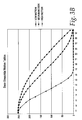
- Figure 3A shows a family of functions that have been successfully used for various types of input sequences. Notice that a curve with a base shape can be reduced in amplitude by means of the various adaptive gains (attenuators) in the system. The output of MLUT 362 must be in the range [0..255].
- the motion look-up tables depicted in Figure 3B also include sinusoidal versions, as well as the actual data used to generate them. The wider the curve, the more 'aggressive' it is in eliminating random noise. It is important for the curves to 'taper off' gradually as the input values increase to the maximum 32; otherwise motion artifacts can be generated in areas of similar -but not equal- amounts of motion.
- curve C1 is the most aggressive and curve C5 is the least aggressive.
- Curves C1-C5 represent various types of motion of images represented by pixels of the previous frame relative to motion of images represented by pixels of the current frame. More specifically, curves C1-C3 represent types of increasing medium motion, curve C4 represents large motion, and curve C5 represents very large motion.
- LUT 362 generates first modified motion signals based on the curves representing the transfer functions.
- the edge signals from edge detector 364 are multiplied by first modified motion signals generated by LUT 362 in an arithmetic operator 366 to generate motion signals S.
- image sequence characterization is used to indicate the process of gathering information and making decisions based on video sequence information.
- the hardware involved for this task is essentially a set of accumulators and counters that keep track of various spatial and temporal data.
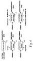
- Figure 4 shows the signal widths needed for image resolution according to ITU-R656. Horizontal and vertical synchronization signals are used to reset and start accumulating/counting operations, but the values of the previously computed field or line remain stable for the duration of the current field or line until the next synchronization event.
- TotalLumaFrmSum is calculated by a counter 402 that keeps track of the sum of all luma pixels in the current frame. This value is an early indication of the average DC value when scaled down by the total image size.
- TotalFrmMotion is calculated by a counter 404 that adds the motion detection signal mDetect for the entire current frame.
- TotalHLineMotion is a horizontal line motion signal calculated by a counter 406 that adds the mDetect signals for the horizontal line above the current horizontal line that includes a pixel being processed.
- Figure 4 indicates that counter 406 is reset at every vsync or every hsync of a frame.
- Firmware is responsible for reading the values at the appropriate interrupt before the counters are reset automatically by the hardware.
- TotalAreaNOmotion and TotalAreaHIGHmotion are calculated by counters 408 and 410, respectively.
- TotalAreaNOmotion is a low motion signal corresponding to motion of one or more images and TotalAreaHIGHmotion is a high motion signal corresponding to motion of one or more images.
- Counters 408 and 410 always count up by one as they are indicators of how many pixels fall within the threshold values indicated by the registers. At the end of each field, these registers contain an indication of how many pixels are at the extreme motion detection ranges indicated by the various thresholds. This information is used to globally change motion parameters, including the values of MLUT 362.
- preprocessor system 10 The overall operation of preprocessor system 10 will be described in the context of the interaction between hardware and firmware to provide motion detection.
- preprocessor system 10 depends on the interaction between hardware and firmware.
- the hardware is set up by the firmware via control registers and under the assumption of an input video sequence of pixels on path 12 has mild noise reduction requirements.
- the image characterization module 400 collects temporal and spatial features of the input sequence for the firmware to analyze.
- the firmware can determine after several frames have passed, more effective parameters for the noise reduction hardware.
- the firmware may determine that the input video has very little global motion. This is indicated by low values for TotalFrmMotion (typically less than 10% of total frame motion), and at the same time a high value for TotalAreaNoMotion (better than 80% of total frame locations).
- the firmware can temporarily set the global MotionGain and uvMotGain registers to reduce, eliminate or partially disable the effect of the recursive filter 100 (Figure 1) while the transition lasts.
- a rapid but progressive decrease in the value of TotalLumaFrmSum may indicate a fade-to-black video transition, especially if TotalAreaNoMotion remains fairly constant within the thresholds set for low/high motion.
- Each write to this register writes 4-bytes of motion coefficients to the MLUT 362.
- the address is cleared to zero at each field synch.
- each read gets 4 coefficients at a time starting at location zero.
- the values in these registers remain valid for the duration of the current field and are changed only at vertical or horizontal sync, as the case may be. This way, the firmware can always read the value of the previous field at ay time.
- the status count registers should not overflow.
- This register is double-buffered and guaranteed to always be ready by the firmware with stable values.
- Field Name Description 6:18 HmotionLineCount Indicates the horizontal line to which TotalHLineMotion belongs 7:0 TotalHLineMotion Adds all the motion detected between line above in the current frame and the line above in the previous frame
Landscapes
- Engineering & Computer Science (AREA)
- Multimedia (AREA)
- Computer Vision & Pattern Recognition (AREA)
- Physics & Mathematics (AREA)
- General Physics & Mathematics (AREA)
- Theoretical Computer Science (AREA)
- Signal Processing (AREA)
- Picture Signal Circuits (AREA)
- Image Analysis (AREA)
Abstract
Description
| it Field | Name | Description |
| :7 | MLPscale | Motion Horizontal Low Pass filter scale down factor. Implemented as a Shift Right operator of 3 bits. The filter coefficients are fixed. This gain helps extend the range of |
| MedgeEn able | Enable horizontal motion edge detection Enable horizontal motion edge detection | |
| :3 | medgeThr | Motion edge detection threshold sensitivity. Range [0..28] Actual value used is: {medgeThr[2:0], 2'b00} |
| Width select |
0: most significant 5-bits (saturated) are stored 1: all the bits are stored in line buffer | |
| Bypass MVF |
Bypass vertical motion low pass filter | |
| MHF Bypass |
Bypass horizontal motion median filter MHF |
| it Field | Name | Description | |
| 1:20 | | Coefficient | 3 |
| 3:16 3:16 | | Coefficient | 2 |
| 5:8 5:8 | MLUT1 | Coefficient 1 | |
| :0 | | Coefficient | 0 |
| it Field | Name | Description |
| 6:0 | TotalLumaFrmSum | Adds all pixels in luma for the current frame |
| it Field | Name | Description |
| 6:0 | TotalFrmMotion | Adds all the motion detected between the current and previous frames |
| it Field | Name | Description |
| 6:18 | HmotionLineCount | Indicates the horizontal line to which TotalHLineMotion belongs |
| 7:0 | TotalHLineMotion | Adds all the motion detected between line above in the current frame and the line above in the previous frame |
| it Field | Name | Description |
| 6:19 | NO Motion Threshold | All pixels with motion values detected below this threshold are considered static. |
| 8:0 | TotalAreaNoMotion | Counts all the pixel locations where there was no motion as indicated by the threshold value |
| it Field | Name | Description |
| 6:19 | HIGH Motion Threshold |
All pixels with motion values detected above this threshold are considered largely moving. |
| 8:0 | TotalAreaHigh Motion |
Counts all the pixel locations where there was a lot of motion as indicated by the threshold value |
Claims (32)
- Apparatus for detecting motion represented by video pixels having digital pixel values comprising:a memory arranged to store filtered pixel first values corresponding to first pixels processed by the apparatus during a first time period; anda motion detector responsive to differences between the first values and pixel second values corresponding to second pixels processed by the apparatus during a second time period later than the first time period to generate motion signals representing detected motion of images represented by the first pixels relative to motion of images represented by the second pixels.
- The apparatus of claim 1 wherein the second pixels correspond to lines comprising a horizontal first line and a horizontal second line, wherein a pixel being processed lies in the first line, wherein the images define moving edges and wherein the motion detector comprises:a third filter responsive to pixels in the first and second lines and responsive to the differences between the first values and the second values to generate initial motion signals representing an estimate of the detected motion of images; anda transfer function module arranged to generate the motion signals in response to the initial motion signals and characteristics of the images.
- The apparatus of claim 2, wherein the apparatus further comprises an image sequence characterization module arranged to sum the initial motion signals for the second line to generate horizontal line motion signals, and wherein the transfer function module generates the motion signals in response to the horizontal line motion signals.
- The apparatus of claim 2 wherein the transfer function module comprises a programmable module that modifies the initial motion signals in response to coefficients and wherein the apparatus further comprises an image sequence characterization module arranged to generate low motion signals having values derived from the second pixels corresponding to motion of one or more of the images less than a predetermined first threshold and to generate high motion signals having values derived from the second pixels corresponding to motion of one or more of the images greater than a predetermined second threshold, and wherein the coefficients are varied in response to at least one of the low motion signals and the high motion signals.
- The apparatus of claim 2 wherein the second pixels correspond to an area defining a horizontal direction and a vertical direction, wherein the images represent moving edges and wherein the characteristics of the images comprise:the proportion of the area representing one or more of the images with motion greater than a predetermined first threshold or less than a predetermined second threshold; andthe relation of the pixel being processed to one or more of the moving edges.
- The apparatus of claim 2 wherein the second pixels correspond to an area defining a horizontal direction and a vertical direction and wherein the transfer function module is arranged to generate the motion signals in response to the initial motion signals, in response to the second pixels corresponding to motion of one or more of the images beyond a threshold, and in response to the relationship of the pixel being processed to one or more of the moving edges.
- The apparatus of claim 2 wherein the third filter comprises:a horizontal filter module responsive to the differences between the first values and the second values and responsive to pixel values in the horizontal first line to generate horizontal filtered signals; anda vertical filter module responsive to the horizontal filtered signals and pixel values in the first and second lines to generate the initial motion signals.
- The apparatus of claim 7 wherein the horizontal filter module comprises:an absolute value operator arranged to generate absolute values corresponding to the differences between the first values and the second values;a median filter arranged to generate median filtered values in response to the absolute values; anda finite impulse response filter responsive to the median filtered values to generate the horizontal filtered signals.
- The apparatus of claim 8 wherein the second pixels correspond to an area defining a horizontal direction and a vertical direction and wherein the transfer function module comprises:a look up table defining a programmable transfer function altered in response to one or more of the extent to which the second pixels correspond to motion of one or more of the images less than a predetermined first threshold and the extent to which the second pixels correspond to motion of one or more of the images greater than a predetermined second threshold, the look up table being arranged to generate first modified motion signals in response to the initial motion signals;an edge detector responsive to the horizontal filtered signals to generate edge signals indicating one or more of the edges; andan arithmetic operator arranged to combine the edge signals with the first modified motion signals to generate the motion signals.
- The apparatus of claim 9 wherein the edge detector comprises a high pass filter.
- The apparatus of claim 7 wherein the second pixels correspond to an area defining a horizontal direction and a vertical direction and wherein the transfer function module comprises:a look up table defining a programmable transfer function altered in response to one or more of the extent to which the second pixels correspond to motion of one or more of the images less than a predetermined first threshold and the extent to which the second pixels correspond to motion of one or more of the images greater than a predetermined second threshold, the look up table being arranged to generate first modified motion signals in response to the initial motion signals;an edge detector responsive to the horizontal filtered signals to generate edge signals indicating one or more of the edges; andan arithmetic operator arranged to combine the edge signals with the first modified motion signals to generate the motion signals.
- The apparatus of claim 11 wherein the arithmetic operator comprises a multiply operator.
- The apparatus of claim 1 wherein the apparatus processes the pixels on a pixel-by-pixel basis.
- The apparatus of claim 1 wherein the first values comprise a first frame of data and the second values comprise a second frame of data.
- The apparatus of claim 14 wherein the differences between the first values and second values are derived from pixels in like positions of the first frame and second frame.
- The apparatus of claim 1 wherein the pixel values comprise pixel luminance values.
- A method of detecting motion represented by video pixels having digital pixel values comprising:storing filtered pixel first values corresponding to first pixels processed during a first time period; andgenerating motion signals in response to differences between the first values and pixel second values corresponding to second pixels processed during a second time period later than the first time period, the motion signals representing detected motion of images represented by the first pixels relative to motion of images represented by the second pixels.
- The method of claim 17 wherein the second pixels correspond to lines comprising a horizontal first line and a horizontal second line, wherein a pixel being processed lies in the first line, wherein the images define moving edges and wherein the generating motion signals comprises:generating initial motion signals representing an estimate of the detected motion of images in response to pixels in the first and second lines and responsive to the differences between the first values and the second values; andgenerating the motion signals in response to the initial motion signals and characteristics of the images.
- The method of claim 18, wherein generating the motion signals comprises summing the initial motion signals for the second line to generate horizontal line motion signals and generating the motion signals in response to the horizontal line motion signals.
- The method of claim 18 wherein generating the motion signals comprises modifying the initial motion signals in response to coefficients and wherein the method further comprises:generating low motion signals having values derived from the second pixels corresponding to motion of one or more of the images less than a predetermined first threshold;generating high motion signals having values derived from the second pixels corresponding to motion of one or more of the images greater than a predetermined second threshold; andvarying the coefficients in response to at least one of the low motion signals and the high motion signals.
- The method of claim 18 wherein the second pixels correspond to an area defining a horizontal direction and a vertical direction, wherein the images represent moving edges and wherein the characteristics of the images comprise:the proportion of the area representing one or more of the images with motion greater than a predetermined first threshold or less than a predetermined second threshold;the relation of the pixel being processed to one or more of the moving edges.
- The method of claim 18 wherein the second pixels correspond to an area defining a horizontal direction and a vertical direction and wherein the generating the motion signals comprises generating the motion signals in response to the initial motion signals, in response to the second pixels corresponding to motion of one or more of the images beyond a threshold, and in response to the relationship of the pixel being processed to one or more of the moving edges.
- The method of claim 18 wherein the generating initial motion signals comprises:generating horizontal filtered signals in response to the differences between the first values and the second values and in response to pixel values in the horizontal first line; andgenerating vertical filtered signals corresponding to the initial motion signals in response to the horizontal filtered signals and pixel values in the first and second lines.
- The method of claim 23 wherein the generating the horizontal filtered signals comprises:generating absolute values corresponding to the differences between the first values and the second values;generating median filtered values in response to the absolute values; andfinite impulse response filtering the median filtered values to generate the horizontal filtered signals.
- The method of claim 24 wherein the second pixels correspond to an area defining a horizontal direction and a vertical direction and wherein the generating the motion signals comprises:defining a programmable transfer function altered in response to one or more of the extent to which the second pixels correspond to motion of one or more of the images less than a predetermined first threshold and the extent to which the second pixels correspond to motion of one or more of the images greater than a predetermined second threshold, the transfer function generating first modified motion signals in response to the initial motion signals;generating edge signals indicating one or more of the edges in response to the horizontal filtered signals; andarithmetically combining the edge signals with the first modified motion signals to generate the motion signals.
- The method of claim 25 wherein the generating edge signals comprises high pass filtering.
- The method of claim 23 wherein the second pixels correspond to an area defining a horizontal direction and a vertical direction and wherein the generating the motion signals comprises:defining a programmable transfer function altered in response to one or more of the extent to which the second pixels correspond to motion of one or more of the images less than a predetermined first threshold and the extent to which the second pixels correspond to motion of one or more of the images greater than a predetermined second threshold, the transfer function generating first modified motion signals in response to the initial motion signals;generating edge signals indicating one or more of the edges in response to the horizontal filtered signals; andarithmetically combining the edge signals with the first modified motion signals to generate the motion signals.
- The method of claim 27 wherein the arithmetically combining comprises multiplying.
- The method of claim 17 comprising processing the pixels on a pixel-by-pixel basis.
- The method of claim 17 wherein the first values comprise a first frame of data and the second values comprise a second frame of data.
- The method of claim 30 wherein the differences between the first values and second values are derived from pixels in like positions of the first frame and second frame.
- The method of claim 17 wherein the pixel values comprise pixel luminance values.
Applications Claiming Priority (2)
| Application Number | Priority Date | Filing Date | Title |
|---|---|---|---|
| US196701 | 1994-02-15 | ||
| US10/196,701 US7269220B2 (en) | 2002-07-16 | 2002-07-16 | Adaptive motion detection and control |
Publications (2)
| Publication Number | Publication Date |
|---|---|
| EP1383309A2 true EP1383309A2 (en) | 2004-01-21 |
| EP1383309A3 EP1383309A3 (en) | 2004-05-26 |
Family
ID=29780186
Family Applications (1)
| Application Number | Title | Priority Date | Filing Date |
|---|---|---|---|
| EP03016044A Withdrawn EP1383309A3 (en) | 2002-07-16 | 2003-07-15 | Adaptive motion detection and control |
Country Status (2)
| Country | Link |
|---|---|
| US (1) | US7269220B2 (en) |
| EP (1) | EP1383309A3 (en) |
Cited By (2)
| Publication number | Priority date | Publication date | Assignee | Title |
|---|---|---|---|---|
| GB2442512A (en) * | 2006-09-09 | 2008-04-09 | David Hostettler Wain | Motion detector using video frame differences with noise filtering and edge change accentuation |
| EP2061004A1 (en) * | 2007-11-14 | 2009-05-20 | Sony Corporation | Object boundary accurate motion detection using hierarchical block splitting and motion segmentation |
Families Citing this family (55)
| Publication number | Priority date | Publication date | Assignee | Title |
|---|---|---|---|---|
| KR100464040B1 (en) * | 2002-12-16 | 2005-01-03 | 엘지전자 주식회사 | Method for controlling of mobile communication device using face moving |
| EP1631068A3 (en) * | 2004-08-26 | 2008-09-03 | Samsung Electronics Co., Ltd. | Apparatus and method for converting interlaced image into progressive image |
| EP1915856A1 (en) * | 2005-08-10 | 2008-04-30 | Nxp B.V. | Method and device for digital image stabilization |
| AU2006225248B2 (en) * | 2005-10-10 | 2007-10-18 | Samsung Electronics Co., Ltd. | Location service-providing system and deferred location request service-providing method using previously computed location in location service-providing system |
| TW200743365A (en) * | 2006-05-05 | 2007-11-16 | Univ Nat Central | Method of de-interlace processing by edge detection |
| US7609813B2 (en) * | 2006-11-08 | 2009-10-27 | General Electric Company | System and method for improved collision detection in an imaging device |
| US12185512B2 (en) | 2007-11-16 | 2024-12-31 | Manufacturing Resources International, Inc. | Electronic display assembly with thermal management |
| US8767165B2 (en) * | 2007-11-16 | 2014-07-01 | Manufacturing Resources International, Inc. | Isolated gas cooling system for an electronic display |
| US8854595B2 (en) | 2008-03-03 | 2014-10-07 | Manufacturing Resources International, Inc. | Constricted convection cooling system for an electronic display |
| US8654302B2 (en) | 2008-03-03 | 2014-02-18 | Manufacturing Resources International, Inc. | Heat exchanger for an electronic display |
| US8497972B2 (en) | 2009-11-13 | 2013-07-30 | Manufacturing Resources International, Inc. | Thermal plate with optional cooling loop in electronic display |
| US9173325B2 (en) | 2008-03-26 | 2015-10-27 | Manufacturing Resources International, Inc. | Heat exchanger for back to back electronic displays |
| US8773633B2 (en) | 2008-03-03 | 2014-07-08 | Manufacturing Resources International, Inc. | Expanded heat sink for electronic displays |
| US8693185B2 (en) | 2008-03-26 | 2014-04-08 | Manufacturing Resources International, Inc. | System and method for maintaining a consistent temperature gradient across an electronic display |
| US11677938B2 (en) * | 2008-04-30 | 2023-06-13 | Arris Enterprises Llc | Method to reduce contour artifacts on recursive temporal filters |
| US10827656B2 (en) | 2008-12-18 | 2020-11-03 | Manufacturing Resources International, Inc. | System for cooling an electronic image assembly with circulating gas and ambient gas |
| US8749749B2 (en) | 2008-12-18 | 2014-06-10 | Manufacturing Resources International, Inc. | System for cooling an electronic image assembly with manifolds and ambient gas |
| US8189873B2 (en) * | 2009-01-13 | 2012-05-29 | Himax Technologies Limited | Method of motion detection using motion information of neighboring pixels |
| US8189874B2 (en) * | 2009-01-13 | 2012-05-29 | Himax Technologies Limited | Method for motion detection of horizontal line |
| US8437505B2 (en) * | 2009-12-17 | 2013-05-07 | Lifesize Communications, Inc. | Detection of local motion between image frames |
| FR2996706A1 (en) * | 2012-10-05 | 2014-04-11 | I Ces Innovative Compression Engineering Solutions | METHOD OF ENCODING A MATRIX, IN PARTICULAR A MATRIX REPRESENTING A FIXED OR VIDEO IMAGE |
| EP2909829B1 (en) | 2012-10-16 | 2020-02-12 | Manufacturing Resources International, INC. | Back pan cooling assembly for electronic display |
| WO2014150036A1 (en) | 2013-03-15 | 2014-09-25 | Manufacturing Resources International, Inc. | Cooling system for an electronic display |
| WO2014149773A1 (en) | 2013-03-15 | 2014-09-25 | Manufacturing Resources International, Inc. | Heat exchange assembly for an electronic display |
| KR101894027B1 (en) | 2013-07-08 | 2018-08-31 | 매뉴팩처링 리소시스 인터내셔널 인코포레이티드 | Figure eight closed loop cooling system for electronic display |
| WO2015138609A2 (en) | 2014-03-11 | 2015-09-17 | Manufacturing Resources International, Inc. | Hybrid rear cover and mounting bracket for eletronic display |
| KR101885884B1 (en) | 2014-04-30 | 2018-08-07 | 매뉴팩처링 리소시스 인터내셔널 인코포레이티드 | Back to back electronic display assembly |
| US9723765B2 (en) | 2015-02-17 | 2017-08-01 | Manufacturing Resources International, Inc. | Perimeter ventilation system for electronic display |
| US10319408B2 (en) | 2015-03-30 | 2019-06-11 | Manufacturing Resources International, Inc. | Monolithic display with separately controllable sections |
| US10922736B2 (en) | 2015-05-15 | 2021-02-16 | Manufacturing Resources International, Inc. | Smart electronic display for restaurants |
| US10269156B2 (en) | 2015-06-05 | 2019-04-23 | Manufacturing Resources International, Inc. | System and method for blending order confirmation over menu board background |
| ES2909480T3 (en) | 2016-03-04 | 2022-05-06 | Mri Inc | Cooling system for double-sided display assembly |
| US10319271B2 (en) | 2016-03-22 | 2019-06-11 | Manufacturing Resources International, Inc. | Cyclic redundancy check for electronic displays |
| AU2017273560B2 (en) | 2016-05-31 | 2019-10-03 | Manufacturing Resources International, Inc. | Electronic display remote image verification system and method |
| WO2018031717A2 (en) | 2016-08-10 | 2018-02-15 | Manufacturing Resources International, Inc. | Dynamic dimming led backlight for lcd array |
| US10485113B2 (en) | 2017-04-27 | 2019-11-19 | Manufacturing Resources International, Inc. | Field serviceable and replaceable display |
| JP6824440B2 (en) | 2017-04-27 | 2021-02-03 | マニュファクチャリング・リソーシズ・インターナショナル・インコーポレーテッド | Systems and methods to prevent bending deformation of the display |
| US10559965B2 (en) | 2017-09-21 | 2020-02-11 | Manufacturing Resources International, Inc. | Display assembly having multiple charging ports |
| US10602626B2 (en) | 2018-07-30 | 2020-03-24 | Manufacturing Resources International, Inc. | Housing assembly for an integrated display unit |
| US11096317B2 (en) | 2019-02-26 | 2021-08-17 | Manufacturing Resources International, Inc. | Display assembly with loopback cooling |
| US10795413B1 (en) | 2019-04-03 | 2020-10-06 | Manufacturing Resources International, Inc. | Electronic display assembly with a channel for ambient air in an access panel |
| US11477923B2 (en) | 2020-10-02 | 2022-10-18 | Manufacturing Resources International, Inc. | Field customizable airflow system for a communications box |
| US11470749B2 (en) | 2020-10-23 | 2022-10-11 | Manufacturing Resources International, Inc. | Forced air cooling for display assemblies using centrifugal fans |
| US11778757B2 (en) | 2020-10-23 | 2023-10-03 | Manufacturing Resources International, Inc. | Display assemblies incorporating electric vehicle charging equipment |
| US12408312B2 (en) | 2021-07-28 | 2025-09-02 | Manufacturing Resources International, Inc. | Display assemblies with vents |
| US11966263B2 (en) | 2021-07-28 | 2024-04-23 | Manufacturing Resources International, Inc. | Display assemblies for providing compressive forces at electronic display layers |
| US11744054B2 (en) | 2021-08-23 | 2023-08-29 | Manufacturing Resources International, Inc. | Fan unit for providing improved airflow within display assemblies |
| US11919393B2 (en) | 2021-08-23 | 2024-03-05 | Manufacturing Resources International, Inc. | Display assemblies inducing relatively turbulent flow and integrating electric vehicle charging equipment |
| US11762231B2 (en) | 2021-08-23 | 2023-09-19 | Manufacturing Resources International, Inc. | Display assemblies inducing turbulent flow |
| US11895362B2 (en) | 2021-10-29 | 2024-02-06 | Manufacturing Resources International, Inc. | Proof of play for images displayed at electronic displays |
| US11968813B2 (en) | 2021-11-23 | 2024-04-23 | Manufacturing Resources International, Inc. | Display assembly with divided interior space |
| US12072561B2 (en) | 2022-07-22 | 2024-08-27 | Manufacturing Resources International, Inc. | Self-contained electronic display assembly, mounting structure and methods for the same |
| US12010813B2 (en) | 2022-07-22 | 2024-06-11 | Manufacturing Resources International, Inc. | Self-contained electronic display assembly, mounting structure and methods for the same |
| US12035486B1 (en) | 2022-07-25 | 2024-07-09 | Manufacturing Resources International, Inc. | Electronic display assembly with fabric panel communications box |
| US12598727B2 (en) | 2024-01-09 | 2026-04-07 | Manufacturing Resources International, Inc. | Double sided display assembly with bi-directional flow through a common, partitioned heat exchanger |
Citations (1)
| Publication number | Priority date | Publication date | Assignee | Title |
|---|---|---|---|---|
| DE4409283A1 (en) * | 1994-03-18 | 1995-09-21 | Philips Patentverwaltung | Pulse interference elimination systems for video signals |
Family Cites Families (12)
| Publication number | Priority date | Publication date | Assignee | Title |
|---|---|---|---|---|
| JP3291597B2 (en) * | 1993-06-07 | 2002-06-10 | 日本テキサス・インスツルメンツ株式会社 | Motion detection circuit and noise reduction circuit |
| KR0166729B1 (en) | 1993-11-24 | 1999-03-20 | 김광호 | Motion detection circuit and method by using space correlation |
| US5886745A (en) * | 1994-12-09 | 1999-03-23 | Matsushita Electric Industrial Co., Ltd. | Progressive scanning conversion apparatus |
| US5793435A (en) * | 1996-06-25 | 1998-08-11 | Tektronix, Inc. | Deinterlacing of video using a variable coefficient spatio-temporal filter |
| US5731832A (en) * | 1996-11-05 | 1998-03-24 | Prescient Systems | Apparatus and method for detecting motion in a video signal |
| US6493041B1 (en) * | 1998-06-30 | 2002-12-10 | Sun Microsystems, Inc. | Method and apparatus for the detection of motion in video |
| US6157396A (en) * | 1999-02-16 | 2000-12-05 | Pixonics Llc | System and method for using bitstream information to process images for use in digital display systems |
| US6831948B1 (en) * | 1999-07-30 | 2004-12-14 | Koninklijke Philips Electronics N.V. | System and method for motion compensation of image planes in color sequential displays |
| JP4344968B2 (en) | 1999-10-28 | 2009-10-14 | ソニー株式会社 | Image processing apparatus and image processing method, and data processing apparatus and data processing method |
| JP2004518360A (en) * | 2001-01-26 | 2004-06-17 | コーニンクレッカ フィリップス エレクトロニクス エヌ ヴィ | Spatio-temporal filter unit and image display device including such a spatio-temporal filter unit |
| US6987882B2 (en) * | 2002-07-01 | 2006-01-17 | Xerox Corporation | Separation system for Multiple Raster Content (MRC) representation of documents |
| US7050501B2 (en) * | 2002-07-16 | 2006-05-23 | Broadcom Corporation | Digital noise reduction techniques |
-
2002
- 2002-07-16 US US10/196,701 patent/US7269220B2/en not_active Expired - Lifetime
-
2003
- 2003-07-15 EP EP03016044A patent/EP1383309A3/en not_active Withdrawn
Patent Citations (1)
| Publication number | Priority date | Publication date | Assignee | Title |
|---|---|---|---|---|
| DE4409283A1 (en) * | 1994-03-18 | 1995-09-21 | Philips Patentverwaltung | Pulse interference elimination systems for video signals |
Cited By (3)
| Publication number | Priority date | Publication date | Assignee | Title |
|---|---|---|---|---|
| GB2442512A (en) * | 2006-09-09 | 2008-04-09 | David Hostettler Wain | Motion detector using video frame differences with noise filtering and edge change accentuation |
| EP2061004A1 (en) * | 2007-11-14 | 2009-05-20 | Sony Corporation | Object boundary accurate motion detection using hierarchical block splitting and motion segmentation |
| US8416993B2 (en) | 2007-11-14 | 2013-04-09 | Sony Corporation | Object boundary accurate motion detection using hierarchical block splitting and motion segmentation |
Also Published As
| Publication number | Publication date |
|---|---|
| US20040012722A1 (en) | 2004-01-22 |
| US7269220B2 (en) | 2007-09-11 |
| EP1383309A3 (en) | 2004-05-26 |
Similar Documents
| Publication | Publication Date | Title |
|---|---|---|
| US7269220B2 (en) | Adaptive motion detection and control | |
| US7016415B2 (en) | Modifying motion control signals based on input video characteristics | |
| US7050501B2 (en) | Digital noise reduction techniques | |
| US7145607B1 (en) | Spatio-temporal video noise reduction system | |
| JP2693721B2 (en) | Interlacing / progressive scanning conversion method having double smoothing function and video signal processing apparatus applying the same | |
| US5657401A (en) | Method and apparatus for measuring noise using a plurality of noise estimates | |
| US6163621A (en) | Histogram equalization method and device in contrast enhancement apparatus for image processing system | |
| EP1865730A2 (en) | Video-signal processing method, program of video-signal processing method, recording medium having recorded thereon program of video-signal processing method, and video-signal processing apparatus | |
| CN1218561C (en) | Noise filtering image sequence | |
| US6958783B2 (en) | Adaptive non-linear noise reduction techniques | |
| JP4328115B2 (en) | Solid-state imaging device | |
| US7983504B2 (en) | Sign coring for contour reduction | |
| US20110279684A1 (en) | Signal processing device and signal processing method | |
| US7932955B2 (en) | Method and system for content adaptive analog video noise detection | |
| US8514332B2 (en) | Method and system for non-linear blending in motion-based video processing | |
| US7573530B2 (en) | Method and system for video noise reduction based on moving content detection | |
| JPH10262160A (en) | SN ratio detection device and noise reduction device | |
| CN100367771C (en) | A Method of Adaptively Suppressing Image Noise | |
| US8040437B2 (en) | Method and system for analog video noise detection | |
| JP2000331152A (en) | Image processing device | |
| JP7300164B2 (en) | noise reduction method | |
| CN101795352A (en) | Dynamic noise filtering device and Sigma filtering method | |
| KR0142296B1 (en) | Interlaced / Sequential Scan Inverter | |
| JPH0613271U (en) | TV image quality improvement method | |
| JP2000022991A (en) | Noise reduction device and recording medium recording noise reduction program |
Legal Events
| Date | Code | Title | Description |
|---|---|---|---|
| PUAI | Public reference made under article 153(3) epc to a published international application that has entered the european phase |
Free format text: ORIGINAL CODE: 0009012 |
|
| AK | Designated contracting states |
Kind code of ref document: A2 Designated state(s): AT BE BG CH CY CZ DE DK EE ES FI FR GB GR HU IE IT LI LU MC NL PT RO SE SI SK TR |
|
| AX | Request for extension of the european patent |
Extension state: AL LT LV MK |
|
| PUAL | Search report despatched |
Free format text: ORIGINAL CODE: 0009013 |
|
| AK | Designated contracting states |
Kind code of ref document: A3 Designated state(s): AT BE BG CH CY CZ DE DK EE ES FI FR GB GR HU IE IT LI LU MC NL PT RO SE SI SK TR |
|
| AX | Request for extension of the european patent |
Extension state: AL LT LV MK |
|
| 17P | Request for examination filed |
Effective date: 20041126 |
|
| AKX | Designation fees paid |
Designated state(s): DE FR GB |
|
| RAP1 | Party data changed (applicant data changed or rights of an application transferred) |
Owner name: BROADCOM CORPORATION |
|
| RAP1 | Party data changed (applicant data changed or rights of an application transferred) |
Owner name: QUALCOMM INCORPORATED |
|
| 17Q | First examination report despatched |
Effective date: 20100629 |
|
| GRAP | Despatch of communication of intention to grant a patent |
Free format text: ORIGINAL CODE: EPIDOSNIGR1 |
|
| INTG | Intention to grant announced |
Effective date: 20140527 |
|
| RIN1 | Information on inventor provided before grant (corrected) |
Inventor name: ALVAREZ, ROBERTO JOSE |
|
| STAA | Information on the status of an ep patent application or granted ep patent |
Free format text: STATUS: THE APPLICATION IS DEEMED TO BE WITHDRAWN |
|
| 18D | Application deemed to be withdrawn |
Effective date: 20141007 |