EP1383207A1 - A system for connecting an electric power supply cable to a domestic appliance - Google Patents
A system for connecting an electric power supply cable to a domestic appliance Download PDFInfo
- Publication number
- EP1383207A1 EP1383207A1 EP02425462A EP02425462A EP1383207A1 EP 1383207 A1 EP1383207 A1 EP 1383207A1 EP 02425462 A EP02425462 A EP 02425462A EP 02425462 A EP02425462 A EP 02425462A EP 1383207 A1 EP1383207 A1 EP 1383207A1
- Authority
- EP
- European Patent Office
- Prior art keywords
- connector member
- cavity
- appliance
- supply cable
- electric power
- Prior art date
- Legal status (The legal status is an assumption and is not a legal conclusion. Google has not performed a legal analysis and makes no representation as to the accuracy of the status listed.)
- Withdrawn
Links
- 230000015572 biosynthetic process Effects 0.000 claims description 5
- 238000005755 formation reaction Methods 0.000 claims description 5
- 230000000295 complement effect Effects 0.000 claims description 3
- 238000000926 separation method Methods 0.000 abstract description 4
- 238000004519 manufacturing process Methods 0.000 description 7
- 238000004806 packaging method and process Methods 0.000 description 2
- 239000003990 capacitor Substances 0.000 description 1
- 230000005611 electricity Effects 0.000 description 1
- 238000012423 maintenance Methods 0.000 description 1
- 239000000463 material Substances 0.000 description 1
- 230000013011 mating Effects 0.000 description 1
- 238000000034 method Methods 0.000 description 1
- 230000001681 protective effect Effects 0.000 description 1
- 238000007789 sealing Methods 0.000 description 1
Images


Classifications
-
- H—ELECTRICITY
- H01—ELECTRIC ELEMENTS
- H01R—ELECTRICALLY-CONDUCTIVE CONNECTIONS; STRUCTURAL ASSOCIATIONS OF A PLURALITY OF MUTUALLY-INSULATED ELECTRICAL CONNECTING ELEMENTS; COUPLING DEVICES; CURRENT COLLECTORS
- H01R13/00—Details of coupling devices of the kinds covered by groups H01R12/70 or H01R24/00 - H01R33/00
- H01R13/73—Means for mounting coupling parts to apparatus or structures, e.g. to a wall
- H01R13/74—Means for mounting coupling parts in openings of a panel
- H01R13/741—Means for mounting coupling parts in openings of a panel using snap fastening means
- H01R13/743—Means for mounting coupling parts in openings of a panel using snap fastening means integral with the housing
-
- H—ELECTRICITY
- H01—ELECTRIC ELEMENTS
- H01R—ELECTRICALLY-CONDUCTIVE CONNECTIONS; STRUCTURAL ASSOCIATIONS OF A PLURALITY OF MUTUALLY-INSULATED ELECTRICAL CONNECTING ELEMENTS; COUPLING DEVICES; CURRENT COLLECTORS
- H01R13/00—Details of coupling devices of the kinds covered by groups H01R12/70 or H01R24/00 - H01R33/00
- H01R13/62—Means for facilitating engagement or disengagement of coupling parts or for holding them in engagement
- H01R13/639—Additional means for holding or locking coupling parts together, after engagement, e.g. separate keylock, retainer strap
- H01R13/6395—Additional means for holding or locking coupling parts together, after engagement, e.g. separate keylock, retainer strap for wall or panel outlets
-
- H—ELECTRICITY
- H01—ELECTRIC ELEMENTS
- H01R—ELECTRICALLY-CONDUCTIVE CONNECTIONS; STRUCTURAL ASSOCIATIONS OF A PLURALITY OF MUTUALLY-INSULATED ELECTRICAL CONNECTING ELEMENTS; COUPLING DEVICES; CURRENT COLLECTORS
- H01R13/00—Details of coupling devices of the kinds covered by groups H01R12/70 or H01R24/00 - H01R33/00
- H01R13/46—Bases; Cases
- H01R13/52—Dustproof, splashproof, drip-proof, waterproof, or flameproof cases
- H01R13/5219—Sealing means between coupling parts, e.g. interfacial seal
-
- H—ELECTRICITY
- H01—ELECTRIC ELEMENTS
- H01R—ELECTRICALLY-CONDUCTIVE CONNECTIONS; STRUCTURAL ASSOCIATIONS OF A PLURALITY OF MUTUALLY-INSULATED ELECTRICAL CONNECTING ELEMENTS; COUPLING DEVICES; CURRENT COLLECTORS
- H01R13/00—Details of coupling devices of the kinds covered by groups H01R12/70 or H01R24/00 - H01R33/00
- H01R13/62—Means for facilitating engagement or disengagement of coupling parts or for holding them in engagement
- H01R13/627—Snap or like fastening
- H01R13/6271—Latching means integral with the housing
-
- H—ELECTRICITY
- H01—ELECTRIC ELEMENTS
- H01R—ELECTRICALLY-CONDUCTIVE CONNECTIONS; STRUCTURAL ASSOCIATIONS OF A PLURALITY OF MUTUALLY-INSULATED ELECTRICAL CONNECTING ELEMENTS; COUPLING DEVICES; CURRENT COLLECTORS
- H01R2103/00—Two poles
-
- H—ELECTRICITY
- H01—ELECTRIC ELEMENTS
- H01R—ELECTRICALLY-CONDUCTIVE CONNECTIONS; STRUCTURAL ASSOCIATIONS OF A PLURALITY OF MUTUALLY-INSULATED ELECTRICAL CONNECTING ELEMENTS; COUPLING DEVICES; CURRENT COLLECTORS
- H01R24/00—Two-part coupling devices, or either of their cooperating parts, characterised by their overall structure
- H01R24/66—Two-part coupling devices, or either of their cooperating parts, characterised by their overall structure with pins, blades or analogous contacts and secured to apparatus or structure, e.g. to a wall
- H01R24/70—Two-part coupling devices, or either of their cooperating parts, characterised by their overall structure with pins, blades or analogous contacts and secured to apparatus or structure, e.g. to a wall with additional earth or shield contacts
Definitions
- the present invention relates to a system for connecting an electric power supply cable to a domestic appliance.
- domestic appliances are connected to an associated electric power supply cable during the manufacturing process.
- the cable is then fixed to the outside of the casing of the domestic appliance, typically by means of a special clip, so that particular protective packaging is required.
- This increases the space taken up by the appliance, thereby creating additional problems when moving the item within its production site and transporting it to a sales outlet and to its final place of use.
- the object of the present invention is make it possible to connect an electric power supply cable to a domestic appliance overcoming the above-indicated disadvantages of the prior art.
- a system for connecting an electric power supply cable to a domestic appliance which includes a first connector member fixed to the said domestic appliance in such a way that it is accessible from the outside and connected electrically to the electrical circuit inside the appliance, and a second connector member fixed to one end of the said cable, the said first and second connector members being connectable together to ensure electrical continuity between the electric power supply cable and the electrical circuit inside the appliance and having retaining means for holding them together once they are coupled and for preventing them from being separated as a result of forces exerted manually.
- the final connection between the electric power cable and the domestic appliance can be deferred until the apparatus is in its final place of use.
- the domestic appliance and the associated cable can be kept separately, in individual packaging, during the various manufacturing steps and during the process of retailing the appliance and delivering it to a customer, thereby simplifying material logistics and the production flows.
- the separately packaged cable can be stored in a cavity in the appliance, ensuring that the two are kept together, without taking up more space or requiring special clips.
- connection system of the invention offers the advantage of making it possible to test the appliance automatically which is provided of the first connector member.
- the appliance can be connected temporarily to the terminals of a test power supply having a connector mating with the first connector member, so that its operation can be checked very quickly.
- the first and second connector members will not become disengaged as a result of manual forces. Should separation be necessary, they can be separated by using a special mechanical tool.
- a further subject of the present invention is constituted by a domestic appliance which includes a first connector member of a connection system of the type described above.
- An additional subject of the present invention is constituted by an electric power supply cable which includes a second connector member of a connection system of the type described above.
- a system for connecting an electric power supply cable 10 to a domestic appliance - of which for the sake of simplicity Figure 1 shows only a portion of the casing wall 12 - includes a first connector member 14 fixed to the wall 12 of the domestic appliance and a second connector member 16 fixed to one end of the cable 10.
- the first connector member 14 includes (see Figures 3-5) a body 18 with a cavity 20 open to the outside and with blade pins 22 protruding therein which are electrically connected in a conventional manner to the internal electrical circuit of the domestic appliance.
- the cavity 20 is substantially rectangular in shape with first and second notches 24 in two opposite walls respectively and a continuous groove 26 formed in a plane substantially parallel to the mouth 28 of the cavity 20.
- the body 18 has first and second projections 30 facing each other and each having a surface 32 inclined towards the mouth 28 and terminating in a groove 34 parallel to the mouth 28.
- the first connector member 14 can be snap engaged (Figure 1) in an appropriately shaped opening 36 in the wall 12 of the domestic appliance.
- the second connector member 16 includes ( Figures 6-8) a body 38 in which is embedded the base 40 of an extension 42 having a projecting portion 44 of a substantially rectangular shape complementary to that of the cavity 20 in the first connector member 14 and having first and second wedge-shaped formations 46 on two respective opposite surfaces.
- a continuous groove 48 is also formed in the outer surface of the projecting portion 44, with a sealing ring 50 housed therein as shown in Figure 1.
- an electricity cable 52 with wires 54 with electrical terminals 56 protruding therefrom and connected to hollow seats 58 formed in the extension 42, as well as a filter 60 connected to the wires 54.
- the filter 60 can include various resistor, capacitor or inductor components, thereby being operable to eliminate any electromagnetic disturbances originating either from the power network or from the appliance.
- the filter 60 could also be associated with the first connector member 14 instead of the second member 16.
- the blade pins 22 of the first connector 14 penetrate into the hollow seats 58 formed in the extension 42 of the second member 16, thereby ensuring electrical continuity between the electric supply cable 10 and the internal electrical circuit of the domestic appliance.
- the seal 50 is housed in the two facing grooves 26, 48, thereby preventing moisture from entering the cavity 20.
- the front surface of the member 16 is in contact with the wall 12 and has cavities for housing the projections 30 of the body 18 of the connector 14, thus making sure that the connection is watertight.
- the members 14, 16 are connected only at the site where the domestic appliance is to be installed. This gives the advantage of keeping the appliance and the cable 10 separate during the production cycle and during transport, storage and delivery to a customer, thereby simplifying the logistics of these operations.
Landscapes
- Details Of Connecting Devices For Male And Female Coupling (AREA)
Abstract
Description
- The present invention relates to a system for connecting an electric power supply cable to a domestic appliance.
- In the prior art, domestic appliances are connected to an associated electric power supply cable during the manufacturing process. The cable is then fixed to the outside of the casing of the domestic appliance, typically by means of a special clip, so that particular protective packaging is required. This increases the space taken up by the appliance, thereby creating additional problems when moving the item within its production site and transporting it to a sales outlet and to its final place of use.
- The object of the present invention is make it possible to connect an electric power supply cable to a domestic appliance overcoming the above-indicated disadvantages of the prior art.
- According to the present invention this object is achieved by a system for connecting an electric power supply cable to a domestic appliance, which includes a first connector member fixed to the said domestic appliance in such a way that it is accessible from the outside and connected electrically to the electrical circuit inside the appliance, and a second connector member fixed to one end of the said cable, the said first and second connector members being connectable together to ensure electrical continuity between the electric power supply cable and the electrical circuit inside the appliance and having retaining means for holding them together once they are coupled and for preventing them from being separated as a result of forces exerted manually.
- Thanks to the system of the invention, the final connection between the electric power cable and the domestic appliance can be deferred until the apparatus is in its final place of use. This means that the domestic appliance and the associated cable can be kept separately, in individual packaging, during the various manufacturing steps and during the process of retailing the appliance and delivering it to a customer, thereby simplifying material logistics and the production flows.
- At the end of the production line, it is advantageous if the separately packaged cable can be stored in a cavity in the appliance, ensuring that the two are kept together, without taking up more space or requiring special clips.
- In addition, the connection system of the invention offers the advantage of making it possible to test the appliance automatically which is provided of the first connector member. The appliance can be connected temporarily to the terminals of a test power supply having a connector mating with the first connector member, so that its operation can be checked very quickly.
- As stated above, once coupled together, the first and second connector members will not become disengaged as a result of manual forces. Should separation be necessary, they can be separated by using a special mechanical tool.
- A further subject of the present invention is constituted by a domestic appliance which includes a first connector member of a connection system of the type described above.
- An additional subject of the present invention is constituted by an electric power supply cable which includes a second connector member of a connection system of the type described above.
- Further characteristics and advantages of the present invention will become apparent from the detailed description which follows, provided purely by way of non-limitative example with reference to the appended drawings, in which:
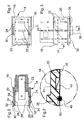
- Figure 1 is a sectioned view of the connection system of the invention with the first and second connector members in a coupled configuration;
- Figure 2 is an enlarged scale view of a detail of Figure 1,
- Figure 3 is a plan view of the first connector member of the system of Figure 1,
- Figure 4 is a front view of the first connector member of Figure 3,
- Figure 5 is a section taken on the line V-V of Figure 3,
- Figure 6 is a plan view of the second connector member of the system of Figure 1,
- Figure 7 is a front view of the second connector member of Figure 6, and
- Figure 8 is a section taken on the line VIII-VIII of Figure 6.
-
- A system for connecting an electric
power supply cable 10 to a domestic appliance - of which for the sake of simplicity Figure 1 shows only a portion of the casing wall 12 - includes afirst connector member 14 fixed to thewall 12 of the domestic appliance and asecond connector member 16 fixed to one end of thecable 10. - The
first connector member 14 includes (see Figures 3-5) abody 18 with acavity 20 open to the outside and withblade pins 22 protruding therein which are electrically connected in a conventional manner to the internal electrical circuit of the domestic appliance. - The
cavity 20 is substantially rectangular in shape with first andsecond notches 24 in two opposite walls respectively and acontinuous groove 26 formed in a plane substantially parallel to themouth 28 of thecavity 20. - Outside the
mouth 28, thebody 18 has first andsecond projections 30 facing each other and each having asurface 32 inclined towards themouth 28 and terminating in agroove 34 parallel to themouth 28. - Thanks to the
inclined surfaces 32 and thegrooves 34, thefirst connector member 14 can be snap engaged (Figure 1) in an appropriately shapedopening 36 in thewall 12 of the domestic appliance. - The
second connector member 16 includes (Figures 6-8) abody 38 in which is embedded thebase 40 of anextension 42 having a projectingportion 44 of a substantially rectangular shape complementary to that of thecavity 20 in thefirst connector member 14 and having first and second wedge-shaped formations 46 on two respective opposite surfaces. Acontinuous groove 48 is also formed in the outer surface of the projectingportion 44, with asealing ring 50 housed therein as shown in Figure 1. - Also embedded in the
body 38 is one end of anelectricity cable 52 withwires 54 withelectrical terminals 56 protruding therefrom and connected tohollow seats 58 formed in theextension 42, as well as afilter 60 connected to thewires 54. - In dependence on the requirements of each application, the
filter 60 can include various resistor, capacitor or inductor components, thereby being operable to eliminate any electromagnetic disturbances originating either from the power network or from the appliance. In alternative embodiments of the invention, not shown in the drawings, thefilter 60 could also be associated with thefirst connector member 14 instead of thesecond member 16. - In order to couple together the
connectors cable 10 to the domestic appliance, one need only (see Figures 1-2) insert the projectingportion 44 of theextension 42 of thesecond member 16 into thecomplementary cavity 20 in thefirst member 14, taking advantage of the resilience of the walls of the latter, until the wedge-shaped formations 46 engage therespective notches 24. The wedge-shaped formations 46 and thenotches 24 act as retaining means, holding themembers cable 10 by specialist technical personnel. - In the coupled configuration, the
blade pins 22 of thefirst connector 14 penetrate into thehollow seats 58 formed in theextension 42 of thesecond member 16, thereby ensuring electrical continuity between theelectric supply cable 10 and the internal electrical circuit of the domestic appliance. Meanwhile, theseal 50 is housed in the two facinggrooves cavity 20. In addition, the front surface of themember 16 is in contact with thewall 12 and has cavities for housing theprojections 30 of thebody 18 of theconnector 14, thus making sure that the connection is watertight. - It is advantageous if the
members cable 10 separate during the production cycle and during transport, storage and delivery to a customer, thereby simplifying the logistics of these operations. - Naturally, the principle of the invention remaining unchanged, embodiments and manufacturing details may vary widely from those described and illustrated purely by way of non-limitative example, without departing thereby from the scope of the invention. For example, the shape of the connector members, and in particular of the retaining means, may vary at will, provided they can still engage with each other. Furthermore, an electronic interface, operable to exchange data with the control unit of the domestic appliance, could be integrated into one of the connectors.
Claims (14)
- A system for connecting an electric power supply cable (10) to a domestic appliance, which includes a first connector member (14) fixed to the said domestic appliance in such a way that it is accessible from the outside and connected electrically to the electrical circuit inside the appliance, and a second connector member (16) fixed to one end of the said cable (10), the said first and second connector members (14, 16) being connectable together to ensure electrical continuity between the electric power supply cable (10) and the electrical circuit inside the appliance and having retaining means for holding them together once they are coupled and for preventing them from being separated as a result of forces exerted manually.
- A system according to Claim 1, in which the said first connector member (14) includes a body (18) having a cavity (20) open to the outside with blade pins (22) protruding therein which are connected electrically to the internal electrical circuit of the appliance, at least one notch (24) being formed in the walls of the said cavity (20).
- A system according to Claim 2, in which, outside the mouth (28) of the cavity (20), the said body (18) has first and second projections (30) facing each other and having a surface (32) inclined towards the mouth (28) and terminating in a groove (34) parallel to the said mouth (28).
- A system according to Claims 2 or 3, in which the shape of the said cavity (20) is substantially rectangular and it has first and second notches (24) in respective opposite walls.
- A system according to any of Claims 2 to 4, in which a continuous groove (26), substantially parallel to the mouth (28) of the cavity (20), is formed in the inner wall of the said cavity (20) .
- A system according to any preceding Claim, in which a filter operable to eliminate electromagnetic disturbances is fitted in the body (18) of the first connector member (14).
- A system according to any Claim from 2 to 6, in which the said second connector member (16) includes a body (38) in which is embedded the base (40) of an extension (42) with a projecting portion (44) of a shape complementary to that of the cavity (20) of the first connector member (14) and having at least one wedge-shape formation (46) on its outer surface, for engaging in the said notch (24) in the cavity (20).
- A system according to Claim 7, in which the said projecting portion (44) is of a substantially rectangular shape and has first and second wedge-shape formations (46) on two respective opposite surfaces.
- A system according to Claim 7 or Claim 8, in which a continuous groove (48) is formed in the outer surface of the said projecting portion (44) for housing a seal (50).
- A system according to any of Claims 7 to 9, in which one end (52) of an electric power supply cable (10) is embedded in the body (38) of the second connector member (16) with wires (54) extending therefrom having electrical terminals (56) connected to hollow seats (58) in the said extension (42) and engageable with the said blade pins (22) of the first connector member (14).
- A system according to any of Claims 7 to 10, in which a filter (60), connected to the said wires (54) and operable to eliminate electromagnetic disturbance, is embedded in the body (38) of the second connector member (16).
- A system according to any preceding Claim, in which one of the said connector members (14, 16) has an integrated electronic interface.
- A domestic appliance which includes a first connector member (14) of a connection system according to any preceding Claim.
- An electric supply cable (10) which includes a second connector member (16) of a connection system according to any of Claims from 1 to 12.
Priority Applications (1)
| Application Number | Priority Date | Filing Date | Title |
|---|---|---|---|
| EP02425462A EP1383207A1 (en) | 2002-07-15 | 2002-07-15 | A system for connecting an electric power supply cable to a domestic appliance |
Applications Claiming Priority (1)
| Application Number | Priority Date | Filing Date | Title |
|---|---|---|---|
| EP02425462A EP1383207A1 (en) | 2002-07-15 | 2002-07-15 | A system for connecting an electric power supply cable to a domestic appliance |
Publications (1)
| Publication Number | Publication Date |
|---|---|
| EP1383207A1 true EP1383207A1 (en) | 2004-01-21 |
Family
ID=29762763
Family Applications (1)
| Application Number | Title | Priority Date | Filing Date |
|---|---|---|---|
| EP02425462A Withdrawn EP1383207A1 (en) | 2002-07-15 | 2002-07-15 | A system for connecting an electric power supply cable to a domestic appliance |
Country Status (1)
| Country | Link |
|---|---|
| EP (1) | EP1383207A1 (en) |
Cited By (2)
| Publication number | Priority date | Publication date | Assignee | Title |
|---|---|---|---|---|
| WO2005071802A1 (en) * | 2004-01-22 | 2005-08-04 | Seeff, Stanley, Joseph, | Domestic electrical appliances |
| EP2110897A1 (en) * | 2008-04-17 | 2009-10-21 | Weidmüller Interface GmbH & Co. KG | Connector |
Citations (3)
| Publication number | Priority date | Publication date | Assignee | Title |
|---|---|---|---|---|
| US5454729A (en) * | 1994-03-07 | 1995-10-03 | Wen-Te; Chuang | Electric plug and socket connecting mechanism |
| DE19737500A1 (en) * | 1997-08-28 | 1999-03-04 | Philips Patentverwaltung | Electrical appliance lead cable plug |
| US6392554B1 (en) * | 2000-09-16 | 2002-05-21 | Beom Jae Lee | Electromagnetic wave isolation apparatus for use in multi-outlets |
-
2002
- 2002-07-15 EP EP02425462A patent/EP1383207A1/en not_active Withdrawn
Patent Citations (3)
| Publication number | Priority date | Publication date | Assignee | Title |
|---|---|---|---|---|
| US5454729A (en) * | 1994-03-07 | 1995-10-03 | Wen-Te; Chuang | Electric plug and socket connecting mechanism |
| DE19737500A1 (en) * | 1997-08-28 | 1999-03-04 | Philips Patentverwaltung | Electrical appliance lead cable plug |
| US6392554B1 (en) * | 2000-09-16 | 2002-05-21 | Beom Jae Lee | Electromagnetic wave isolation apparatus for use in multi-outlets |
Cited By (2)
| Publication number | Priority date | Publication date | Assignee | Title |
|---|---|---|---|---|
| WO2005071802A1 (en) * | 2004-01-22 | 2005-08-04 | Seeff, Stanley, Joseph, | Domestic electrical appliances |
| EP2110897A1 (en) * | 2008-04-17 | 2009-10-21 | Weidmüller Interface GmbH & Co. KG | Connector |
Similar Documents
| Publication | Publication Date | Title |
|---|---|---|
| EP3700025B1 (en) | Sealed electric plug | |
| CN100524969C (en) | Electric connector for charging cellular telephone | |
| CN114127881B (en) | Base, circuit breaker and power distribution equipment with base | |
| CN105706305B (en) | Bridge module for special-shaped mounting rail | |
| CN102437449A (en) | Electric connector | |
| CN103579789A (en) | Adapter for connecting a harness to magnet wires | |
| CN107002444A (en) | Construction unit with the glass carrier for vehicle glass | |
| EP1187259A3 (en) | Electrical connection box for a vehicle | |
| EP0818356B1 (en) | Electrical connection box for use in a car | |
| US4789361A (en) | Fused cigarette lighter receptacle and adaptor plug assemblies | |
| US20190288460A1 (en) | Plug | |
| US3355630A (en) | Meter structure with imbedded bus bars and jaw mounting structure | |
| US7479047B2 (en) | Assembly for connecting the stator windings of an electric motor to the respective power supply | |
| US20200080770A1 (en) | Electrical appliance having electric devices in a distributed arrangement | |
| CN108448823A (en) | A kind of pump assembly | |
| CN101142650A (en) | Switchable power distribution blocks with fuses | |
| EP2053322B1 (en) | Assembly for electrical connection, start on and protection of an electric moto-compressor sealed in hermetic metal shell | |
| US6458000B2 (en) | Power connector ground polarization insert and connector used therewith | |
| KR200461550Y1 (en) | Wire harness connector housing for stable pin connection | |
| CN220627628U (en) | Expansion module and dual-power transfer switch | |
| US6943661B2 (en) | Quick-connect positive temperature coefficient of resistance resistor/overload assembly and method | |
| EP1220357A3 (en) | Electrical connection box | |
| JPH08335476A (en) | Connector | |
| US6252491B1 (en) | Plug for an appliance having a fuse | |
| KR101151896B1 (en) | Wire connecting device |
Legal Events
| Date | Code | Title | Description |
|---|---|---|---|
| PUAI | Public reference made under article 153(3) epc to a published international application that has entered the european phase |
Free format text: ORIGINAL CODE: 0009012 |
|
| AK | Designated contracting states |
Kind code of ref document: A1 Designated state(s): AT BE BG CH CY CZ DE DK EE ES FI FR GB GR IE IT LI LU MC NL PT SE SK TR |
|
| AX | Request for extension of the european patent |
Extension state: AL LT LV MK RO SI |
|
| RIN1 | Information on inventor provided before grant (corrected) |
Inventor name: EVANGELISTI, PIER GOTTARDO |
|
| AKX | Designation fees paid | ||
| REG | Reference to a national code |
Ref country code: DE Ref legal event code: 8566 |
|
| STAA | Information on the status of an ep patent application or granted ep patent |
Free format text: STATUS: THE APPLICATION IS DEEMED TO BE WITHDRAWN |
|
| 18D | Application deemed to be withdrawn |
Effective date: 20040722 |