EP1383028A2 - A computer system having interchangeable LCDs - Google Patents
A computer system having interchangeable LCDs Download PDFInfo
- Publication number
- EP1383028A2 EP1383028A2 EP03251132A EP03251132A EP1383028A2 EP 1383028 A2 EP1383028 A2 EP 1383028A2 EP 03251132 A EP03251132 A EP 03251132A EP 03251132 A EP03251132 A EP 03251132A EP 1383028 A2 EP1383028 A2 EP 1383028A2
- Authority
- EP
- European Patent Office
- Prior art keywords
- main housing
- computer system
- display
- lcd
- parts
- Prior art date
- Legal status (The legal status is an assumption and is not a legal conclusion. Google has not performed a legal analysis and makes no representation as to the accuracy of the status listed.)
- Ceased
Links
Images



Classifications
-
- G—PHYSICS
- G06—COMPUTING OR CALCULATING; COUNTING
- G06F—ELECTRIC DIGITAL DATA PROCESSING
- G06F1/00—Details not covered by groups G06F3/00 - G06F13/00 and G06F21/00
- G06F1/16—Constructional details or arrangements
-
- G—PHYSICS
- G06—COMPUTING OR CALCULATING; COUNTING
- G06F—ELECTRIC DIGITAL DATA PROCESSING
- G06F1/00—Details not covered by groups G06F3/00 - G06F13/00 and G06F21/00
- G06F1/16—Constructional details or arrangements
- G06F1/1601—Constructional details related to the housing of computer displays, e.g. of CRT monitors, of flat displays
-
- G—PHYSICS
- G06—COMPUTING OR CALCULATING; COUNTING
- G06F—ELECTRIC DIGITAL DATA PROCESSING
- G06F2200/00—Indexing scheme relating to G06F1/04 - G06F1/32
- G06F2200/16—Indexing scheme relating to G06F1/16 - G06F1/18
- G06F2200/161—Indexing scheme relating to constructional details of the monitor
- G06F2200/1612—Flat panel monitor
-
- G—PHYSICS
- G06—COMPUTING OR CALCULATING; COUNTING
- G06F—ELECTRIC DIGITAL DATA PROCESSING
- G06F2200/00—Indexing scheme relating to G06F1/04 - G06F1/32
- G06F2200/16—Indexing scheme relating to G06F1/16 - G06F1/18
- G06F2200/163—Indexing scheme relating to constructional details of the computer
- G06F2200/1631—Panel PC, e.g. single housing hosting PC and display panel
Definitions
- the present invention relates to a method for changing the display of an all-in-one computer system comprising a main housing covering a main board and having fixing means fixing a display thereto, the method comprising, detaching said display from said main housing, and attaching another display to said main housing by said fixing means.
- the present invention also relates to a collection of components for the formation of at least one all-in-one computer system, the collection comprising a main housing for covering a main board and having fixing means for fixing a display thereto; and first and second displays configured for being attached to the main housing by said fixing means.
- a computer system includes a main body having a plurality of hardware components such as a main board equipped with a CPU (central processing unit), a hard disk drive, a graphic card, a floppy disk drive, a CD (compact disk) drive, etc.
- a computer system also includes a monitor that receives a video signal from the main body and displays a picture, and an input unit such as a keyboard, a mouse, etc., to input a predetermined signal to the main body.
- a computer system is classified as a notebook computer system, a desktop computer system, etc.
- a notebook computer system is relatively slim and light due to its LCD monitor (hereinafter referred to as "LCD display part"), and is typically employed as a portable computer.
- LCD display part LCD monitor
- a desktop computer system is typically designed for use on a desk or a table.
- desktop computer systems are generally larger in size than notebook computer systems, a desktop computer system occupies a larger space than a notebook computer system.
- LCD display parts have been widely used in desktop computer systems instead of CRT monitors, so that the space occupied by a desktop computer system is decreased.
- a desktop computer system still requires a relatively large space for the installation of a main body and a monitor in comparison with that of a notebook computer system. Accordingly, in order to decrease the space occupied by a desktop computer system, there has been proposed a computer in which an LCD display part and a main body are formed as a single body.
- Such a computer system is generally known as an "all-in-one" computer system.
- a conventional computer system 100 includes a front cover 110, a main housing 130 to form a predetermined space by combining with the front cover 110, an LCD display part (not shown) including an LCD panel (not shown) on which a picture is displayed, a PCB (Printed Circuit Board) assembly (not shown) to transmit a video signal to the LCD panel, and a main board (not shown) to control the computer system 100.
- an LCD display part including an LCD panel (not shown) on which a picture is displayed
- a PCB (Printed Circuit Board) assembly (not shown) to transmit a video signal to the LCD panel
- main board not shown
- the front cover 110 has an opening through which the LCD panel is exposed, and is placed in front of the LCD panel to cover peripheral edges of the LCD panel.
- the main housing 130 is backwardly recessed to form an accommodating space to accommodate a main board.
- the PCB assembly converts a predetermined signal received from the main board into a video signal, and transmits the video signal to the LCD panel.
- the main board is mounted with a CPU, a graphic card, a sound card, etc., and operates the computer system 100 depending upon electric power supplied from a power supply (not shown).
- a conventional computer system 100 is assembled as follows. First, the main board is accommodated in the accommodating space of the main housing 130, and fastened to the main housing 130 with screws (not shown). Thereafter, the hardware components including the main board, the LCD display part, etc., are electrically connected to each other, and then the front cover 110 and the main housing 130 are combined by screws 150, thereby completing the assembly of the computer system 100.
- an object of the present invention to provide a computer system in which an LCD display part is easily disassembled and easily replaced with different sizes of LCD display parts.
- a method for changing the display of an all-in-one computer system characterised in that said first and second displays are of different sizes.
- the method includes removing said main board from the replaced display after it has been detached from the main housing and mounting the main board to the replacing display before it is attached to the main housing.
- said first and second displays comprise main board mounting means for releasably mounting said main board on the rear thereof.
- said main housing comprises a box-like member which has an opening at the front, said opening being closed by the attachment of one of said first or second displays thereto.
- said first and second displays comprise liquid crystal display panels.
- a computer system includes first and second LCD display parts 10a and 10b, each having connecting elements (or main housing mounting parts) 14 arranged at the same intervals.
- the computer system also includes a main housing 30 to accommodate a main board 50 therein, and to selectively combine with one of the first and second LCD display parts 10a and 10b via the connecting elements 14.
- the first and second LCD display parts 10a and 10b include LCD panels (not shown) to display a picture thereon, PCB assemblies (not shown) to transmit a video signal to the LCD panel, supporting members 17a and 17b to support the LCD panels, front casings 12a and 12b placed in front of the LCD panels to cover peripheral edges of the LCD panel, and rear casings 13a and 13b to form predetermined spaces by combining with the front casings 12a and 12b, respectively.
- the LCD panel changes the molecular arrangement of a liquid crystal thereof when electric power is supplied thereto and interrupts transmission of light to form a picture.
- the size of an LCD display part is determined according to a diagonal length of the LCD panel.
- the PCB assembly is disposed behind the LCD panel, and is provided with an inverter board, a scaler board, an OSD (On Screen Display) board, etc.
- the PCB assembly converts a predetermined signal received from the main board 50 (to be described later) into a video signal, and transmits it to the LCD panel.
- the PCB assembly has different components according to the sizes of the LCD display parts 10a and 10b.
- the first and second LCD display parts 10a and 10b are each equipped with different PCB assemblies.
- the supporting members 17a and 17b are disposed behind the PCB assembly, which is disposed behind the LCD panel, to support the LCD panel and the PCB assembly.
- the front casings 12a and 12b have openings (not shown) through which the respective LCD panels are exposed, and cover the peripheral edges of the LCD panels.
- the front casings 12a and 12b are combined with the rear casings 13a and 13b (to be described later) by bolts 71 to form an accommodating space to accommodate the LCD panels.
- Connecting elements 14 project from the back of the first and second LCD display parts 10a and 10b, so that the first and second LCD display parts 10a and 10b can be selectively combined with the main housing 30.
- the connecting elements 14 include tabs (or screw combining arms) 14b, and the main housing 30 includes a plurality of screw holes 34 to correspond to the tabs 14b, so that the first and second LCD display parts 10a and 10b can be selectively combined with the main housing 30 by first screws 72.
- the tabs 14b of the first and second LCD display parts 10a and 10b protrude from side edges of the supporting members 17a and 17b toward the main housing 30.
- the tabs 14b are formed with through holes 14a.
- the screw holes 34 of the main housing 30 are formed in groove parts 33 of the main housing 30 to receive the tabs 14b, and correspond to the through holes 14a.
- the tabs 14b are arranged at opposite sides of the rear of LCD display part 10a or 10b, so as to evenly support the load of the LCD display part 10a or 10b.
- the first and second LCD display parts 10a and 10b are provided with a plurality of hook holders 35 arranged at the same intervals above the supporting members 17a and 17b.
- the main housing 30 is provided with a plurality of hooks 15 to be engaged with the hook holders 35.
- the hooks 15 are, as shown in Figure 3, provided in an upper part of the main housing 30. However, the hooks 15 may be provided on opposite sides of the main housing 30, with the hook holders 35 being provided on the rear of the LCD display part 10a and 10b to correspond to the hooks 15.
- first and second LCD display parts 10a and 10b are provided with main board mounting parts for the main board 50.
- the main board mounting parts include a plurality of screw holes 16 which are arranged at the same intervals in the supporting members 17a and 17b.
- a plurality of second screws 73 are provided to go through through holes 56 formed on the main board 50, and are inserted into the screw holes 16 so that the main board 50 is mounted to the rear of the LCD display part 10a or 10b.
- the same main board 50 may be mounted to either one of the first and second LCD display parts 10a and 10b.
- the connecting elements 14 include the tabs 14b so as to selectively combine the LCD display parts 10a and 10b with the main housing 30 by first screws 72.
- the connecting elements 14 may include a plurality of locking members such as hooks, etc., so as to selectively combine the LCD display part 10a and 10b with the main housing 30 without screws.
- the LCD display parts 10a and 10b which are different in size are provided with similar connecting elements 14. Therefore, the LCD display part 10a and 10b is easily separated from the main housing 30, and the main housing 30 is selectively combined with one of the first and second LCD display parts 10a and 10b, which are different in size. Thus, the LCD display part 10a and 10b of the computer system according to the present invention is easily replaceable.
Landscapes
- Engineering & Computer Science (AREA)
- Theoretical Computer Science (AREA)
- General Engineering & Computer Science (AREA)
- Human Computer Interaction (AREA)
- Physics & Mathematics (AREA)
- General Physics & Mathematics (AREA)
- Computer Hardware Design (AREA)
- Devices For Indicating Variable Information By Combining Individual Elements (AREA)
- Liquid Crystal (AREA)
Abstract
Description
- The present invention relates to a method for changing the display of an all-in-one computer system comprising a main housing covering a main board and having fixing means fixing a display thereto, the method comprising, detaching said display from said main housing, and attaching another display to said main housing by said fixing means. The present invention also relates to a collection of components for the formation of at least one all-in-one computer system, the collection comprising a main housing for covering a main board and having fixing means for fixing a display thereto; and first and second displays configured for being attached to the main housing by said fixing means.
- Generally, a computer system includes a main body having a plurality of hardware components such as a main board equipped with a CPU (central processing unit), a hard disk drive, a graphic card, a floppy disk drive, a CD (compact disk) drive, etc. A computer system also includes a monitor that receives a video signal from the main body and displays a picture, and an input unit such as a keyboard, a mouse, etc., to input a predetermined signal to the main body.
- A computer system is classified as a notebook computer system, a desktop computer system, etc. A notebook computer system is relatively slim and light due to its LCD monitor (hereinafter referred to as "LCD display part"), and is typically employed as a portable computer. A desktop computer system is typically designed for use on a desk or a table.
- Because desktop computer systems are generally larger in size than notebook computer systems, a desktop computer system occupies a larger space than a notebook computer system. Recently, LCD display parts have been widely used in desktop computer systems instead of CRT monitors, so that the space occupied by a desktop computer system is decreased. However, a desktop computer system still requires a relatively large space for the installation of a main body and a monitor in comparison with that of a notebook computer system. Accordingly, in order to decrease the space occupied by a desktop computer system, there has been proposed a computer in which an LCD display part and a main body are formed as a single body. Such a computer system is generally known as an "all-in-one" computer system.
- Referring to Figure 1, a
conventional computer system 100 includes afront cover 110, amain housing 130 to form a predetermined space by combining with thefront cover 110, an LCD display part (not shown) including an LCD panel (not shown) on which a picture is displayed, a PCB (Printed Circuit Board) assembly (not shown) to transmit a video signal to the LCD panel, and a main board (not shown) to control thecomputer system 100. - The
front cover 110 has an opening through which the LCD panel is exposed, and is placed in front of the LCD panel to cover peripheral edges of the LCD panel. Themain housing 130 is backwardly recessed to form an accommodating space to accommodate a main board. - The PCB assembly converts a predetermined signal received from the main board into a video signal, and transmits the video signal to the LCD panel. The main board is mounted with a CPU, a graphic card, a sound card, etc., and operates the
computer system 100 depending upon electric power supplied from a power supply (not shown). - In accordance with the configuration as described above, a
conventional computer system 100 is assembled as follows. First, the main board is accommodated in the accommodating space of themain housing 130, and fastened to themain housing 130 with screws (not shown). Thereafter, the hardware components including the main board, the LCD display part, etc., are electrically connected to each other, and then thefront cover 110 and themain housing 130 are combined byscrews 150, thereby completing the assembly of thecomputer system 100. - However, in a
conventional computer system 100, because the LCD display part and the main board are disposed between thefront cover 110 and themain housing 130, and thefront cover 110 and themain housing 130 are combined by thescrews 150, it is not easy to disassemble thecomputer system 100. Further, it becomes difficult to replace the LCD display part with different sizes of LCD display parts. - Accordingly, it is an object of the present invention to provide a computer system in which an LCD display part is easily disassembled and easily replaced with different sizes of LCD display parts.
- According to the present invention, there is provided, a method for changing the display of an all-in-one computer system characterised in that said first and second displays are of different sizes.
- Preferably, the method includes removing said main board from the replaced display after it has been detached from the main housing and mounting the main board to the replacing display before it is attached to the main housing.
- According to the present invention, there is provided, a collection of components for the formation of at least one all-in-one computer system, characterised in that the displays are of different sizes.
- Preferably, said first and second displays comprise main board mounting means for releasably mounting said main board on the rear thereof.
- Preferably, said main housing comprises a box-like member which has an opening at the front, said opening being closed by the attachment of one of said first or second displays thereto.
- Preferably, said first and second displays comprise liquid crystal display panels.
- An embodiment of the present invention will now be described, by way of example, in reference to the Figures 2a to 3, in which:
- Figure 1 is a rear perspective view of a conventional computer system;
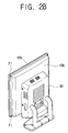
- Figure 2a is a rear perspective view of a computer system equipped with a first LCD display part, according to an embodiment of the present invention;
- Figure 2b is a rear perspective view of the computer system equipped with a second LCD display part; and
- Figure 3 is an exploded perspective view of the computer system according to the present invention.
-
- Referring to Figures 2a, 2b and 3, a computer system according to the present invention includes first and second
LCD display parts main housing 30 to accommodate amain board 50 therein, and to selectively combine with one of the first and secondLCD display parts elements 14. - The first and second
LCD display parts members front casings rear casings front casings - The LCD panel changes the molecular arrangement of a liquid crystal thereof when electric power is supplied thereto and interrupts transmission of light to form a picture. Generally, the size of an LCD display part is determined according to a diagonal length of the LCD panel.
- The PCB assembly is disposed behind the LCD panel, and is provided with an inverter board, a scaler board, an OSD (On Screen Display) board, etc. The PCB assembly converts a predetermined signal received from the main board 50 (to be described later) into a video signal, and transmits it to the LCD panel. The PCB assembly has different components according to the sizes of the
LCD display parts LCD display parts - The supporting
members - The
front casings front casings rear casings bolts 71 to form an accommodating space to accommodate the LCD panels. - Connecting
elements 14 project from the back of the first and secondLCD display parts LCD display parts main housing 30. The connectingelements 14 include tabs (or screw combining arms) 14b, and themain housing 30 includes a plurality ofscrew holes 34 to correspond to thetabs 14b, so that the first and secondLCD display parts main housing 30 byfirst screws 72. - The
tabs 14b of the first and secondLCD display parts members main housing 30. Thetabs 14b are formed with throughholes 14a. Thescrew holes 34 of themain housing 30 are formed in groove parts 33 of themain housing 30 to receive thetabs 14b, and correspond to the throughholes 14a. Thus, when theLCD display part main housing 30, thetabs 14b thereof are each inserted into the groove parts 33, thereby settling theLCD display part main housing 30. Thetabs 14b are arranged at opposite sides of the rear ofLCD display part LCD display part - Furthermore, the first and second
LCD display parts hook holders 35 arranged at the same intervals above the supportingmembers main housing 30 is provided with a plurality ofhooks 15 to be engaged with thehook holders 35. Thus, when theLCD display part main housing 30, theLCD display part main housing 30 by the engagement of thehook holders 35 and thehooks 15 before being fastened with thefirst screws 72. - The
hooks 15 are, as shown in Figure 3, provided in an upper part of themain housing 30. However, thehooks 15 may be provided on opposite sides of themain housing 30, with thehook holders 35 being provided on the rear of theLCD display part hooks 15. - Furthermore, the first and second
LCD display parts main board 50. The main board mounting parts include a plurality ofscrew holes 16 which are arranged at the same intervals in the supportingmembers second screws 73 are provided to go through throughholes 56 formed on themain board 50, and are inserted into thescrew holes 16 so that themain board 50 is mounted to the rear of theLCD display part LCD display part main board 50 may be mounted to either one of the first and secondLCD display parts - In the foregoing embodiment, the connecting
elements 14 include thetabs 14b so as to selectively combine theLCD display parts main housing 30 byfirst screws 72. However, the connectingelements 14 may include a plurality of locking members such as hooks, etc., so as to selectively combine theLCD display part main housing 30 without screws. - As described above, the
LCD display parts elements 14. Therefore, theLCD display part main housing 30, and themain housing 30 is selectively combined with one of the first and secondLCD display parts LCD display part
Claims (28)
- A method for changing the display of an all-in-one computer system comprising a main housing (30) covering a main board (50) and having fixing means (34) fixing a display (10a) thereto, the method comprising, detaching said display (10a) from said main housing (30), and attaching another display (10b) to said main housing (30) by said fixing means (34), characterised in that said first and second displays (10a, 10b) are of different sizes.
- A method according to claim 1, including removing said main board (50) from the replaced display (10a) after it has been detached from the main housing (30) and mounting the main board (50) to the replacing display (10b) before it is attached to the main housing (30).
- A collection of components for the formation of at least one all-in-one computer system, the collection comprising a main housing (30) for covering a main board (50) and having fixing means (34) for fixing a display thereto; and first and second displays (10a, 10b) configured for being attached to the main housing (30) by said fixing means (34), characterised in that the displays (10a, 10b) are of different sizes.
- A collection according to claim 3, wherein said first and second displays (10a, 10b) comprise main board mounting means (16) for releasably mounting said main board (50) on the rear thereof.
- A collection according to claim 3 or 4, wherein said main housing (30) comprises a box-like member which has an opening at the front, said opening being closed by the attachment of one of said first or second displays (10a, 10b) thereto.
- A collection according to claim 3, 4 or 5, wherein said first and second displays (10a, 10b) comprise liquid crystal display panels.
- A computer system, comprising:wherein different sizes of LCD display parts are selectively combined with the main housing to be replaceable.an LCD (Liquid Crystal Display) display part provided with a main housing mounting part in a rear thereof; anda main housing to accommodate a main board, and detachably combined with the main housing mounting part of the LCD display part,
- The computer system according to claim 7, wherein the LCD display parts include main board mounting parts, each having the same combining structures to combine with the main board.
- The computer system according to claim 7, wherein the main housing mounting part comprises a plurality of screw combining arms, and the main housing is provided with a plurality of screw holes corresponding to the screw combining arms.
- The computer system according to claim 9, wherein the LCD display parts comprises a plurality of hook holders at the rear thereof, and the main housing is provided with a plurality of hooks engaged with the hook holders.
- The computer system according to claim 10, wherein the LCD display parts include:an LCD panel to display a picture thereon;a PCB (Printed Circuit Board) assembly to transmit a video signal to the LCD panel;a supporting member to support the LCD panel, and provided with the screw combining arms;a front casing disposed in front of the LCD panel, to cover front edges of the LCD panel; anda rear casing to form a predetermined housing by combining with the front casing.
- The computer system according to claim 11, wherein the hook holders are formed on the rear casing.
- The computer system according to claim 11, wherein the supporting member is disposed behind the PCB assembly, which is disposed by the LCD panel, to support the PCB assembly and the LCD panel.
- The computer system according to claim 9, wherein the screw holes of the main housing are provided in groove parts on sides of the main housing to receive the screw combining arms of the main housing mounting part.
- The computer system according to claim 14, wherein the screw combining arms of the main housing mounting part are inserted to the groove parts of the main housing to settle the LCD display parts in a combining position of the main housing.
- The computer system according to claim 7, wherein the main housing mounting part is provided with a plurality of locking members to combine the LCD display parts with the main housing.
- A computer system, comprising:a plurality of LCD (Liquid Crystal Display) display parts different in size, and provided with similar main housing mounting parts; anda main housing provided with a display mounting part corresponding to the main housing mounting part, to which one of the LCD display parts is selectively combined.
- The computer system according to claim 17, wherein the plurality of LCD display parts include main board mounting parts having similar structures to combine with a main board received in the main housing.
- The computer system according to claim 17, wherein the main housing mounting part comprises a plurality of screw combining arms, and the display mounting part comprises a plurality of screw holes corresponding to the screw combining arms.
- The computer system according to claim 19, wherein the main housing mounting part comprises a plurality of hook holders, and the display mounting part comprises hooks protruding toward the LCD display parts to be engaged with the hook holders.
- The computer system according to claim 19, wherein the LCD display parts include:an LCD panel to display a picture thereon;a PCB (Printed Circuit Board) assembly to transmit a video signal to the LCD panel;a supporting member to support the LCD panel, and provided with the screw combining arms;a front casing disposed in front of the LCD panel, to cover front edges of the LCD panel; anda rear casing to form a predetermined housing by combining with the front casing.
- The computer system according to claim 20, wherein the LCD display parts include:an LCD panel to display a picture thereon;a PCB assembly to transmit a video signal to the LCD panel;a supporting member to support the LCD panel, and provided with the screw combining arms;a front casing disposed in front of the LCD panel, to cover front edges of the LCD panel; anda rear casing to form a predetermined housing by combining with the front casing.
- The computer system according to claim 21, wherein the supporting member is disposed behind the PCB assembly, which is disposed by the LCD panel, to support the PCB assembly and the LCD panel.
- The computer system according to claim 19, wherein the screw holes of the main housing are provided in groove parts on sides of the main housing to receive the screw combining arms of the main housing mounting part.
- The computer system according to claim 24, wherein the screw combining arms of the main housing mounting part are inserted to the groove parts of the main housing to selectively settle the LCD display parts in a combining position of the main housing.
- The computer system according to claim 17, wherein the main housing mounting part is provided with a plurality of locking members to selectively combine the LCD display parts with the main housing.
- A method of manufacturing a computer system, comprising:providing similar main housing mounting parts to rears of a plurality of LCD (Liquid Crystal Display) display parts different in size from each other; andproviding a display mounting part to a main housing, which is combined to each of the main housing mounting parts so as to selectively combine one of the plurality of LCD display parts to the main housing.
- A computer system, comprising;a plurality of LCD (Liquid Crystal Display) display parts, interchangeable and provided with similar main housing mounting parts; anda main housing provided with a display mounting part corresponding to the main housing mounting part, to selectively combine with the LCD display parts.
Applications Claiming Priority (2)
| Application Number | Priority Date | Filing Date | Title |
|---|---|---|---|
| KR10-2002-0037975A KR100476085B1 (en) | 2002-07-02 | 2002-07-02 | Computer System |
| KR2002037975 | 2002-07-02 |
Publications (2)
| Publication Number | Publication Date |
|---|---|
| EP1383028A2 true EP1383028A2 (en) | 2004-01-21 |
| EP1383028A3 EP1383028A3 (en) | 2006-06-07 |
Family
ID=36648912
Family Applications (1)
| Application Number | Title | Priority Date | Filing Date |
|---|---|---|---|
| EP03251132A Ceased EP1383028A3 (en) | 2002-07-02 | 2003-02-25 | A computer system having interchangeable LCDs |
Country Status (6)
| Country | Link |
|---|---|
| US (1) | US7233486B2 (en) |
| EP (1) | EP1383028A3 (en) |
| JP (1) | JP2004038920A (en) |
| KR (1) | KR100476085B1 (en) |
| CN (1) | CN1253771C (en) |
| TW (1) | TWI235947B (en) |
Cited By (2)
| Publication number | Priority date | Publication date | Assignee | Title |
|---|---|---|---|---|
| GB2431867A (en) * | 2005-11-02 | 2007-05-09 | Discount Comp Supplies Ltd | A digital display accessory |
| ITBO20130475A1 (en) * | 2013-09-06 | 2015-03-07 | Michele Cestari | COMPUTER |
Families Citing this family (44)
| Publication number | Priority date | Publication date | Assignee | Title |
|---|---|---|---|---|
| US8934226B2 (en) * | 2004-03-08 | 2015-01-13 | Originatic Llc | Mountable device having a pivotable input device support |
| TWI247250B (en) * | 2004-11-05 | 2006-01-11 | Hon Hai Prec Ind Co Ltd | A display device with a skin including a controller and an OSD unit |
| CN2812226Y (en) * | 2005-08-02 | 2006-08-30 | 广州矽金塔电子有限公司 | Supporting & fixing structure for portable visual electronic product |
| US7496627B2 (en) * | 2006-03-16 | 2009-02-24 | Exceptional Innovation, Llc | Automation control system having digital logging |
| WO2007109558A2 (en) * | 2006-03-16 | 2007-09-27 | Exceptional Innovation, Llc | Network based digital access point device |
| US8209398B2 (en) | 2006-03-16 | 2012-06-26 | Exceptional Innovation Llc | Internet protocol based media streaming solution |
| US8725845B2 (en) | 2006-03-16 | 2014-05-13 | Exceptional Innovation Llc | Automation control system having a configuration tool |
| US7509402B2 (en) | 2006-03-16 | 2009-03-24 | Exceptional Innovation, Llc | Automation control system having a configuration tool and two-way ethernet communication for web service messaging, discovery, description, and eventing that is controllable with a touch-screen display |
| US8155142B2 (en) | 2006-03-16 | 2012-04-10 | Exceptional Innovation Llc | Network based digital access point device |
| US7587464B2 (en) * | 2006-03-16 | 2009-09-08 | Exceptional Innovation, Llc | Device automation using networked device control having a web services for devices stack |
| US8001219B2 (en) | 2006-03-16 | 2011-08-16 | Exceptional Innovation, Llc | User control interface for convergence and automation system |
| US7966083B2 (en) | 2006-03-16 | 2011-06-21 | Exceptional Innovation Llc | Automation control system having device scripting |
| WO2007126781A2 (en) | 2006-03-27 | 2007-11-08 | Exceptional Innovation Llc | Set top box for convergence and automation system |
| WO2007124453A2 (en) | 2006-04-20 | 2007-11-01 | Exceptional Innovation Llc | Touch screen for convergence and automation system |
| US20100053876A1 (en) * | 2006-04-21 | 2010-03-04 | Dreamcom Corporation | Laptop computer |
| US7667968B2 (en) | 2006-05-19 | 2010-02-23 | Exceptional Innovation, Llc | Air-cooling system configuration for touch screen |
| JP4122460B2 (en) * | 2006-05-24 | 2008-07-23 | 船井電機株式会社 | Disc device integrated liquid crystal display device |
| TWM309320U (en) * | 2006-07-14 | 2007-04-01 | Fang-Yu Jang | Frame structure |
| JP4777846B2 (en) * | 2006-08-23 | 2011-09-21 | 富士通株式会社 | Information processing device |
| US7719832B2 (en) * | 2006-10-31 | 2010-05-18 | Hewlett-Packard Development Company, L.P. | Computing device mounting system |
| US7962130B2 (en) * | 2006-11-09 | 2011-06-14 | Exceptional Innovation | Portable device for convergence and automation solution |
| JP4814761B2 (en) * | 2006-11-15 | 2011-11-16 | 光洋電子工業株式会社 | Display device with small display |
| TW200823628A (en) * | 2006-11-30 | 2008-06-01 | Visson Technologies Inc | Electronic device and computer appliance thereof |
| WO2008143881A1 (en) * | 2007-05-14 | 2008-11-27 | Exceptional Innovation, Llc | Customizable media device |
| US8686890B2 (en) * | 2007-05-25 | 2014-04-01 | Exceptional Innovation, Llc | Customizable remote control device |
| JP5201964B2 (en) * | 2007-12-03 | 2013-06-05 | 三洋電機株式会社 | Image display device |
| TW200951680A (en) * | 2008-06-04 | 2009-12-16 | Pegatron Corp | Desktop computer and manufacturing method thereof |
| US20090310293A1 (en) * | 2008-06-12 | 2009-12-17 | Datavan International Corp. | Quick-detachable mounting system |
| TWM368090U (en) * | 2009-03-06 | 2009-11-01 | Chunghwa Picture Tubes Ltd | Fixing structure of element |
| CN101930259A (en) * | 2009-06-25 | 2010-12-29 | 鸿富锦精密工业(深圳)有限公司 | Monitors and Computers |
| TWI396005B (en) * | 2009-11-06 | 2013-05-11 | Au Optronics Corp | Back cover module and assembling method thereof, backlight module and assembling method thereof, and flat panel display device and assembling method thereof |
| CN102053664A (en) * | 2009-11-09 | 2011-05-11 | 鸿富锦精密工业(深圳)有限公司 | Computer host and case thereof |
| TWM383139U (en) * | 2010-01-15 | 2010-06-21 | Pegatron Corp | All-in-one desktop computer |
| TWM384477U (en) * | 2010-01-27 | 2010-07-11 | Aopen Inc | Monitor and its outer casing structure |
| US8358395B1 (en) | 2010-03-09 | 2013-01-22 | Western Digital Technologies, Inc. | Electronic display assembly comprising a display mount and a flex circuit wrapped around and adhered to the display mount |
| CN102207748B (en) | 2010-03-31 | 2015-03-25 | 联想(北京)有限公司 | Electronic equipment and input method |
| WO2011136777A1 (en) * | 2010-04-29 | 2011-11-03 | Hewlett Packard Development Company, L.P. | Modular, all-in-one computing device |
| JP2012253094A (en) * | 2011-05-31 | 2012-12-20 | Sony Corp | Electronic apparatus |
| CN102819285B (en) * | 2011-06-08 | 2016-08-03 | 丁汀 | Computer all-in-one machine |
| JP6089637B2 (en) * | 2012-11-30 | 2017-03-08 | 船井電機株式会社 | Display device |
| CN104344442B (en) * | 2013-08-09 | 2018-09-25 | 博西华电器(江苏)有限公司 | Manufacturing method, smoke exhaust ventilator and its shell, the assembling element of casing of cooker hood |
| JP6338495B2 (en) * | 2014-09-19 | 2018-06-06 | 古野電気株式会社 | Display device and display device manufacturing method |
| KR102591766B1 (en) * | 2016-02-04 | 2023-10-23 | 삼성전자주식회사 | Connector |
| CN112879777A (en) * | 2021-03-04 | 2021-06-01 | 东莞市兴奇宏电子有限公司 | Foot seat structure of computer |
Citations (1)
| Publication number | Priority date | Publication date | Assignee | Title |
|---|---|---|---|---|
| US6188569B1 (en) | 1997-02-07 | 2001-02-13 | Hitachi, Ltd. | Information processing apparatus |
Family Cites Families (22)
| Publication number | Priority date | Publication date | Assignee | Title |
|---|---|---|---|---|
| JPH062317Y2 (en) * | 1988-08-09 | 1994-01-19 | 株式会社東芝 | Case structure |
| US5097388A (en) * | 1991-01-31 | 1992-03-17 | Unisys Corporation | Computer system housing monitor with detachable module for providing diverse functionality |
| JPH092578A (en) | 1995-06-23 | 1997-01-07 | Yutani Heavy Ind Ltd | Tank of construction machine |
| US5928320A (en) * | 1996-05-30 | 1999-07-27 | Ncr Corporation | Transaction terminal with modular display |
| JPH1069328A (en) | 1996-08-28 | 1998-03-10 | Nec Yonezawa Ltd | Notebook personal computer with projector function |
| KR100246855B1 (en) * | 1997-03-17 | 2000-03-15 | 윤종용 | LCD module of portable computer |
| KR19990005545U (en) * | 1997-07-16 | 1999-02-18 | 윤종용 | LCD display device |
| KR19990017510A (en) * | 1997-08-25 | 1999-03-15 | 윤종용 | Detachable Laptop Computer |
| US6002582A (en) * | 1998-01-05 | 1999-12-14 | Dell U.S.A., L.P. | Adapter for various LCD sizes in a computer |
| KR19990084948A (en) * | 1998-05-12 | 1999-12-06 | 윤종용 | Personal computer |
| JP2000047754A (en) | 1998-07-27 | 2000-02-18 | Toshiba Corp | Electronics |
| CN2362150Y (en) | 1998-10-16 | 2000-02-02 | 陈亨庭 | Locking structure for mainframe board |
| KR20000016094U (en) * | 1999-01-25 | 2000-08-16 | 구자홍 | Apparatus mounting case |
| JP4421011B2 (en) | 1999-06-16 | 2010-02-24 | 株式会社東芝 | Information processing device |
| JP2001003421A (en) | 1999-06-22 | 2001-01-09 | Sun Wave Ind Co Ltd | Washstand bowl structure |
| JP2001075815A (en) | 1999-09-06 | 2001-03-23 | Hitachi Ltd | Method and method for loading executable program with built-in source and computer-readable recording medium recording executable program with built-in source |
| US6219228B1 (en) * | 1999-09-08 | 2001-04-17 | Compal Electronics, Inc. | Desktop liquid crystal display computer |
| JP2001092561A (en) | 1999-09-17 | 2001-04-06 | Nec Niigata Ltd | Assembling structure of notebook type personal computer |
| JP2001166849A (en) | 1999-12-08 | 2001-06-22 | Toshiba Corp | Liquid crystal display, liquid crystal display with computer and stand |
| JP2002014745A (en) | 2000-06-28 | 2002-01-18 | Hitachi Ltd | Information processing device |
| US6680843B2 (en) * | 2001-09-28 | 2004-01-20 | International Business Machines Corporation | All-in-one personal computer with tool-less quick-release features for various elements thereof including a reusable thin film transistor monitor |
| TW535048B (en) * | 2001-11-15 | 2003-06-01 | Wistron Corp | Liquid crystal display computer with a movable rear housing |
-
2002
- 2002-07-02 KR KR10-2002-0037975A patent/KR100476085B1/en not_active Expired - Fee Related
- 2002-11-08 US US10/290,502 patent/US7233486B2/en not_active Expired - Fee Related
- 2002-11-11 TW TW091132992A patent/TWI235947B/en not_active IP Right Cessation
- 2002-12-03 CN CNB021524882A patent/CN1253771C/en not_active Expired - Fee Related
- 2002-12-04 JP JP2002352199A patent/JP2004038920A/en active Pending
-
2003
- 2003-02-25 EP EP03251132A patent/EP1383028A3/en not_active Ceased
Patent Citations (1)
| Publication number | Priority date | Publication date | Assignee | Title |
|---|---|---|---|---|
| US6188569B1 (en) | 1997-02-07 | 2001-02-13 | Hitachi, Ltd. | Information processing apparatus |
Cited By (2)
| Publication number | Priority date | Publication date | Assignee | Title |
|---|---|---|---|---|
| GB2431867A (en) * | 2005-11-02 | 2007-05-09 | Discount Comp Supplies Ltd | A digital display accessory |
| ITBO20130475A1 (en) * | 2013-09-06 | 2015-03-07 | Michele Cestari | COMPUTER |
Also Published As
| Publication number | Publication date |
|---|---|
| CN1466025A (en) | 2004-01-07 |
| KR100476085B1 (en) | 2005-03-10 |
| US7233486B2 (en) | 2007-06-19 |
| TWI235947B (en) | 2005-07-11 |
| EP1383028A3 (en) | 2006-06-07 |
| US20040004810A1 (en) | 2004-01-08 |
| JP2004038920A (en) | 2004-02-05 |
| TW200401225A (en) | 2004-01-16 |
| CN1253771C (en) | 2006-04-26 |
| KR20040003310A (en) | 2004-01-13 |
Similar Documents
| Publication | Publication Date | Title |
|---|---|---|
| EP1383028A2 (en) | A computer system having interchangeable LCDs | |
| US5422751A (en) | Liquid crystal display assembly employing front bezel, frame holding liquid crystal cell attached to bezel, and light source and back plate attached to bezel | |
| US6185110B1 (en) | Mounting frame for mounting input/output device to conpactPCI-based computer | |
| US5740020A (en) | Computer housing and expansion card format for consumer electronics devices | |
| US4971563A (en) | Modular backplane assemblies for computers | |
| US6583989B1 (en) | Computer system | |
| US6459589B2 (en) | Computer chassis assembly with a single center pluggable midplane board | |
| US6525790B1 (en) | Liquid crystal module mounting structure | |
| TWI329796B (en) | A modular portable computer system | |
| WO2007104157A1 (en) | Power and video unit for a multi-screen display system | |
| CN102541178A (en) | Information processing device | |
| JPH08221154A (en) | Small-sized electronic equipment | |
| US6816361B2 (en) | Computer with a detachable liquid crystal display | |
| US20030090867A1 (en) | Modular logic board chassis for a desktop computer | |
| US7268999B2 (en) | Display apparatus | |
| US20110026211A1 (en) | All-in-one electrical device and assembly method thereof | |
| US6247767B1 (en) | Computer enclosure for exclusively mounting two different sized switching power supplies | |
| US6738260B2 (en) | Dual-card receiving device | |
| JPH03151695A (en) | Supporting device of planer board and its supporting method | |
| US20060023404A1 (en) | Notebook having a display apparatus with a modularized retaining device | |
| KR100609913B1 (en) | Support device and display device having same | |
| US6646889B2 (en) | Retaining device for electronic circuit component cards | |
| WO2011068396A2 (en) | Electronic visual display assembly for personal computer | |
| JP2000071146A (en) | Fa computer with touch screen | |
| GB2256319A (en) | Power supply unit/computer systems |
Legal Events
| Date | Code | Title | Description |
|---|---|---|---|
| PUAI | Public reference made under article 153(3) epc to a published international application that has entered the european phase |
Free format text: ORIGINAL CODE: 0009012 |
|
| AK | Designated contracting states |
Kind code of ref document: A2 Designated state(s): AT BE BG CH CY CZ DE DK EE ES FI FR GB GR HU IE IT LI LU MC NL PT SE SI SK TR |
|
| AX | Request for extension of the european patent |
Extension state: AL LT LV MK RO |
|
| RAP1 | Party data changed (applicant data changed or rights of an application transferred) |
Owner name: SAMSUNG ELECTRONICS CO., LTD. |
|
| PUAL | Search report despatched |
Free format text: ORIGINAL CODE: 0009013 |
|
| AK | Designated contracting states |
Kind code of ref document: A3 Designated state(s): AT BE BG CH CY CZ DE DK EE ES FI FR GB GR HU IE IT LI LU MC NL PT SE SI SK TR |
|
| AX | Request for extension of the european patent |
Extension state: AL LT LV MK RO |
|
| 17P | Request for examination filed |
Effective date: 20060714 |
|
| 17Q | First examination report despatched |
Effective date: 20061213 |
|
| AKX | Designation fees paid |
Designated state(s): DE FR GB NL |
|
| STAA | Information on the status of an ep patent application or granted ep patent |
Free format text: STATUS: THE APPLICATION HAS BEEN REFUSED |
|
| 18R | Application refused |
Effective date: 20080715 |