EP1382836A1 - Fuel injector - Google Patents
Fuel injector Download PDFInfo
- Publication number
- EP1382836A1 EP1382836A1 EP03078016A EP03078016A EP1382836A1 EP 1382836 A1 EP1382836 A1 EP 1382836A1 EP 03078016 A EP03078016 A EP 03078016A EP 03078016 A EP03078016 A EP 03078016A EP 1382836 A1 EP1382836 A1 EP 1382836A1
- Authority
- EP
- European Patent Office
- Prior art keywords
- fuel
- valve needle
- needle
- pressure
- bore
- Prior art date
- Legal status (The legal status is an assumption and is not a legal conclusion. Google has not performed a legal analysis and makes no representation as to the accuracy of the status listed.)
- Granted
Links
- 239000000446 fuel Substances 0.000 title claims abstract description 92
- 238000002347 injection Methods 0.000 description 10
- 239000007924 injection Substances 0.000 description 10
- 238000005553 drilling Methods 0.000 description 8
- 239000012530 fluid Substances 0.000 description 3
- 238000002485 combustion reaction Methods 0.000 description 2
- 230000006835 compression Effects 0.000 description 2
- 238000007906 compression Methods 0.000 description 2
- 230000001419 dependent effect Effects 0.000 description 2
- 230000000694 effects Effects 0.000 description 2
- 238000003754 machining Methods 0.000 description 2
- 238000000034 method Methods 0.000 description 2
- 230000015572 biosynthetic process Effects 0.000 description 1
- 230000010339 dilation Effects 0.000 description 1
- 238000011144 upstream manufacturing Methods 0.000 description 1
Images

Classifications
-
- F—MECHANICAL ENGINEERING; LIGHTING; HEATING; WEAPONS; BLASTING
- F02—COMBUSTION ENGINES; HOT-GAS OR COMBUSTION-PRODUCT ENGINE PLANTS
- F02M—SUPPLYING COMBUSTION ENGINES IN GENERAL WITH COMBUSTIBLE MIXTURES OR CONSTITUENTS THEREOF
- F02M47/00—Fuel-injection apparatus operated cyclically with fuel-injection valves actuated by fluid pressure
- F02M47/02—Fuel-injection apparatus operated cyclically with fuel-injection valves actuated by fluid pressure of accumulator-injector type, i.e. having fuel pressure of accumulator tending to open, and fuel pressure in other chamber tending to close, injection valves and having means for periodically releasing that closing pressure
- F02M47/027—Electrically actuated valves draining the chamber to release the closing pressure
-
- F—MECHANICAL ENGINEERING; LIGHTING; HEATING; WEAPONS; BLASTING
- F02—COMBUSTION ENGINES; HOT-GAS OR COMBUSTION-PRODUCT ENGINE PLANTS
- F02M—SUPPLYING COMBUSTION ENGINES IN GENERAL WITH COMBUSTIBLE MIXTURES OR CONSTITUENTS THEREOF
- F02M45/00—Fuel-injection apparatus characterised by having a cyclic delivery of specific time/pressure or time/quantity relationship
- F02M45/02—Fuel-injection apparatus characterised by having a cyclic delivery of specific time/pressure or time/quantity relationship with each cyclic delivery being separated into two or more parts
- F02M45/04—Fuel-injection apparatus characterised by having a cyclic delivery of specific time/pressure or time/quantity relationship with each cyclic delivery being separated into two or more parts with a small initial part, e.g. initial part for partial load and initial and main part for full load
- F02M45/08—Injectors peculiar thereto
- F02M45/086—Having more than one injection-valve controlling discharge orifices
-
- F—MECHANICAL ENGINEERING; LIGHTING; HEATING; WEAPONS; BLASTING
- F02—COMBUSTION ENGINES; HOT-GAS OR COMBUSTION-PRODUCT ENGINE PLANTS
- F02M—SUPPLYING COMBUSTION ENGINES IN GENERAL WITH COMBUSTIBLE MIXTURES OR CONSTITUENTS THEREOF
- F02M61/00—Fuel-injectors not provided for in groups F02M39/00 - F02M57/00 or F02M67/00
- F02M61/16—Details not provided for in, or of interest apart from, the apparatus of groups F02M61/02 - F02M61/14
- F02M61/18—Injection nozzles, e.g. having valve seats; Details of valve member seated ends, not otherwise provided for
-
- F—MECHANICAL ENGINEERING; LIGHTING; HEATING; WEAPONS; BLASTING
- F02—COMBUSTION ENGINES; HOT-GAS OR COMBUSTION-PRODUCT ENGINE PLANTS
- F02M—SUPPLYING COMBUSTION ENGINES IN GENERAL WITH COMBUSTIBLE MIXTURES OR CONSTITUENTS THEREOF
- F02M2200/00—Details of fuel-injection apparatus, not otherwise provided for
- F02M2200/21—Fuel-injection apparatus with piezoelectric or magnetostrictive elements
-
- F—MECHANICAL ENGINEERING; LIGHTING; HEATING; WEAPONS; BLASTING
- F02—COMBUSTION ENGINES; HOT-GAS OR COMBUSTION-PRODUCT ENGINE PLANTS
- F02M—SUPPLYING COMBUSTION ENGINES IN GENERAL WITH COMBUSTIBLE MIXTURES OR CONSTITUENTS THEREOF
- F02M2200/00—Details of fuel-injection apparatus, not otherwise provided for
- F02M2200/46—Valves, e.g. injectors, with concentric valve bodies
Definitions
- This invention relates to a fuel injector for use in supplying fuel, under pressure, to a combustion space of a compression ignition internal combustion engine.
- a fuel injector comprising an outer valve needle and an inner valve needle, the inner valve needle being slidable within a bore formed in the outer valve needle, the inner and outer needles being exposed to the fuel pressure within a control chamber, and a single actuator being provided to control the fuel pressure within the control chamber.
- the actuator may take the form of an electromagnetically actuated valve, or alternatively may comprise a piston moveable by a piezoelectric actuator.
- Such an arrangement permits independent control of the inner and outer valve needles using a single actuator, movement of the inner and outer needles being dependent upon the pressure differential between the upper and lower ends thereof, the effective cross sectional areas exposed to fuel under pressure and the effect of any spring biasing.
- the fuel injector illustrated in Figures 1 and 2 comprises a nozzle body 10 provided with a blind bore 12. Adjacent the blind end of the bore, the bore 12 is shaped to define a seating of substantially frusto-conical shape.
- An outer valve needle 14 is slidable within the bore 12, the outer valve needle 14 defining, adjacent its lower end, a region of substantially frusto-conical shape arranged to engage the frusto-conical seating to control the supply of fuel from the bore 12 to a first group of outlet openings 16.
- the upper end of the outer valve needle 14 is shaped to be of diameter substantially equal to the diameter of the adjacent parts of the bore 12 to form a substantially fluid tight seal therewith and to guide the outer valve needle 14 for sliding movement in the bore 12.
- the outer valve needle 14 further includes a lower region of smaller diameter, the relatively large diameter upper region and the lower, small diameter region together defining an angled thrust surface 18 which is exposed to the fuel pressure within a chamber 20 defined between the lower part of the outer valve needle 14 and the adjacent part of the bore 12. A part of the lower, conical end surface of the outer valve needle 14 is also exposed to the fuel pressure within the chamber 20.
- the bore 12 defines an annular gallery 22 in communication with a supply passage 24 which, in use, communicates with a source of fuel under pressure, for example a common rail charged with fuel by an appropriate fuel pump.
- the outer valve needle 14 is provided with flutes 26 whereby fuel is able to flow from the annular gallery 22 to the chamber 20.
- the outer valve needle 14 is provided with an axially extending bore 28, an inner valve needle 30 being slidable within the lower part of the bore 28.
- the inner valve needle 30 is shaped, at its lower end, to define a frusto-conical region which is engageable with a part of a seating located closer to the lower end of the nozzle body 10 than the first group of openings 16.
- a second group of openings 32 communicate with the bore 12 downstream of the position at which the inner valve needle 30 engages the seating. It will be appreciated that the engagement between the inner valve needle 30 and the seating controls the supply of fuel under pressure to the second group of outlet openings 32.
- the upper end surface of the inner valve needle 30 is provided with a recess 34, the provision of the recess 34 resulting in the upper part of the inner valve needle 30 being of relatively small wall thickness.
- the recess 34 is conveniently formed using a low force machining technique, for example electric discharge or electrochemical machining.
- a load transmitting member 36 engages in the recess 34, the upper end of the member 36 engaging a shim 38, which in turn engages a helical compression spring 40.
- the load transmitting member 36 is shaped to be engageable with a step or shoulder defined by part of the bore 28 to limit movement of the inner valve needle 30 relative to the outer valve needle 14.
- the nozzle body 10 engages a distance piece 42, the distance piece 42 being provided with a first drilling 44 whereby fuel under pressure from the fuel source is supplied to the supply passage 24.
- a flow restrictor is provided in the drilling 44.
- the distance piece 42 is further provided with a recess of annular shape defining a control chamber 46, the upper part of the outer valve needle 14 being exposed to the fuel pressure within the control chamber 46.
- a spring 48 is located within the control chamber 46, the spring 48 engaging the upper surface of the outer valve needle 14 to bias the valve needle 14 into engagement with the seating.
- a small diameter drilling 50 provides a restricted flow path between the first drilling 44 and the control chamber 46. It will be appreciated that, in use, the provision of the restrictor in the drilling 44 permits the formation of a pressure differential across the valve needles 14, 30.
- the distance piece 42 defines a projection 52 provided with an axially extending passage 54.
- the spring 40 engages the lower end of the projection 52.
- the passage 54 communicates through a restricted passage 56 with a recess 58 formed in the upper surface of the distance piece 42, a further restricted passage 60 connecting the recess 58 to the first drilling 44.
- the upper end of the distance piece 42 engages a valve housing 62 provided with a second drilling 64 communicating with the first drilling 44.
- the valve housing 62 is further provided with a through bore 66 within which a valve member 68 is slidable, the valve member 68 including a region engageable with a seating to control communication between a passage 70 which communicates with the recess 58, and a chamber 72 which communicates, in use, with a low pressure drain reservoir.
- the valve member 68 is spring biased into engagement with its seating, and movement of the valve member 68 away from its seating is controlled by an electromagnetic actuator (not shown) which, in conjunction with an armature 74 carried by the valve member 68 can apply a force to the valve member 68 to lift the valve member 68 from its seating.
- the actuator In order to commence injection, the actuator is energized, and as a result the valve member 68 is lifted from its seating. Fuel is able to escape from the control chamber 46 through the passages 54, 56, the recess 58 and the passage 70 to the low pressure reservoir. The fuel pressure within the control chamber 46 applied to the upper surface of the outer valve needle 14 is therefore reduced, and a point will be reached beyond which the force urging the valve needle 14 away from its seating is sufficient to overcome the action of the spring 48 and the fuel pressure within the control chamber 46, and the outer valve needle 14 will lift away from the seating, thus permitting fuel to flow to the first group of outlet openings 16.
- the actuator In order to terminate injection, the actuator is de-energized, and the flow of fuel to the low pressure drain terminates. Fuel is able to flow to the bore 28 through the passages 60, 56, 54 resulting in an increase in the fuel pressure applied to the inner valve needle 30. When the fuel pressure above the inner needle 30 exceeds that beneath the needle 30, movement of the inner valve needle 30 into engagement with the seating takes place, and the upper part of the needle 30 is deformed to form a seal with the outer valve needle 14. The fuel under pressure within the bore 28 further increases the downward force applied to the outer valve needle 14 to an extent sufficient to cause movement of the needle 14 into engagement with the seating to terminate injection through the first group of outlet openings 16.
- Figures 1 and 2 has the advantages that a single actuator is used to control movement of both the outer valve needle 14 and the inner valve needle 30. Further, the escape of fuel between the inner and outer valve needles 14, 30 is reduced or avoided.
- movement of the inner valve needle occurs only when the pressure of fuel applied to the injector exceeds a predetermined level and when the outer needle has reached its fully lifted position.
- the total area of the outlet openings in use can be controlled to permit the duration of injection to be maintained at a relatively low level even under high engine speed or load conditions.
- Figures 3 and 4 illustrate an arrangement which is similar to that of Figures 1 and 2, but in which the fuel pressure within the control chamber 46 is controlled using a piezoelectric actuator arrangement which controls the position of a piston 76.
- the inner and outer valve needles 14, 30 are both exposed, throughout the range of movement of the outer valve needle 14, to the fuel pressure within the control chamber 46, thus movement of both of the valve needles is dependent upon the pressure differential between the upper and lower surfaces thereof, the effective cross sectional areas exposed to the fuel under pressure and the effect of spring biasing.
- the inner valve needle 30 is not spring biased, the only spring biasing being by way of a spring 78 which is engaged between the piston 76 and a shim 80 which engages a shoulder defined by the bore 28.
- the spring 78 serves to maintain the outer valve needle 14 in engagement with the seating when fuel under pressure is not being supplied to the injector.
- the piston 76 is urged by the piezoelectric actuator towards a position in which the fuel pressure within the control chamber 46 is maintained at a high level.
- the application of high pressure to the control chamber 46 maintains the inner and outer valve needles 14, 30 in engagement with the seating against the action of fuel under pressure within the chamber 20.
- the piezoelectric actuator is energized to permit movement of the piston 76 to reduce the fuel pressure within the control chamber 46, and as a result the outer valve needle 14 moves to permit fuel delivery through the first group of outlet openings 16. This movement occurs against the action of the spring 78, and results from the pressure differential between the upper and lower surfaces of the valve needle 14 and the effective areas to which fuel under pressure is applied.
- Termination of injection occurs by energizing the piezoelectric actuator to move the piston 76 to increase the fuel pressure within the control chamber 46.
- the fuel pressure applied to the inner and outer valve needles 14, 30 increases, and a point will be reached beyond which the fuel pressure within the control chamber 46 is sufficient to cause the valve needles 14, 30 to return into engagement with their respective seatings.
- Figures 3 and 4 requires the provision of only a single actuator to control movement of the inner and outer valve needles 14, 30, and leakage of fuel between the inner and outer valve needles 14, 30 is restricted by the application of fuel under pressure to the recess 34 provided in the upper part of the inner valve needle 30 deforming the inner valve needle 30 to form a substantially fluid tight seal with the outer valve needle 14.
- Figure 5 illustrates an arrangement in which an inner needle 30 is slidable within a blind bore 28 formed in the outer needle 14.
- the inner needle 30 and bore 28 together define a chamber 92 which communicates, through a restricted passage 94 with a part of the bore 12 upstream of the first group of outlet openings 16.
- an appropriate actuator is used to control movement of the outer needle 14. If the outer needle 14 moves slowly, the fuel is able to flow at a sufficiently high rate through the passage 94 to the chamber 92 to ensure that the inner needle 30 remains seated. However, if the outer needle 14 moves quickly, the fuel pressure within the chamber 92 will fall as fuel is unable to flow to the chamber 92 at a sufficient rate to maintain the fuel pressure within the chamber, and the inner needle 30 will lift away from its seating. During injection, as fuel can continue to flow, at a low rate, to the chamber 92, the inner needle 30 will gradually move towards its seating.
- the inner needle 30 is provided with a recess 34 such that the application of fuel under pressure to the chamber 92 causes dilation of the inner needle 30 to improve the seal between the inner needle 30 and the bore 28, thus reducing fuel leakage.
Abstract
Description
- This invention relates to a fuel injector for use in supplying fuel, under pressure, to a combustion space of a compression ignition internal combustion engine.
- In order to reduce emissions levels, it is known to provide fuel injectors in which the total area of the openings through which fuel is delivered can be varied, in use. One technique for achieving this is to use two valve needles, one of which is slidable within a bore provided in the other of the needles to control the supply of fuel to some of the outlet openings independently of the supply of fuel to others of the outlet openings.
- Such arrangements have the disadvantages that fuel may be able to flow between the inner and outer needles giving rise to substantially continuous delivery of fuel at a low rate. Further, in order to control the movement of the inner and outer needles, separate actuators may be required resulting in the injector being of increased complexity.
- According to the invention there is provided a fuel injector comprising an outer valve needle and an inner valve needle, the inner valve needle being slidable within a bore formed in the outer valve needle, the inner and outer needles being exposed to the fuel pressure within a control chamber, and a single actuator being provided to control the fuel pressure within the control chamber.
- The actuator may take the form of an electromagnetically actuated valve, or alternatively may comprise a piston moveable by a piezoelectric actuator.
- Such an arrangement permits independent control of the inner and outer valve needles using a single actuator, movement of the inner and outer needles being dependent upon the pressure differential between the upper and lower ends thereof, the effective cross sectional areas exposed to fuel under pressure and the effect of any spring biasing.
- The invention will further be described, by way of example, with reference to the accompanying drawings, in which like reference numerals are used to denote like parts, and in which:
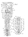
- Figure 1 is a sectional view of part of an injector in accordance with an embodiment;
- Figure 2 is a view, to an enlarged scale, of part of the injector of Figure 1;
- Figures 3 and 4 are views similar to Figures 1 and 2 illustrating an alternative embodiment; and
- Figure 5 is a view similar to Figure 2 illustrating a further embodiment.
-
- The fuel injector illustrated in Figures 1 and 2 comprises a
nozzle body 10 provided with ablind bore 12. Adjacent the blind end of the bore, thebore 12 is shaped to define a seating of substantially frusto-conical shape. Anouter valve needle 14 is slidable within thebore 12, theouter valve needle 14 defining, adjacent its lower end, a region of substantially frusto-conical shape arranged to engage the frusto-conical seating to control the supply of fuel from thebore 12 to a first group ofoutlet openings 16. - The upper end of the
outer valve needle 14 is shaped to be of diameter substantially equal to the diameter of the adjacent parts of thebore 12 to form a substantially fluid tight seal therewith and to guide theouter valve needle 14 for sliding movement in thebore 12. As illustrated in Figure 1, theouter valve needle 14 further includes a lower region of smaller diameter, the relatively large diameter upper region and the lower, small diameter region together defining anangled thrust surface 18 which is exposed to the fuel pressure within achamber 20 defined between the lower part of theouter valve needle 14 and the adjacent part of thebore 12. A part of the lower, conical end surface of theouter valve needle 14 is also exposed to the fuel pressure within thechamber 20. - The
bore 12 defines anannular gallery 22 in communication with asupply passage 24 which, in use, communicates with a source of fuel under pressure, for example a common rail charged with fuel by an appropriate fuel pump. - The
outer valve needle 14 is provided withflutes 26 whereby fuel is able to flow from theannular gallery 22 to thechamber 20. - The
outer valve needle 14 is provided with an axially extendingbore 28, aninner valve needle 30 being slidable within the lower part of thebore 28. Theinner valve needle 30 is shaped, at its lower end, to define a frusto-conical region which is engageable with a part of a seating located closer to the lower end of thenozzle body 10 than the first group ofopenings 16. A second group ofopenings 32 communicate with thebore 12 downstream of the position at which theinner valve needle 30 engages the seating. It will be appreciated that the engagement between theinner valve needle 30 and the seating controls the supply of fuel under pressure to the second group ofoutlet openings 32. - As shown most clearly in Figure 2, the upper end surface of the
inner valve needle 30 is provided with arecess 34, the provision of therecess 34 resulting in the upper part of theinner valve needle 30 being of relatively small wall thickness. Therecess 34 is conveniently formed using a low force machining technique, for example electric discharge or electrochemical machining. Aload transmitting member 36 engages in therecess 34, the upper end of themember 36 engaging ashim 38, which in turn engages ahelical compression spring 40. Theload transmitting member 36 is shaped to be engageable with a step or shoulder defined by part of thebore 28 to limit movement of theinner valve needle 30 relative to theouter valve needle 14. - At its upper end, the
nozzle body 10 engages adistance piece 42, thedistance piece 42 being provided with afirst drilling 44 whereby fuel under pressure from the fuel source is supplied to thesupply passage 24. A flow restrictor is provided in thedrilling 44. - The
distance piece 42 is further provided with a recess of annular shape defining acontrol chamber 46, the upper part of theouter valve needle 14 being exposed to the fuel pressure within thecontrol chamber 46. Aspring 48 is located within thecontrol chamber 46, thespring 48 engaging the upper surface of theouter valve needle 14 to bias thevalve needle 14 into engagement with the seating. Asmall diameter drilling 50 provides a restricted flow path between thefirst drilling 44 and thecontrol chamber 46. It will be appreciated that, in use, the provision of the restrictor in thedrilling 44 permits the formation of a pressure differential across thevalve needles - Within the
control chamber 46, thedistance piece 42 defines aprojection 52 provided with an axially extending passage 54. Thespring 40 engages the lower end of theprojection 52. The passage 54 communicates through a restrictedpassage 56 with arecess 58 formed in the upper surface of thedistance piece 42, a further restrictedpassage 60 connecting therecess 58 to thefirst drilling 44. - The upper end of the
distance piece 42 engages avalve housing 62 provided with asecond drilling 64 communicating with thefirst drilling 44. Thevalve housing 62 is further provided with athrough bore 66 within which avalve member 68 is slidable, thevalve member 68 including a region engageable with a seating to control communication between a passage 70 which communicates with therecess 58, and achamber 72 which communicates, in use, with a low pressure drain reservoir. Thevalve member 68 is spring biased into engagement with its seating, and movement of thevalve member 68 away from its seating is controlled by an electromagnetic actuator (not shown) which, in conjunction with anarmature 74 carried by thevalve member 68 can apply a force to thevalve member 68 to lift thevalve member 68 from its seating. - In use, with the
supply passage 24 communicating with the source of fuel under high pressure, and with the actuator de-energized so that thevalve member 68 engages its seating, the fuel pressure within thechamber 20 is relatively high, thus a force is applied to thevalve needle 14 urging thevalve needle 14 away from the seating. This force is countered by the action of the fuel under pressure within thecontrol chamber 46 and the action of thespring 48 with the result that the lower end of theouter valve needle 14 engages the seating. As a result, it will be appreciated that fuel under pressure is unable to flow from thechamber 20 to a position downstream of the engagement of theouter valve needle 14 with the seating. Fuel is therefore unable to flow to either of the first or second groups ofoutlet openings - At this point in the operating cycle of the injector, it will be appreciated that the fuel pressure within the
bore 28 of theouter valve needle 14 is high, thus the upper end of theinner valve needle 30 is exposed to fuel under high pressure. The action of the fuel under pressure upon the upper end surface of theinner valve needle 30 in combination with the action of thespring 40 maintains theinner valve needle 30 in engagement with the seating. The action of the fuel under pressure on the upper part of theinner valve needle 30, and in particular the action of the fuel under high pressure within therecess 34 acts to deform the upper part of theinner valve needle 30 to expand the outer diameter thereof, thus forming a substantially fluid tight seal between the inner andouter valve needles - In order to commence injection, the actuator is energized, and as a result the
valve member 68 is lifted from its seating. Fuel is able to escape from thecontrol chamber 46 through thepassages 54, 56, therecess 58 and the passage 70 to the low pressure reservoir. The fuel pressure within thecontrol chamber 46 applied to the upper surface of theouter valve needle 14 is therefore reduced, and a point will be reached beyond which the force urging thevalve needle 14 away from its seating is sufficient to overcome the action of thespring 48 and the fuel pressure within thecontrol chamber 46, and theouter valve needle 14 will lift away from the seating, thus permitting fuel to flow to the first group ofoutlet openings 16. The flow of fuel across the open end of thebore 28 maintains the fuel pressure within thebore 28 to which the upper end surface of theinner valve needle 30 is exposed at a relatively high pressure, thus although theouter valve needle 14 moves, theinner valve needle 30 remains in contact with the seating. As a result, it will be appreciated that fuel delivery occurs only through the first group ofoutlet openings 16, fuel not being delivered through the second group ofoutlet openings 32 at this time. Additionally, as the inner valve needle does not move, it can assist in guiding the movement of the outer needle. - Once the
outer valve needle 14 has lifted to its fully opened position, the upper end thereof engages theprojection 52, thus the flow of fuel from thecontrol chamber 46 to the low pressure drain through the passage 54 is terminated. Fuel flows to thecontrol chamber 46 through the restrictedpassage 50, thus the fuel pressure within thecontrol chamber 46 rises. However, as, at this point in the injection cycle, the effective area over which fuel under pressure acts to urge the needle away from the seating is large, the increase in fuel pressure within thecontrol chamber 46 does not result in movement of theneedle 14 to terminate injection. As the flow of fuel from thecontrol chamber 46 to the low pressure drain is terminated, the fuel pressure within thebore 28 starts to fall, reducing the deformation of theinner valve needle 30. Further, a point will be reached beyond which the fuel pressure acting upon the exposed part of theinner valve needle 30 is able to lift theinner valve needle 30 against the action of thespring 40 in combination with the remaining fuel pressure within thebore 28 to allow fuel injection through both the first group ofoutlet openings 16 and the second group ofoutlet openings 32. Movement of theinner valve needle 30 is limited by engagement between themember 36 and the step defined by thebore 28. - In order to terminate injection, the actuator is de-energized, and the flow of fuel to the low pressure drain terminates. Fuel is able to flow to the
bore 28 through thepassages inner valve needle 30. When the fuel pressure above theinner needle 30 exceeds that beneath theneedle 30, movement of theinner valve needle 30 into engagement with the seating takes place, and the upper part of theneedle 30 is deformed to form a seal with theouter valve needle 14. The fuel under pressure within thebore 28 further increases the downward force applied to theouter valve needle 14 to an extent sufficient to cause movement of theneedle 14 into engagement with the seating to terminate injection through the first group ofoutlet openings 16. - It will be appreciated that the embodiment of Figures 1 and 2 has the advantages that a single actuator is used to control movement of both the
outer valve needle 14 and theinner valve needle 30. Further, the escape of fuel between the inner and outer valve needles 14, 30 is reduced or avoided. - In the arrangement described hereinbefore, movement of the inner valve needle occurs only when the pressure of fuel applied to the injector exceeds a predetermined level and when the outer needle has reached its fully lifted position. By appropriate control of the injector, the total area of the outlet openings in use can be controlled to permit the duration of injection to be maintained at a relatively low level even under high engine speed or load conditions.
- Figures 3 and 4 illustrate an arrangement which is similar to that of Figures 1 and 2, but in which the fuel pressure within the
control chamber 46 is controlled using a piezoelectric actuator arrangement which controls the position of apiston 76. The inner and outer valve needles 14, 30 are both exposed, throughout the range of movement of theouter valve needle 14, to the fuel pressure within thecontrol chamber 46, thus movement of both of the valve needles is dependent upon the pressure differential between the upper and lower surfaces thereof, the effective cross sectional areas exposed to the fuel under pressure and the effect of spring biasing. In the arrangement illustrated in Figures 3 and 4, theinner valve needle 30 is not spring biased, the only spring biasing being by way of aspring 78 which is engaged between thepiston 76 and ashim 80 which engages a shoulder defined by thebore 28. Thespring 78 serves to maintain theouter valve needle 14 in engagement with the seating when fuel under pressure is not being supplied to the injector. - In use, initially the
piston 76 is urged by the piezoelectric actuator towards a position in which the fuel pressure within thecontrol chamber 46 is maintained at a high level. The application of high pressure to thecontrol chamber 46 maintains the inner and outer valve needles 14, 30 in engagement with the seating against the action of fuel under pressure within thechamber 20. In order to commence injection, the piezoelectric actuator is energized to permit movement of thepiston 76 to reduce the fuel pressure within thecontrol chamber 46, and as a result theouter valve needle 14 moves to permit fuel delivery through the first group ofoutlet openings 16. This movement occurs against the action of thespring 78, and results from the pressure differential between the upper and lower surfaces of thevalve needle 14 and the effective areas to which fuel under pressure is applied. - Once the
outer valve needle 14 has lifted, fuel under pressure is applied to theinner valve needle 30. If thepiston 76 is moved to reduce the pressure within thecontrol chamber 46 relative to that applied to the lower part of theneedle 30, theinner valve needle 30 is able to move against the action of the fuel pressure within thecontrol chamber 46 to permit fuel delivery through both the first group ofoutlet openings 16 and the second group ofoutlet openings 32. - Termination of injection occurs by energizing the piezoelectric actuator to move the
piston 76 to increase the fuel pressure within thecontrol chamber 46. As a result, the fuel pressure applied to the inner and outer valve needles 14, 30 increases, and a point will be reached beyond which the fuel pressure within thecontrol chamber 46 is sufficient to cause the valve needles 14, 30 to return into engagement with their respective seatings. - As described hereinbefore, the embodiment of Figures 3 and 4 requires the provision of only a single actuator to control movement of the inner and outer valve needles 14, 30, and leakage of fuel between the inner and outer valve needles 14, 30 is restricted by the application of fuel under pressure to the
recess 34 provided in the upper part of theinner valve needle 30 deforming theinner valve needle 30 to form a substantially fluid tight seal with theouter valve needle 14. - Figure 5 illustrates an arrangement in which an
inner needle 30 is slidable within ablind bore 28 formed in theouter needle 14. Theinner needle 30 and bore 28 together define achamber 92 which communicates, through a restrictedpassage 94 with a part of thebore 12 upstream of the first group ofoutlet openings 16. - In use, an appropriate actuator is used to control movement of the
outer needle 14. If theouter needle 14 moves slowly, the fuel is able to flow at a sufficiently high rate through thepassage 94 to thechamber 92 to ensure that theinner needle 30 remains seated. However, if theouter needle 14 moves quickly, the fuel pressure within thechamber 92 will fall as fuel is unable to flow to thechamber 92 at a sufficient rate to maintain the fuel pressure within the chamber, and theinner needle 30 will lift away from its seating. During injection, as fuel can continue to flow, at a low rate, to thechamber 92, theinner needle 30 will gradually move towards its seating. - As described hereinbefore, the
inner needle 30 is provided with arecess 34 such that the application of fuel under pressure to thechamber 92 causes dilation of theinner needle 30 to improve the seal between theinner needle 30 and thebore 28, thus reducing fuel leakage.
Claims (3)
- A fuel injector comprising an outer valve needle (14) and an inner valve needle (30), the inner valve needle (30) being slidable within a bore (28) formed in the outer valve needle (14), the inner and outer valve needles (14, 30) being exposed to fuel pressure within a control chamber (46), and a single actuator being arranged to control the fuel pressure within the control chamber (46).
- A fuel injector as claimed in Claim 1, wherein the actuator arrangement comprises an electromagnetically actuable valve (68).
- A fuel injector as claimed in Claim 1, wherein the actuator arrangement comprises a piston (76) arranged to be moved by a piezoelectric actuator.
Applications Claiming Priority (3)
| Application Number | Priority Date | Filing Date | Title |
|---|---|---|---|
| GBGB9813476.0A GB9813476D0 (en) | 1998-06-24 | 1998-06-24 | Fuel injector |
| GB9813476 | 1998-06-24 | ||
| EP99304086A EP0967383B1 (en) | 1998-06-24 | 1999-05-26 | Fuel injector |
Related Parent Applications (1)
| Application Number | Title | Priority Date | Filing Date |
|---|---|---|---|
| EP99304086A Division EP0967383B1 (en) | 1998-06-24 | 1999-05-26 | Fuel injector |
Publications (2)
| Publication Number | Publication Date |
|---|---|
| EP1382836A1 true EP1382836A1 (en) | 2004-01-21 |
| EP1382836B1 EP1382836B1 (en) | 2008-03-05 |
Family
ID=10834200
Family Applications (2)
| Application Number | Title | Priority Date | Filing Date |
|---|---|---|---|
| EP99304086A Expired - Lifetime EP0967383B1 (en) | 1998-06-24 | 1999-05-26 | Fuel injector |
| EP03078016A Expired - Lifetime EP1382836B1 (en) | 1998-06-24 | 1999-05-26 | Fuel injector |
Family Applications Before (1)
| Application Number | Title | Priority Date | Filing Date |
|---|---|---|---|
| EP99304086A Expired - Lifetime EP0967383B1 (en) | 1998-06-24 | 1999-05-26 | Fuel injector |
Country Status (4)
| Country | Link |
|---|---|
| US (1) | US6220528B1 (en) |
| EP (2) | EP0967383B1 (en) |
| DE (2) | DE69918902T2 (en) |
| GB (1) | GB9813476D0 (en) |
Families Citing this family (36)
| Publication number | Priority date | Publication date | Assignee | Title |
|---|---|---|---|---|
| DE69922087T2 (en) * | 1998-06-24 | 2005-12-01 | Delphi Technologies, Inc., Troy | fuel injector |
| GB9913314D0 (en) * | 1999-06-09 | 1999-08-11 | Lucas Ind Plc | Fuel injector |
| DE10004971A1 (en) * | 2000-02-04 | 2001-08-09 | Bosch Gmbh Robert | Automotive fuel injection valve fits baffle on valve needle downstream of fuel channel below magnet armature as forced down by fuel impacting baffle. |
| DE10032924A1 (en) * | 2000-07-06 | 2002-01-24 | Bosch Gmbh Robert | Fuel injection device for internal combustion engines |
| DE10034444A1 (en) * | 2000-07-15 | 2002-01-24 | Bosch Gmbh Robert | Fuel injector |
| US6557779B2 (en) * | 2001-03-02 | 2003-05-06 | Cummins Engine Company, Inc. | Variable spray hole fuel injector with dual actuators |
| DE10118163B4 (en) * | 2001-04-11 | 2007-04-19 | Robert Bosch Gmbh | Fuel injector |
| US6601566B2 (en) * | 2001-07-11 | 2003-08-05 | Caterpillar Inc | Fuel injector with directly controlled dual concentric check and engine using same |
| US6637675B2 (en) * | 2001-07-13 | 2003-10-28 | Cummins Inc. | Rate shaping fuel injector with limited throttling |
| US6557776B2 (en) * | 2001-07-19 | 2003-05-06 | Cummins Inc. | Fuel injector with injection rate control |
| DE10141678A1 (en) * | 2001-08-25 | 2003-05-08 | Bosch Gmbh Robert | Fuel injection device for an internal combustion engine |
| DE10149277A1 (en) * | 2001-10-05 | 2003-04-24 | Siemens Ag | Fuel injection valve, for an IC motor, has grooves at the conical tip of the valve needle matching the injection openings in the valve body |
| US6725838B2 (en) | 2001-10-09 | 2004-04-27 | Caterpillar Inc | Fuel injector having dual mode capabilities and engine using same |
| DE10152253B4 (en) * | 2001-10-20 | 2014-10-09 | Robert Bosch Gmbh | Valve for controlling fluids |
| DE10221384A1 (en) * | 2002-05-14 | 2003-11-27 | Bosch Gmbh Robert | Fuel injection device for an internal combustion engine |
| DE10222196A1 (en) * | 2002-05-18 | 2003-11-27 | Bosch Gmbh Robert | Fuel injection valve for combustion engine, has control valve with valve chamber and valve member that is moveable between two end positions for opening or closing connections to certain chambers |
| US6978760B2 (en) * | 2002-09-25 | 2005-12-27 | Caterpillar Inc | Mixed mode fuel injector and injection system |
| US6769635B2 (en) | 2002-09-25 | 2004-08-03 | Caterpillar Inc | Mixed mode fuel injector with individually moveable needle valve members |
| DE10247958A1 (en) * | 2002-10-15 | 2004-04-29 | Robert Bosch Gmbh | Fuel injection device for an internal combustion engine |
| DE10248379A1 (en) * | 2002-10-17 | 2004-04-29 | Robert Bosch Gmbh | Fuel injection device for an internal combustion engine |
| US6945475B2 (en) | 2002-12-05 | 2005-09-20 | Caterpillar Inc | Dual mode fuel injection system and fuel injector for same |
| DE10304605A1 (en) * | 2003-02-05 | 2004-08-19 | Robert Bosch Gmbh | Fuel injector with two coaxial valve needles |
| DE10312586A1 (en) * | 2003-03-21 | 2004-09-30 | Robert Bosch Gmbh | Fuel injection valve for internal combustion engines |
| DE10326044A1 (en) * | 2003-06-10 | 2004-12-30 | Robert Bosch Gmbh | Injection nozzle for internal combustion engines |
| DE10326045A1 (en) * | 2003-06-10 | 2004-12-30 | Robert Bosch Gmbh | Injection nozzle for internal combustion engines |
| DE10343998A1 (en) * | 2003-09-23 | 2005-04-14 | Robert Bosch Gmbh | injection |
| DE602005001261T2 (en) | 2005-01-19 | 2008-01-31 | Delphi Technologies, Inc., Troy | Fuel injector |
| DE602005005159T2 (en) * | 2005-01-19 | 2009-04-30 | Delphi Technologies, Inc., Troy | Fuel injection valve |
| US7597084B2 (en) * | 2005-03-09 | 2009-10-06 | Caterpillar Inc. | Internal combustion engine and operating method therefor |
| US8069835B2 (en) * | 2005-03-09 | 2011-12-06 | Caterpillar Inc. | Internal combustion engine and operating method therefor |
| JP4772016B2 (en) * | 2007-09-07 | 2011-09-14 | トヨタ自動車株式会社 | Fuel injection control device for internal combustion engine |
| EP2071178A1 (en) * | 2007-12-10 | 2009-06-17 | Delphi Technologies, Inc. | Injection nozzle |
| US7980224B2 (en) * | 2008-02-05 | 2011-07-19 | Caterpillar Inc. | Two wire intensified common rail fuel system |
| CN105636705B (en) * | 2013-09-16 | 2018-06-19 | 泰华施公司 | For the nozzle of distribution system |
| NL1041770B1 (en) * | 2016-03-18 | 2017-10-03 | Cereus Tech B V | Improved fuel injection devices. |
| US11105307B2 (en) | 2017-02-03 | 2021-08-31 | Transportation Ip Holdings, Llc | Method and systems for a multi-needle fuel injector |
Citations (4)
| Publication number | Priority date | Publication date | Assignee | Title |
|---|---|---|---|---|
| DE3824467A1 (en) * | 1988-07-19 | 1990-01-25 | Man B & W Diesel Ag | Injection valve |
| DE4115477A1 (en) * | 1990-05-17 | 1991-11-21 | Avl Verbrennungskraft Messtech | Injection nozzle for IC engine - has hollow needle controlling first group of injection holes and loaded by first spring towards its closure position |
| EP0816670A1 (en) * | 1996-07-02 | 1998-01-07 | Siemens Automotive Corporation | Piezoelectric controlled common rail injector with hydraulic amplification of piezoelectric stroke |
| EP0878623A2 (en) * | 1997-05-14 | 1998-11-18 | Lucas Industries Public Limited Company | Fuel injector |
Family Cites Families (7)
| Publication number | Priority date | Publication date | Assignee | Title |
|---|---|---|---|---|
| DE2342109C2 (en) * | 1973-08-21 | 1983-10-27 | Robert Bosch Gmbh, 7000 Stuttgart | Electromechanically controlled fuel injection valve for internal combustion engines |
| DE2710138A1 (en) * | 1977-03-09 | 1978-09-14 | Maschf Augsburg Nuernberg Ag | MULTI-HOLE INJECTION NOZZLE |
| DE2710216A1 (en) * | 1977-03-09 | 1978-09-14 | Bosch Gmbh Robert | FUEL INJECTOR |
| DE3236046C2 (en) * | 1982-09-29 | 1986-03-20 | Daimler-Benz Ag, 7000 Stuttgart | Fuel injector for internal combustion engines |
| JPS6036772A (en) * | 1983-08-10 | 1985-02-25 | Diesel Kiki Co Ltd | Fuel injection valve |
| US4826081A (en) * | 1987-08-20 | 1989-05-02 | Zwick Eugene B | Unit type fuel injector for low lubricity, low viscosity fuels |
| US5458292A (en) * | 1994-05-16 | 1995-10-17 | General Electric Company | Two-stage fuel injection nozzle |
-
1998
- 1998-06-24 GB GBGB9813476.0A patent/GB9813476D0/en not_active Ceased
-
1999
- 1999-05-26 EP EP99304086A patent/EP0967383B1/en not_active Expired - Lifetime
- 1999-05-26 DE DE69918902T patent/DE69918902T2/en not_active Expired - Lifetime
- 1999-05-26 DE DE69938314T patent/DE69938314T2/en not_active Expired - Lifetime
- 1999-05-26 EP EP03078016A patent/EP1382836B1/en not_active Expired - Lifetime
- 1999-06-02 US US09/324,621 patent/US6220528B1/en not_active Expired - Lifetime
Patent Citations (4)
| Publication number | Priority date | Publication date | Assignee | Title |
|---|---|---|---|---|
| DE3824467A1 (en) * | 1988-07-19 | 1990-01-25 | Man B & W Diesel Ag | Injection valve |
| DE4115477A1 (en) * | 1990-05-17 | 1991-11-21 | Avl Verbrennungskraft Messtech | Injection nozzle for IC engine - has hollow needle controlling first group of injection holes and loaded by first spring towards its closure position |
| EP0816670A1 (en) * | 1996-07-02 | 1998-01-07 | Siemens Automotive Corporation | Piezoelectric controlled common rail injector with hydraulic amplification of piezoelectric stroke |
| EP0878623A2 (en) * | 1997-05-14 | 1998-11-18 | Lucas Industries Public Limited Company | Fuel injector |
Also Published As
| Publication number | Publication date |
|---|---|
| DE69918902D1 (en) | 2004-09-02 |
| DE69938314T2 (en) | 2009-02-26 |
| DE69938314D1 (en) | 2008-04-17 |
| EP1382836B1 (en) | 2008-03-05 |
| US6220528B1 (en) | 2001-04-24 |
| EP0967383B1 (en) | 2004-07-28 |
| EP0967383A2 (en) | 1999-12-29 |
| GB9813476D0 (en) | 1998-08-19 |
| EP0967383A3 (en) | 2000-12-06 |
| DE69918902T2 (en) | 2005-07-28 |
Similar Documents
| Publication | Publication Date | Title |
|---|---|---|
| EP0967383B1 (en) | Fuel injector | |
| US6776354B2 (en) | Fuel injector | |
| US5605134A (en) | High pressure electronic common rail fuel injector and method of controlling a fuel injection event | |
| US6267306B1 (en) | Fuel injector including valve needle, injection control valve, and drain valve | |
| EP2050951B1 (en) | Fuel injector | |
| EP1063417A1 (en) | Fuel injector | |
| WO2001075296A1 (en) | Closed nozzle fuel injector with improved controllability | |
| EP1163440B1 (en) | Fuel injector | |
| EP1717440A1 (en) | Fluid injection nozzle | |
| EP0943797A1 (en) | Fuel injector | |
| US7568634B2 (en) | Injection nozzle | |
| EP1136692B1 (en) | Fuel injector with a control rod controlled by the fuel pressure in a control chamber | |
| EP0844383B1 (en) | Injector | |
| US6340017B1 (en) | Fuel injector | |
| US6209805B1 (en) | Fuel injector | |
| WO2000017506A1 (en) | Servo-controlled fuel injector with leakage limiting device | |
| EP0987432B1 (en) | Fuel injector | |
| GB2336628A (en) | A fuel injector, for an I.C. engine, having a three way two position needle control valve | |
| US6321999B1 (en) | Fuel injector | |
| EP1065368A2 (en) | Fuel injector | |
| EP1236883A2 (en) | Fuel system | |
| EP1143139A1 (en) | Fuel system | |
| EP1063422B1 (en) | Fuel injector | |
| EP1079096A2 (en) | Fuel injector arrangement | |
| JP2632713B2 (en) | Fuel injection device |
Legal Events
| Date | Code | Title | Description |
|---|---|---|---|
| PUAI | Public reference made under article 153(3) epc to a published international application that has entered the european phase |
Free format text: ORIGINAL CODE: 0009012 |
|
| 17P | Request for examination filed |
Effective date: 20031023 |
|
| AC | Divisional application: reference to earlier application |
Ref document number: 0967383 Country of ref document: EP Kind code of ref document: P |
|
| AK | Designated contracting states |
Kind code of ref document: A1 Designated state(s): DE ES FR GB IT |
|
| AKX | Designation fees paid |
Designated state(s): DE ES FR GB IT |
|
| GRAP | Despatch of communication of intention to grant a patent |
Free format text: ORIGINAL CODE: EPIDOSNIGR1 |
|
| GRAS | Grant fee paid |
Free format text: ORIGINAL CODE: EPIDOSNIGR3 |
|
| GRAA | (expected) grant |
Free format text: ORIGINAL CODE: 0009210 |
|
| AC | Divisional application: reference to earlier application |
Ref document number: 0967383 Country of ref document: EP Kind code of ref document: P |
|
| AK | Designated contracting states |
Kind code of ref document: B1 Designated state(s): DE ES FR GB IT |
|
| REG | Reference to a national code |
Ref country code: GB Ref legal event code: FG4D |
|
| REF | Corresponds to: |
Ref document number: 69938314 Country of ref document: DE Date of ref document: 20080417 Kind code of ref document: P |
|
| PG25 | Lapsed in a contracting state [announced via postgrant information from national office to epo] |
Ref country code: ES Free format text: LAPSE BECAUSE OF FAILURE TO SUBMIT A TRANSLATION OF THE DESCRIPTION OR TO PAY THE FEE WITHIN THE PRESCRIBED TIME-LIMIT Effective date: 20080616 |
|
| ET | Fr: translation filed | ||
| PLBE | No opposition filed within time limit |
Free format text: ORIGINAL CODE: 0009261 |
|
| STAA | Information on the status of an ep patent application or granted ep patent |
Free format text: STATUS: NO OPPOSITION FILED WITHIN TIME LIMIT |
|
| 26N | No opposition filed |
Effective date: 20081208 |
|
| GBPC | Gb: european patent ceased through non-payment of renewal fee |
Effective date: 20080605 |
|
| PG25 | Lapsed in a contracting state [announced via postgrant information from national office to epo] |
Ref country code: GB Free format text: LAPSE BECAUSE OF NON-PAYMENT OF DUE FEES Effective date: 20080605 |
|
| PGFP | Annual fee paid to national office [announced via postgrant information from national office to epo] |
Ref country code: IT Payment date: 20090520 Year of fee payment: 11 Ref country code: FR Payment date: 20090515 Year of fee payment: 11 |
|
| REG | Reference to a national code |
Ref country code: FR Ref legal event code: ST Effective date: 20110131 |
|
| PG25 | Lapsed in a contracting state [announced via postgrant information from national office to epo] |
Ref country code: IT Free format text: LAPSE BECAUSE OF NON-PAYMENT OF DUE FEES Effective date: 20100526 |
|
| PG25 | Lapsed in a contracting state [announced via postgrant information from national office to epo] |
Ref country code: FR Free format text: LAPSE BECAUSE OF NON-PAYMENT OF DUE FEES Effective date: 20100531 |
|
| PGFP | Annual fee paid to national office [announced via postgrant information from national office to epo] |
Ref country code: DE Payment date: 20120529 Year of fee payment: 14 |
|
| PG25 | Lapsed in a contracting state [announced via postgrant information from national office to epo] |
Ref country code: DE Free format text: LAPSE BECAUSE OF NON-PAYMENT OF DUE FEES Effective date: 20131203 |
|
| REG | Reference to a national code |
Ref country code: DE Ref legal event code: R119 Ref document number: 69938314 Country of ref document: DE Effective date: 20131203 |