EP1382834A1 - An induction unit for a motorcycle - Google Patents
An induction unit for a motorcycle Download PDFInfo
- Publication number
- EP1382834A1 EP1382834A1 EP02425466A EP02425466A EP1382834A1 EP 1382834 A1 EP1382834 A1 EP 1382834A1 EP 02425466 A EP02425466 A EP 02425466A EP 02425466 A EP02425466 A EP 02425466A EP 1382834 A1 EP1382834 A1 EP 1382834A1
- Authority
- EP
- European Patent Office
- Prior art keywords
- motorcycle
- induction
- induction unit
- box
- induction box
- Prior art date
- Legal status (The legal status is an assumption and is not a legal conclusion. Google has not performed a legal analysis and makes no representation as to the accuracy of the status listed.)
- Withdrawn
Links
Images


Classifications
-
- F—MECHANICAL ENGINEERING; LIGHTING; HEATING; WEAPONS; BLASTING
- F02—COMBUSTION ENGINES; HOT-GAS OR COMBUSTION-PRODUCT ENGINE PLANTS
- F02M—SUPPLYING COMBUSTION ENGINES IN GENERAL WITH COMBUSTIBLE MIXTURES OR CONSTITUENTS THEREOF
- F02M35/00—Combustion-air cleaners, air intakes, intake silencers, or induction systems specially adapted for, or arranged on, internal-combustion engines
- F02M35/16—Combustion-air cleaners, air intakes, intake silencers, or induction systems specially adapted for, or arranged on, internal-combustion engines characterised by use in vehicles
- F02M35/162—Motorcycles; All-terrain vehicles, e.g. quads, snowmobiles; Small vehicles, e.g. forklifts
-
- F—MECHANICAL ENGINEERING; LIGHTING; HEATING; WEAPONS; BLASTING
- F02—COMBUSTION ENGINES; HOT-GAS OR COMBUSTION-PRODUCT ENGINE PLANTS
- F02B—INTERNAL-COMBUSTION PISTON ENGINES; COMBUSTION ENGINES IN GENERAL
- F02B61/00—Adaptations of engines for driving vehicles or for driving propellers; Combinations of engines with gearing
- F02B61/02—Adaptations of engines for driving vehicles or for driving propellers; Combinations of engines with gearing for driving cycles
-
- F—MECHANICAL ENGINEERING; LIGHTING; HEATING; WEAPONS; BLASTING
- F02—COMBUSTION ENGINES; HOT-GAS OR COMBUSTION-PRODUCT ENGINE PLANTS
- F02M—SUPPLYING COMBUSTION ENGINES IN GENERAL WITH COMBUSTIBLE MIXTURES OR CONSTITUENTS THEREOF
- F02M25/00—Engine-pertinent apparatus for adding non-fuel substances or small quantities of secondary fuel to combustion-air, main fuel or fuel-air mixture
- F02M25/08—Engine-pertinent apparatus for adding non-fuel substances or small quantities of secondary fuel to combustion-air, main fuel or fuel-air mixture adding fuel vapours drawn from engine fuel reservoir
Definitions
- the present invention relates to an induction unit for a motorcycle.
- the induction unit according to the present invention is positioned under the fuel tank and comprises an air intake duct and a large induction box through which the air enters the motorcycle engine.
- Induction units of this type are known, for example, from patent publication EP-1 083 330.
- This document describes an air cleaner located in the space under the motorcycle fuel tank and made in such a way as not to alter the mounting height of the fuel tank itself and so as to provide the engine with a large induction box.
- Japanese patent application JP-11-192989 discloses an intake duct which carries air to a filter box and which is designed to be easily fixable and adaptable to the internal and external structure of the motorcycle.
- the present invention therefore has for an object to provide a motorcycle engine induction unit which accommodates within its mounting space other accessories or components of the motorcycle and which can be easily preassembled and fitted within the motorcycle structure.
- the present invention discloses an induction unit for a motorcycle as described in the independent claim below.
- the numeral 1 denotes an induction unit for a motorcycle.
- the motorcycle induction unit 1 comprises at least one intake duct 2, 3, an induction box 4 connected to the intake duct 2, 3 and at least one container 5, 6 for auxiliary systems 7,8.
- the left container 5 houses a device (or canister) for the recovery of fuel vapours from a fuel tank 8, and the container 6 is a coolant expansion tank connected to a radiator 7.
- the induction unit 1 comprises two intake ducts 2, 3, which are connected to the induction box 4 through appropriate fixing means 9, for example a set of screws 10, and which come from the front 11 of the motorcycle.
- the ducts 2, 3 are slotted in appropriate seats 11a made in the front 11 which in practice consists of a fairing 12.
- Each duct 2, 3 has one end 13 connected to the induction box 4 and a second end 14 connected to the fairing 12.
- each duct 2, 3 has an air cleaning element 15 which may be pre-assembled and which is mounted between each duct 2, 3 and the induction box 4.
- the air cleaning element 15 is substantially in the shape of an oblique prism with a triangular base and rounded edges. This shape constitutes an optimum compromise between the need to limit the space occupied by the cleaning element 15 in the induction box 4 and the need to provide the largest possible filtering surface.
- Suitable openings 16, 17 are made in the induction box 4 to accommodate the air cleaning element 15. These openings 16, 17 are slightly larger in size than the air cleaning element 15 so that the latter can be easily inserted into and removed from the induction box 4.
- the air cleaning element 15 has a sealed edge 15a that fits between the induction box 4 and the respective intake duct 2, 3.
- Changing the air cleaning element 15 is therefore very easy not only because the induction box 4 need not be opened but also because the openings 16, 17 are located on the sides and it is not therefore necessary to remove the parts above the induction box 4, for example, the fuel tank 8.
- the induction box 4 comprises a base 18 and a lid 19, on which a part of the fuel mixing means 20 may be mounted.
- the fuel mixing means 20 may comprise injectors 21, air chokes 22 and throttle bodies 22a or carburettors (not illustrated).
- Figure 4 shows an air choke 22 and the related injector 21 fitted to it.
- the injectors 21 are mounted on the lid 19 through holes 23 made in the lid 19 itself, while the throttle bodies 22a are mounted on the base 18 through holes 24 made in the base 18 itself.
- the throttle bodies 22a also serve as a support for the entire induction box 4 and since the throttle bodies 22a (or the carburettors) are in turn supported by the induction manifolds of the motorcycle engine, it follows that the induction box 4 is also supported by the engine.
- This arrangement is particularly convenient in engines with cylinders arranged in a Vee configuration where the induction manifolds are centrally positioned between the two cylinder banks.
- This configuration also facilitates connection between the motorcycle engine and the induction box 4 since the latter is not fixed to the motorcycle frame and is therefore not affected by the relative dimensional variations and tolerances between the frame fastenings, the induction box 4 itself and the engine induction manifolds.
- each injector 21 faces the inside of the induction box 4 at all times and is coaxial with the respective air choke 22 and throttle body 22a.
- the body of the injector 21 fits inside and seals the hole 23. This solution also improves the flow of air entering the engine because the absence of injector support elements means there is less load loss.
- the injectors 21 can be easily and directly accessed from the outside of the induction box 4 for substitution and maintenance without having to open the box 4 itself.
- the lid 19 is fixed to the base 18 by a plurality of fixing screws 19a.
- the outer edge 24 of the base 18 has a groove 26 made in it, where an elastomer seal 25 is fitted (see Fig. 1A).
- the seal 25 in the edge 24 is preferably made by a co-injection process. This process involves making the base 18 by injecting a hard plastic material into a mould matching the shape of the base 18 without the seal 25.
- the base 18 made in this way is then placed in the same mould after removing an element corresponding to the shape of the seal 25 from the mould, or the base 18 is placed in another mould that includes a cavity corresponding to the seal 25.
- the elastomeric material is injected into the mould to make the seal 25. This process effectively binds the seal 25 to the base 18 and achieves a perfect seal.
- the seal 25 cooperates with a rib 27 made on the lid 19 (Fig.1A) to achieve a perfect airtight seal.
- the positions of the seal 25 and of the rib 27 may be exchanged, that is to say, the seal may be located on the lid 19 and the rib 27 on the base 18.
- the lid 19 has a substantially flat, horizontal upper surface so as not to interfere with parts of the motorcycle that are above it, even when these parts are not aligned lengthways with the induction box 4, or when these parts can move lengthways, for example where the position of the tank 8 can be adjusted lengthways.
- An expansion chamber 28 located on one side of the induction box 4 and connected to the latter through a pipe 29 permits the expansion of the gases from the engine crankcase.
- the induction box 4 has holes 30, 31 made in it to enable maintenance to be performed on the components 21, 22, 22a located inside the induction box 4 without removing the lid 19.
- the holes 30, 31 are closed by appropriate plugs (not illustrated) made of an elastic material and having the shape of suction cups to provide an airtight seal.
- the vacuum inside the induction box 4 further improves the effect of the airtight seal by causing the suction cup parts of the plugs to adhere more closely.
- second openings 38 may be provided to house other accessories or systems, for example, to feed fuel to the mixing means 20, without unduly complicating the shape of the mould for the base 18.
- concertinaed covers (not illustrated) so as to hold the accessory or system within the induction box 4.
- the concertinaed covers may have passing through them the ducts for fluids (for example, fuel) and/or for electrical power lines and/or data transmission lines for the accessories and/or systems located inside the induction box 4.
- the intake ducts 2, 3 slot into the fairing 12 with their first ends 13 and into the induction box 4 with their second ends 14. Again, the ducts 2, 3 are not affected by dimensional variations and tolerances between the fastenings of the fairing and of the induction box 4 itself and are easy to adapt thanks to the seats 11a in the fairing 12.
- the ducts 2, 3 also comprise the containers 5, 6 moulded in a single piece.
- each duct 2, 3 consists of two half casings 32, 33, 34, 35, made in a single piece with the respective part of the containers 5, 6, which are also made in two halves.
- the half casings 32, 33, 34, 35 are then joined in pairs in such a way as to form the ducts 2, 3 and including the containers 5, 6.
- the half casings 32, 33, 34, 35 can be joined by gluing or welding and are preferably joined by ultrasound welding which uses ultrasound waves to generate vibrations capable of locally heating only the parts of the half casings 32, 33, 34, 35 to be joined.
- the containers 5, 6 comprise at least one fastening 36, 37 used to mount the auxiliary systems 7.
- the fastening 36, 37 is used to support and adjust the position of the radiator 7.
- the radiator 7 is therefore positioned and angled with reference to the fairing 12 and is independent of dimensional variations and tolerances of fastening points on the frame because, thanks to the fastenings 36, 37 of the containers 5, 6 connected to the ducts 2, 3, the entire unit is referenced to the fairing 12.
- the containers 5, 6 have an inside surface 51, 61 that is substantially flat and aligned with the lateral edges of the radiator 7, so as to channel the air flow towards the radiator 7.
- the invention achieves important advantages.
- the motorcycle engine induction unit according to the present invention is well integrated with the other parts of the motorcycle.
- it incorporates the coolant container and the canister.
- the induction unit according to the present invention can be easily fitted to the motorcycle because the induction box 4 is supported by the throttle bodies 22a (or the carburettors), which are in turn supported by the induction manifolds of the motorcycle engine, thus avoiding problems due to dimensional variations and tolerances of the components adjacent to the induction unit and of fastening points on the frame.
- the ducts 2, 3 - since they are supported by the fairing 12 and the induction box 4 - are also independent of dimensional variations and tolerances of the adjacent components.
- the ducts 2, 3 are in turn used as a reference for the radiator 7 which is thus exactly positioned and angled relative to the fairing 12.
- the motorcycle induction unit according to a preferred embodiment of the present invention enables the fuel injectors to be mounted directly on the lid 19 of the induction box 4.
- the special structure of the induction box 4 ensures quick and easy access to the fuel mixing means 20 and to the cleaning elements 15, thus facilitating maintenance and enabling the cleaning elements 15 to be conveniently changed without removing the lid 19 or the tank 8.
Landscapes
- Engineering & Computer Science (AREA)
- Chemical & Material Sciences (AREA)
- Combustion & Propulsion (AREA)
- Mechanical Engineering (AREA)
- General Engineering & Computer Science (AREA)
- Automatic Cycles, And Cycles In General (AREA)
Abstract
An induction unit (1) for a motorcycle comprises an
induction box (4) containing air cleaning elements
(15), and air intake ducts (2, 3), mounted between
the front (11) of the motorcycle and the induction
box (4) so as to channel air from the front (11) of
the motorcycle to the induction box (4). The air
intake ducts (2, 3) are connected with containers
(5, 6) for auxiliary systems (7, 8), for example,
the expansion container (6) for the coolant and the
canister (5). The air cleaning elements (15) are
preassembled on the air intake ducts (2, 3) so as
to facilitate assembly and dissassembly and are
prismatic in shape to optimise mounting space and
filtering surface area.
Description
- The present invention relates to an induction unit for a motorcycle. The induction unit according to the present invention is positioned under the fuel tank and comprises an air intake duct and a large induction box through which the air enters the motorcycle engine.
- Induction units of this type are known, for example, from patent publication EP-1 083 330. This document describes an air cleaner located in the space under the motorcycle fuel tank and made in such a way as not to alter the mounting height of the fuel tank itself and so as to provide the engine with a large induction box.
- Japanese patent application JP-11-192989 discloses an intake duct which carries air to a filter box and which is designed to be easily fixable and adaptable to the internal and external structure of the motorcycle.
- Current motorcycle manufacturers are extremely hard put to find space for the increasing number of additional components that have to be fitted to motorcycle engines to meet the latest pollution prevention legislation and the general changeover to engines with liquid cooling systems.
- In particular, to meet increasingly stringent anti-pollution regulations, engines are required to have fuel injection systems and fuel vapour recovery devices known in the jargon of the trade as canisters.
- For the engine cooling system, a coolant expansion chamber is now required.
- For these reasons, the available space inside the motorcycle is becoming smaller and smaller, whereas the induction system continues to require large volumes.
- Moreover, packing a larger number of components into the same amount of space also leads to interference between the induction unit and the other components of the motorcycle, such as the frame and the fuel tank, on account of the dimensional tolerances, that is, the dimensional variations between one component and another.
- The present invention therefore has for an object to provide a motorcycle engine induction unit which accommodates within its mounting space other accessories or components of the motorcycle and which can be easily preassembled and fitted within the motorcycle structure.
- In accordance with one aspect of it, the present invention discloses an induction unit for a motorcycle as described in the independent claim below.
- The dependent claims describe preferred, advantageous embodiments of the invention.
- The preferred embodiments of the invention will now be described, without restricting the scope of the inventive concept, with reference to the accompanying drawings in which:
- Figure 1 is a perspective view of the motorcycle induction unit according to the present invention, seen from the right;
- Figure 1A shows an enlarged detail of the motorcycle induction unit of Figure 1.
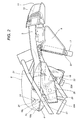
- Figure 2 is a right-hand side view of the motorcycle induction unit according of Figure 1;
- Figure 3 is a left-hand side view of the motorcycle induction unit illustrated in the figures listed above;
- Figure 4 is a top view of the motorcycle induction unit illustrated in the figures listed above.
- With reference to the accompanying drawings, the
numeral 1 denotes an induction unit for a motorcycle. - The
motorcycle induction unit 1 comprises at least oneintake duct induction box 4 connected to theintake duct container auxiliary systems - In the embodiment illustrated in the drawings, the
left container 5 houses a device (or canister) for the recovery of fuel vapours from afuel tank 8, and thecontainer 6 is a coolant expansion tank connected to aradiator 7. - It is emphasised that this is a preferred embodiment and that the containers may be used for purposes other than those mentioned above without departing from the scope of the inventive concept.
- The
induction unit 1 comprises twointake ducts induction box 4 through appropriate fixing means 9, for example a set ofscrews 10, and which come from thefront 11 of the motorcycle. In the embodiment illustrated in the drawings, theducts appropriate seats 11a made in thefront 11 which in practice consists of afairing 12. - Each
duct end 13 connected to theinduction box 4 and asecond end 14 connected to thefairing 12. - At its
first end 13, eachduct air cleaning element 15 which may be pre-assembled and which is mounted between eachduct induction box 4. - In the embodiment illustrated in the drawings, the
air cleaning element 15 is substantially in the shape of an oblique prism with a triangular base and rounded edges. This shape constitutes an optimum compromise between the need to limit the space occupied by thecleaning element 15 in theinduction box 4 and the need to provide the largest possible filtering surface. -
Suitable openings induction box 4 to accommodate theair cleaning element 15. Theseopenings air cleaning element 15 so that the latter can be easily inserted into and removed from theinduction box 4. Theair cleaning element 15 has a sealededge 15a that fits between theinduction box 4 and therespective intake duct - Changing the
air cleaning element 15 is therefore very easy not only because theinduction box 4 need not be opened but also because theopenings induction box 4, for example, thefuel tank 8. - The
induction box 4 comprises abase 18 and alid 19, on which a part of the fuel mixing means 20 may be mounted. - The fuel mixing means 20 may comprise
injectors 21,air chokes 22 andthrottle bodies 22a or carburettors (not illustrated). - For example, Figure 4 shows an
air choke 22 and therelated injector 21 fitted to it. - In another embodiment illustrated in Figures 2 and 3, the
injectors 21 are mounted on thelid 19 throughholes 23 made in thelid 19 itself, while thethrottle bodies 22a are mounted on thebase 18 throughholes 24 made in thebase 18 itself. - The
throttle bodies 22a (or the carburettors) also serve as a support for theentire induction box 4 and since thethrottle bodies 22a (or the carburettors) are in turn supported by the induction manifolds of the motorcycle engine, it follows that theinduction box 4 is also supported by the engine. - This arrangement is particularly convenient in engines with cylinders arranged in a Vee configuration where the induction manifolds are centrally positioned between the two cylinder banks.
- This configuration also facilitates connection between the motorcycle engine and the
induction box 4 since the latter is not fixed to the motorcycle frame and is therefore not affected by the relative dimensional variations and tolerances between the frame fastenings, theinduction box 4 itself and the engine induction manifolds. - The nozzle of each
injector 21 faces the inside of theinduction box 4 at all times and is coaxial with therespective air choke 22 andthrottle body 22a. - In the embodiment illustrated in Figures 2 and 3, the body of the
injector 21 fits inside and seals thehole 23. This solution also improves the flow of air entering the engine because the absence of injector support elements means there is less load loss. - Furthermore, the
injectors 21 can be easily and directly accessed from the outside of theinduction box 4 for substitution and maintenance without having to open thebox 4 itself. - The
lid 19 is fixed to thebase 18 by a plurality offixing screws 19a. Advantageously, theouter edge 24 of thebase 18 has agroove 26 made in it, where anelastomer seal 25 is fitted (see Fig. 1A). Theseal 25 in theedge 24 is preferably made by a co-injection process. This process involves making thebase 18 by injecting a hard plastic material into a mould matching the shape of thebase 18 without theseal 25. - The
base 18 made in this way is then placed in the same mould after removing an element corresponding to the shape of theseal 25 from the mould, or thebase 18 is placed in another mould that includes a cavity corresponding to theseal 25. Next, the elastomeric material is injected into the mould to make theseal 25. This process effectively binds theseal 25 to thebase 18 and achieves a perfect seal. Theseal 25 cooperates with arib 27 made on the lid 19 (Fig.1A) to achieve a perfect airtight seal. - The positions of the
seal 25 and of therib 27 may be exchanged, that is to say, the seal may be located on thelid 19 and therib 27 on thebase 18. - The
lid 19 has a substantially flat, horizontal upper surface so as not to interfere with parts of the motorcycle that are above it, even when these parts are not aligned lengthways with theinduction box 4, or when these parts can move lengthways, for example where the position of thetank 8 can be adjusted lengthways. - An
expansion chamber 28 located on one side of theinduction box 4 and connected to the latter through apipe 29 permits the expansion of the gases from the engine crankcase. - The
induction box 4 hasholes components induction box 4 without removing thelid 19. Theholes - The vacuum inside the
induction box 4 further improves the effect of the airtight seal by causing the suction cup parts of the plugs to adhere more closely. - As illustrated in Figures 1 and 4,
second openings 38 may be provided to house other accessories or systems, for example, to feed fuel to the mixing means 20, without unduly complicating the shape of the mould for thebase 18. - These
second openings 38 are closed by appropriate concertinaed covers (not illustrated) so as to hold the accessory or system within theinduction box 4. Further, the concertinaed covers may have passing through them the ducts for fluids (for example, fuel) and/or for electrical power lines and/or data transmission lines for the accessories and/or systems located inside theinduction box 4. - This enables optimum use to be made of the space in the
induction box 4 and in the motorcycle, while the moulding of theinduction box 4 is relatively simple and economical. - As mentioned above, the
intake ducts fairing 12 with theirfirst ends 13 and into theinduction box 4 with theirsecond ends 14. Again, theducts induction box 4 itself and are easy to adapt thanks to theseats 11a in thefairing 12. - The
ducts containers - In a preferred embodiment, each
duct half casings containers - The
half casings ducts containers - The
half casings half casings - At the bottom of them, the
containers fastening auxiliary systems 7. - More specifically, as shown in the drawings, the
fastening radiator 7. - The
radiator 7 is therefore positioned and angled with reference to thefairing 12 and is independent of dimensional variations and tolerances of fastening points on the frame because, thanks to thefastenings containers ducts fairing 12. - The
containers inside surface radiator 7, so as to channel the air flow towards theradiator 7. - The invention achieves important advantages.
- The motorcycle engine induction unit according to the present invention is well integrated with the other parts of the motorcycle. In particular, it incorporates the coolant container and the canister.
- The induction unit according to the present invention can be easily fitted to the motorcycle because the
induction box 4 is supported by thethrottle bodies 22a (or the carburettors), which are in turn supported by the induction manifolds of the motorcycle engine, thus avoiding problems due to dimensional variations and tolerances of the components adjacent to the induction unit and of fastening points on the frame. - The
ducts 2, 3 - since they are supported by the fairing 12 and the induction box 4 - are also independent of dimensional variations and tolerances of the adjacent components. - The
ducts radiator 7 which is thus exactly positioned and angled relative to thefairing 12. - Further, the motorcycle induction unit according to a preferred embodiment of the present invention enables the fuel injectors to be mounted directly on the
lid 19 of theinduction box 4. - This means air can flow directly into the air chokes 22 without obstacles because the injector supports have been eliminated.
- The special structure of the
induction box 4 ensures quick and easy access to the fuel mixing means 20 and to thecleaning elements 15, thus facilitating maintenance and enabling thecleaning elements 15 to be conveniently changed without removing thelid 19 or thetank 8. - The invention as described above may be modified and adapted in several ways without thereby departing from the scope of the inventive concept as defined in the claims.
-
- 1
- induction unit
- 2, 3
- intake duct
- 4
- induction box
- 5, 6
- container
- 7, 8
- auxiliary systems - radiator, tank
- 9
- fixing devices
- 10
- fixing screws
- 11
- front of motorcycle
- 11a
- seats for
front 11 - 12
- fairing
- 13
- first end of
intake duct - 14
- second end of
intake duct - 15
- air cleaning element
- 15a
- sealed edge of
element 15 - 16, 17
- openings in
induction box 4 - 18
- base of
induction box 4 - 19
- lid of
induction box 4 - 19a
- screws for fixing
lid 19 - 20
- fuel mixing means
- 21
- injector
- 22
- air choke
- 22a
- throttle body
- 23
- hole for
injector 21 - 24
- outer edge of
base 18 - 25
- seal
- 26
- groove for
seal 25 - 27
- rib
- 28
- expansion chamber
- 29
- pipe for connecting
chamber 29 toinduction box 4 - 30, 31
- maintenance holes
- 32, 33, 34, 35
- half casings of
intake ducts - 36, 37
- fastenings for auxiliary systems
- 38
- second openings for systems and accessories
- 51, 61
- flat surface of
containers
Claims (16)
- An induction unit (1) for a motorcycle engine with means (20) for mixing the fuel and at least one auxiliary system (7, 8), the unit including:an induction box (4) containing at least one air cleaning element (15) which filters the air that is mixed with the fuel by the means (20);at least one air intake duct (2, 3) mounted between the front (11) of the motorcycle and the induction box (4) so as to channel air from the front (11) of the motorcycle to the induction box (4);the induction unit being characterised in that it comprises at least one container (5, 6) used for auxiliary systems (7, 8) and connected to the air intake duct (2, 3).
- The motorcycle induction unit (1) according to claim 1, characterised in that each duct (2, 3) comprises at least two half casings (32, 33; 34, 35) each made in a single piece with the respective part of the containers (5, 6), the latter being made in two halves.
- The motorcycle induction unit (1) according to claim 1 or 2, characterised in that each duct (2, 3) has, at an end of it close to the induction box (4), an air cleaning element (15), and in that the induction box (4) has an opening (16, 17) to accommodate the air cleaning element (15) so that when the air cleaning element (15) needs to be changed, it can be fitted and removed without opening the induction box (4).
- The motorcycle induction unit (1) according to any of the foregoing claims, characterised in that the air cleaning element (15) is substantially in the shape of an oblique prism with a triangular base and rounded edges.
- The motorcycle induction unit (1) according to claim 3 or 4, characterised in that the air cleaning element (15) has a sealed edge (15a) between each duct (2, 3) and the induction box (4).
- The motorcycle induction unit (1) according to any of the foregoing claims, characterised in that the fuel mixing means (20) serve as a support for the induction box (4).
- The motorcycle induction unit (1) according to any of the foregoing claims, characterised in that the fuel mixing means (20) comprise injectors (21), air chokes (22) and throttle bodies (22a).
- The motorcycle induction unit (1) according to claim 7, characterised in that the induction box (4) comprises a base (18) attached to the throttle bodies (22a).
- The motorcycle induction unit (1) according to claim 7 or 8, characterised in that the induction box (4) comprises a lid (19) and in that the injectors (21) are mounted on the lid (19) through holes (23) made in the lid (19) itself.
- The motorcycle induction unit (1) according to claim 9, characterised in that the nozzle of each injector (21) faces the inside of the induction box (4) and is coaxial with the respective air choke (22) and throttle body (22a).
- The motorcycle induction unit (1) according to any of the foregoing claims, characterised in that each duct (2, 3) comprises at least one fastening (36, 37) used to mount auxiliary systems (7).
- The motorcycle induction unit (1) according to any of the foregoing claims, characterised in that the induction box (4) comprises a base (18) and a lid (19), with a seal (25) located in an appropriate slot (26) in the outer edge (24) of the base (18) or of the lid (19), and a rib (27) made on the base (18) or on the lid (19) to achieve an airtight seal.
- The motorcycle induction unit (1) according to claim 12, characterised in that the seal (25) is made by co-injection with the base (18) or with the lid (19).
- The motorcycle induction unit (1) according to any of the foregoing claims, characterised in that one of the auxiliary systems is a fuel tank (8) and in that the induction box (4) comprises a lid (19) with a substantially flat, horizontal upper surface made in such a way as not to interfere with parts of the motorcycle that are above it, for example when the position of the tank (8) can be adjusted lengthways.
- The motorcycle induction unit (1) according to any of the foregoing claims, characterised in that the induction box (4) has holes (30, 31) made in it to enable maintenance to be performed on the components (21, 22, 22a) inside the induction box (4) without opening the latter.
- The motorcycle induction unit (1) according to any of the foregoing claims, characterised in that one of the auxiliary systems is a radiator (7) for the engine cooling system and in that the containers (5, 6) have an inside surface (51, 61) that is substantially flat and aligned with the lateral edges of the radiator (7), so as to channel the air flow towards the radiator (7).
Priority Applications (1)
| Application Number | Priority Date | Filing Date | Title |
|---|---|---|---|
| EP02425466A EP1382834A1 (en) | 2002-07-16 | 2002-07-16 | An induction unit for a motorcycle |
Applications Claiming Priority (1)
| Application Number | Priority Date | Filing Date | Title |
|---|---|---|---|
| EP02425466A EP1382834A1 (en) | 2002-07-16 | 2002-07-16 | An induction unit for a motorcycle |
Publications (1)
| Publication Number | Publication Date |
|---|---|
| EP1382834A1 true EP1382834A1 (en) | 2004-01-21 |
Family
ID=29762764
Family Applications (1)
| Application Number | Title | Priority Date | Filing Date |
|---|---|---|---|
| EP02425466A Withdrawn EP1382834A1 (en) | 2002-07-16 | 2002-07-16 | An induction unit for a motorcycle |
Country Status (1)
| Country | Link |
|---|---|
| EP (1) | EP1382834A1 (en) |
Cited By (5)
| Publication number | Priority date | Publication date | Assignee | Title |
|---|---|---|---|---|
| EP1710428A1 (en) * | 2005-03-31 | 2006-10-11 | HONDA MOTOR CO., Ltd. | Intake duct structure |
| CN101832202A (en) * | 2009-03-11 | 2010-09-15 | 本田技研工业株式会社 | Adsorption tank arrangement structure of an automatic bicycle |
| CN101397958B (en) * | 2007-09-28 | 2011-12-21 | 雅马哈发动机株式会社 | Air cleaner for automatic cart |
| JP2019202758A (en) * | 2018-05-09 | 2019-11-28 | ケーティーエム アーゲーKtm Ag | Suction device for vehicle comprising internal combustion engine |
| JP2019210894A (en) * | 2018-06-07 | 2019-12-12 | 川崎重工業株式会社 | Saddle ride-type vehicle |
Citations (5)
| Publication number | Priority date | Publication date | Assignee | Title |
|---|---|---|---|---|
| JPH01164694A (en) * | 1987-12-21 | 1989-06-28 | Honda Motor Co Ltd | Motorcycle air cleaner device |
| JPH10331733A (en) * | 1997-05-28 | 1998-12-15 | Yamaha Motor Co Ltd | Motorcycle air intake system |
| JPH11192989A (en) | 1998-01-06 | 1999-07-21 | Suzuki Motor Corp | Motorcycle motorcycle intake duct device |
| EP1083330A2 (en) | 1999-09-07 | 2001-03-14 | Honda Giken Kogyo Kabushiki Kaisha | Air cleaner system for motorcycle |
| JP2002048021A (en) * | 2000-07-31 | 2002-02-15 | Honda Motor Co Ltd | Motorcycle intake duct |
-
2002
- 2002-07-16 EP EP02425466A patent/EP1382834A1/en not_active Withdrawn
Patent Citations (5)
| Publication number | Priority date | Publication date | Assignee | Title |
|---|---|---|---|---|
| JPH01164694A (en) * | 1987-12-21 | 1989-06-28 | Honda Motor Co Ltd | Motorcycle air cleaner device |
| JPH10331733A (en) * | 1997-05-28 | 1998-12-15 | Yamaha Motor Co Ltd | Motorcycle air intake system |
| JPH11192989A (en) | 1998-01-06 | 1999-07-21 | Suzuki Motor Corp | Motorcycle motorcycle intake duct device |
| EP1083330A2 (en) | 1999-09-07 | 2001-03-14 | Honda Giken Kogyo Kabushiki Kaisha | Air cleaner system for motorcycle |
| JP2002048021A (en) * | 2000-07-31 | 2002-02-15 | Honda Motor Co Ltd | Motorcycle intake duct |
Non-Patent Citations (5)
| Title |
|---|
| PATENT ABSTRACTS OF JAPAN vol. 013, no. 177 (M - 818) 26 April 1989 (1989-04-26) * |
| PATENT ABSTRACTS OF JAPAN vol. 1999, no. 03 31 March 1999 (1999-03-31) * |
| PATENT ABSTRACTS OF JAPAN vol. 1999, no. 12 29 October 1999 (1999-10-29) * |
| PATENT ABSTRACTS OF JAPAN vol. 2000, no. 17 5 June 2001 (2001-06-05) * |
| PATENT ABSTRACTS OF JAPAN vol. 2002, no. 06 4 June 2002 (2002-06-04) * |
Cited By (8)
| Publication number | Priority date | Publication date | Assignee | Title |
|---|---|---|---|---|
| EP1710428A1 (en) * | 2005-03-31 | 2006-10-11 | HONDA MOTOR CO., Ltd. | Intake duct structure |
| CN100434336C (en) * | 2005-03-31 | 2008-11-19 | 本田技研工业株式会社 | Intake Duct Construction |
| CN101397958B (en) * | 2007-09-28 | 2011-12-21 | 雅马哈发动机株式会社 | Air cleaner for automatic cart |
| CN101832202A (en) * | 2009-03-11 | 2010-09-15 | 本田技研工业株式会社 | Adsorption tank arrangement structure of an automatic bicycle |
| CN101832202B (en) * | 2009-03-11 | 2012-10-10 | 本田技研工业株式会社 | Adsorption tank arrangement structure of an automatic bicycle |
| JP2019202758A (en) * | 2018-05-09 | 2019-11-28 | ケーティーエム アーゲーKtm Ag | Suction device for vehicle comprising internal combustion engine |
| JP7007325B2 (en) | 2018-05-09 | 2022-01-24 | ケーティーエム アーゲー | Intake device for vehicles with internal combustion engine |
| JP2019210894A (en) * | 2018-06-07 | 2019-12-12 | 川崎重工業株式会社 | Saddle ride-type vehicle |
Similar Documents
| Publication | Publication Date | Title |
|---|---|---|
| US6024066A (en) | Air-intake module for internal combustion engine | |
| KR19990023918A (en) | Integral Intake Manifold and Air Purifier | |
| US5664533A (en) | Air intake device for an internal combustion engine | |
| EP1090217B1 (en) | Housing system | |
| US6095105A (en) | Plenum/runner module having integrated engine valve cover | |
| US6024188A (en) | Air induction unit for internal combustion engine | |
| US11459982B2 (en) | Mass airflow sensor and hydrocarbon trap combination | |
| US6092498A (en) | Modular integrated intake manifold | |
| US6263850B1 (en) | Integrated air induction module for gasoline engines | |
| EP1852598A2 (en) | Motorcycle | |
| CA2239736C (en) | Combination air cleaner fluid reservoir | |
| US20230150354A1 (en) | Multiple inlet filtration system | |
| RU2006103997A (en) | IMPROVED ENGINE INLET ASSEMBLY ASSEMBLY | |
| US12350619B2 (en) | Hydrocarbon absorbing air filter box | |
| US10731601B2 (en) | Cylinder head cover structure for engine | |
| GB2347461A (en) | Air cleaner module having integrated engine valve cover | |
| US8807113B2 (en) | Device and method for integrating an air cleaner into a radiator fan shroud | |
| US20230213008A1 (en) | High performance air intake system | |
| EP1382834A1 (en) | An induction unit for a motorcycle | |
| US11359587B2 (en) | Air filter device in an air intake system for an engine and method for use of said device | |
| EP1369578B1 (en) | Air cleaner and resonator assembly | |
| US6178940B1 (en) | Intake system for an internal combustion engine | |
| CN108691702B (en) | Vehicle resonator and vehicle air cleaner having the same | |
| EP1433947A2 (en) | Internal combustion engine air filtering device | |
| JPH11336625A (en) | Intake device for internal combustion engine |
Legal Events
| Date | Code | Title | Description |
|---|---|---|---|
| PUAI | Public reference made under article 153(3) epc to a published international application that has entered the european phase |
Free format text: ORIGINAL CODE: 0009012 |
|
| AK | Designated contracting states |
Kind code of ref document: A1 Designated state(s): AT BE BG CH CY CZ DE DK EE ES FI FR GB GR IE IT LI LU MC NL PT SE SK TR |
|
| AX | Request for extension of the european patent |
Extension state: AL LT LV MK RO SI |
|
| AKX | Designation fees paid | ||
| REG | Reference to a national code |
Ref country code: DE Ref legal event code: 8566 |
|
| STAA | Information on the status of an ep patent application or granted ep patent |
Free format text: STATUS: THE APPLICATION IS DEEMED TO BE WITHDRAWN |
|
| 18D | Application deemed to be withdrawn |
Effective date: 20040722 |