EP1382715A1 - Protection of a gas turbine component by a vapor-deposited oxide coating - Google Patents
Protection of a gas turbine component by a vapor-deposited oxide coating Download PDFInfo
- Publication number
- EP1382715A1 EP1382715A1 EP03254490A EP03254490A EP1382715A1 EP 1382715 A1 EP1382715 A1 EP 1382715A1 EP 03254490 A EP03254490 A EP 03254490A EP 03254490 A EP03254490 A EP 03254490A EP 1382715 A1 EP1382715 A1 EP 1382715A1
- Authority
- EP
- European Patent Office
- Prior art keywords
- oxide coating
- gas turbine
- depositing
- turbine component
- turbine
- Prior art date
- Legal status (The legal status is an assumption and is not a legal conclusion. Google has not performed a legal analysis and makes no representation as to the accuracy of the status listed.)
- Granted
Links
- 238000000576 coating method Methods 0.000 title claims abstract description 71
- 239000011248 coating agent Substances 0.000 title claims abstract description 61
- 238000000151 deposition Methods 0.000 claims abstract description 52
- 239000010936 titanium Substances 0.000 claims abstract description 8
- VYZAMTAEIAYCRO-UHFFFAOYSA-N Chromium Chemical compound [Cr] VYZAMTAEIAYCRO-UHFFFAOYSA-N 0.000 claims abstract description 7
- RTAQQCXQSZGOHL-UHFFFAOYSA-N Titanium Chemical compound [Ti] RTAQQCXQSZGOHL-UHFFFAOYSA-N 0.000 claims abstract description 7
- 229910052782 aluminium Inorganic materials 0.000 claims abstract description 7
- XAGFODPZIPBFFR-UHFFFAOYSA-N aluminium Chemical compound [Al] XAGFODPZIPBFFR-UHFFFAOYSA-N 0.000 claims abstract description 7
- 229910052804 chromium Inorganic materials 0.000 claims abstract description 7
- 239000011651 chromium Substances 0.000 claims abstract description 7
- 229910052710 silicon Inorganic materials 0.000 claims abstract description 7
- 239000010703 silicon Substances 0.000 claims abstract description 7
- 229910052719 titanium Inorganic materials 0.000 claims abstract description 7
- XUIMIQQOPSSXEZ-UHFFFAOYSA-N Silicon Chemical compound [Si] XUIMIQQOPSSXEZ-UHFFFAOYSA-N 0.000 claims abstract description 6
- 238000005229 chemical vapour deposition Methods 0.000 claims abstract description 6
- 229910052715 tantalum Inorganic materials 0.000 claims abstract description 6
- GUVRBAGPIYLISA-UHFFFAOYSA-N tantalum atom Chemical compound [Ta] GUVRBAGPIYLISA-UHFFFAOYSA-N 0.000 claims abstract description 6
- 238000000034 method Methods 0.000 claims description 25
- 229910052751 metal Inorganic materials 0.000 claims description 13
- 239000002184 metal Substances 0.000 claims description 13
- 239000000463 material Substances 0.000 claims description 10
- 238000007740 vapor deposition Methods 0.000 claims description 3
- 230000008021 deposition Effects 0.000 abstract description 29
- 238000005019 vapor deposition process Methods 0.000 abstract description 2
- 239000007789 gas Substances 0.000 description 32
- 230000007797 corrosion Effects 0.000 description 12
- 238000005260 corrosion Methods 0.000 description 12
- 239000000567 combustion gas Substances 0.000 description 11
- 239000000758 substrate Substances 0.000 description 11
- 230000003647 oxidation Effects 0.000 description 9
- 238000007254 oxidation reaction Methods 0.000 description 9
- 239000003153 chemical reaction reagent Substances 0.000 description 8
- 230000008569 process Effects 0.000 description 8
- 229910045601 alloy Inorganic materials 0.000 description 7
- 239000000956 alloy Substances 0.000 description 7
- 239000000203 mixture Substances 0.000 description 7
- VYPSYNLAJGMNEJ-UHFFFAOYSA-N Silicium dioxide Chemical compound O=[Si]=O VYPSYNLAJGMNEJ-UHFFFAOYSA-N 0.000 description 6
- 239000011253 protective coating Substances 0.000 description 6
- 230000002411 adverse Effects 0.000 description 5
- 229910000601 superalloy Inorganic materials 0.000 description 5
- PXHVJJICTQNCMI-UHFFFAOYSA-N Nickel Chemical compound [Ni] PXHVJJICTQNCMI-UHFFFAOYSA-N 0.000 description 4
- 239000000377 silicon dioxide Substances 0.000 description 3
- IJGRMHOSHXDMSA-UHFFFAOYSA-N Atomic nitrogen Chemical compound N#N IJGRMHOSHXDMSA-UHFFFAOYSA-N 0.000 description 2
- BOTDANWDWHJENH-UHFFFAOYSA-N Tetraethyl orthosilicate Chemical compound CCO[Si](OCC)(OCC)OCC BOTDANWDWHJENH-UHFFFAOYSA-N 0.000 description 2
- 230000008901 benefit Effects 0.000 description 2
- 150000001875 compounds Chemical class 0.000 description 2
- 238000005137 deposition process Methods 0.000 description 2
- 230000000694 effects Effects 0.000 description 2
- 230000007613 environmental effect Effects 0.000 description 2
- 150000002739 metals Chemical class 0.000 description 2
- 229910052759 nickel Inorganic materials 0.000 description 2
- 239000000376 reactant Substances 0.000 description 2
- 230000032258 transport Effects 0.000 description 2
- 229910018624 Al(OPr)3 Inorganic materials 0.000 description 1
- 229910000951 Aluminide Inorganic materials 0.000 description 1
- ZOXJGFHDIHLPTG-UHFFFAOYSA-N Boron Chemical compound [B] ZOXJGFHDIHLPTG-UHFFFAOYSA-N 0.000 description 1
- OKTJSMMVPCPJKN-UHFFFAOYSA-N Carbon Chemical compound [C] OKTJSMMVPCPJKN-UHFFFAOYSA-N 0.000 description 1
- ZOKXTWBITQBERF-UHFFFAOYSA-N Molybdenum Chemical compound [Mo] ZOKXTWBITQBERF-UHFFFAOYSA-N 0.000 description 1
- QAOWNCQODCNURD-UHFFFAOYSA-L Sulfate Chemical compound [O-]S([O-])(=O)=O QAOWNCQODCNURD-UHFFFAOYSA-L 0.000 description 1
- NINIDFKCEFEMDL-UHFFFAOYSA-N Sulfur Chemical compound [S] NINIDFKCEFEMDL-UHFFFAOYSA-N 0.000 description 1
- GWEVSGVZZGPLCZ-UHFFFAOYSA-N Titan oxide Chemical compound O=[Ti]=O GWEVSGVZZGPLCZ-UHFFFAOYSA-N 0.000 description 1
- QCWXUUIWCKQGHC-UHFFFAOYSA-N Zirconium Chemical compound [Zr] QCWXUUIWCKQGHC-UHFFFAOYSA-N 0.000 description 1
- 230000001464 adherent effect Effects 0.000 description 1
- SMZOGRDCAXLAAR-UHFFFAOYSA-N aluminium isopropoxide Chemical compound [Al+3].CC(C)[O-].CC(C)[O-].CC(C)[O-] SMZOGRDCAXLAAR-UHFFFAOYSA-N 0.000 description 1
- QVGXLLKOCUKJST-UHFFFAOYSA-N atomic oxygen Chemical compound [O] QVGXLLKOCUKJST-UHFFFAOYSA-N 0.000 description 1
- 239000010953 base metal Substances 0.000 description 1
- 230000009286 beneficial effect Effects 0.000 description 1
- 229910052796 boron Inorganic materials 0.000 description 1
- 229910052799 carbon Inorganic materials 0.000 description 1
- 239000010941 cobalt Substances 0.000 description 1
- 229910017052 cobalt Inorganic materials 0.000 description 1
- GUTLYIVDDKVIGB-UHFFFAOYSA-N cobalt atom Chemical compound [Co] GUTLYIVDDKVIGB-UHFFFAOYSA-N 0.000 description 1
- 238000002485 combustion reaction Methods 0.000 description 1
- 238000010276 construction Methods 0.000 description 1
- 230000001419 dependent effect Effects 0.000 description 1
- 238000010586 diagram Methods 0.000 description 1
- 238000009792 diffusion process Methods 0.000 description 1
- 239000000446 fuel Substances 0.000 description 1
- 238000010438 heat treatment Methods 0.000 description 1
- 239000012535 impurity Substances 0.000 description 1
- 238000004519 manufacturing process Methods 0.000 description 1
- 229910052750 molybdenum Inorganic materials 0.000 description 1
- 239000011733 molybdenum Substances 0.000 description 1
- 229910052758 niobium Inorganic materials 0.000 description 1
- 239000010955 niobium Substances 0.000 description 1
- GUCVJGMIXFAOAE-UHFFFAOYSA-N niobium atom Chemical compound [Nb] GUCVJGMIXFAOAE-UHFFFAOYSA-N 0.000 description 1
- 229910052757 nitrogen Inorganic materials 0.000 description 1
- 230000001590 oxidative effect Effects 0.000 description 1
- TWNQGVIAIRXVLR-UHFFFAOYSA-N oxo(oxoalumanyloxy)alumane Chemical compound O=[Al]O[Al]=O TWNQGVIAIRXVLR-UHFFFAOYSA-N 0.000 description 1
- 229910052760 oxygen Inorganic materials 0.000 description 1
- 239000001301 oxygen Substances 0.000 description 1
- BPUBBGLMJRNUCC-UHFFFAOYSA-N oxygen(2-);tantalum(5+) Chemical compound [O-2].[O-2].[O-2].[O-2].[O-2].[Ta+5].[Ta+5] BPUBBGLMJRNUCC-UHFFFAOYSA-N 0.000 description 1
- 238000001556 precipitation Methods 0.000 description 1
- 230000002028 premature Effects 0.000 description 1
- 230000009467 reduction Effects 0.000 description 1
- 238000005480 shot peening Methods 0.000 description 1
- 239000000126 substance Substances 0.000 description 1
- 229910052717 sulfur Inorganic materials 0.000 description 1
- 239000011593 sulfur Substances 0.000 description 1
- 229910001936 tantalum oxide Inorganic materials 0.000 description 1
- HSXKFDGTKKAEHL-UHFFFAOYSA-N tantalum(v) ethoxide Chemical compound [Ta+5].CC[O-].CC[O-].CC[O-].CC[O-].CC[O-] HSXKFDGTKKAEHL-UHFFFAOYSA-N 0.000 description 1
- 239000012720 thermal barrier coating Substances 0.000 description 1
- JMXKSZRRTHPKDL-UHFFFAOYSA-N titanium ethoxide Chemical compound [Ti+4].CC[O-].CC[O-].CC[O-].CC[O-] JMXKSZRRTHPKDL-UHFFFAOYSA-N 0.000 description 1
- OGIDPMRJRNCKJF-UHFFFAOYSA-N titanium oxide Inorganic materials [Ti]=O OGIDPMRJRNCKJF-UHFFFAOYSA-N 0.000 description 1
- WFKWXMTUELFFGS-UHFFFAOYSA-N tungsten Chemical compound [W] WFKWXMTUELFFGS-UHFFFAOYSA-N 0.000 description 1
- 229910052721 tungsten Inorganic materials 0.000 description 1
- 239000010937 tungsten Substances 0.000 description 1
- 229910052726 zirconium Inorganic materials 0.000 description 1
Images


Classifications
-
- F—MECHANICAL ENGINEERING; LIGHTING; HEATING; WEAPONS; BLASTING
- F01—MACHINES OR ENGINES IN GENERAL; ENGINE PLANTS IN GENERAL; STEAM ENGINES
- F01D—NON-POSITIVE DISPLACEMENT MACHINES OR ENGINES, e.g. STEAM TURBINES
- F01D5/00—Blades; Blade-carrying members; Heating, heat-insulating, cooling or antivibration means on the blades or the members
- F01D5/12—Blades
- F01D5/28—Selecting particular materials; Particular measures relating thereto; Measures against erosion or corrosion
- F01D5/288—Protective coatings for blades
-
- C—CHEMISTRY; METALLURGY
- C23—COATING METALLIC MATERIAL; COATING MATERIAL WITH METALLIC MATERIAL; CHEMICAL SURFACE TREATMENT; DIFFUSION TREATMENT OF METALLIC MATERIAL; COATING BY VACUUM EVAPORATION, BY SPUTTERING, BY ION IMPLANTATION OR BY CHEMICAL VAPOUR DEPOSITION, IN GENERAL; INHIBITING CORROSION OF METALLIC MATERIAL OR INCRUSTATION IN GENERAL
- C23C—COATING METALLIC MATERIAL; COATING MATERIAL WITH METALLIC MATERIAL; SURFACE TREATMENT OF METALLIC MATERIAL BY DIFFUSION INTO THE SURFACE, BY CHEMICAL CONVERSION OR SUBSTITUTION; COATING BY VACUUM EVAPORATION, BY SPUTTERING, BY ION IMPLANTATION OR BY CHEMICAL VAPOUR DEPOSITION, IN GENERAL
- C23C16/00—Chemical coating by decomposition of gaseous compounds, without leaving reaction products of surface material in the coating, i.e. chemical vapour deposition [CVD] processes
- C23C16/22—Chemical coating by decomposition of gaseous compounds, without leaving reaction products of surface material in the coating, i.e. chemical vapour deposition [CVD] processes characterised by the deposition of inorganic material, other than metallic material
- C23C16/30—Deposition of compounds, mixtures or solid solutions, e.g. borides, carbides, nitrides
- C23C16/40—Oxides
-
- F—MECHANICAL ENGINEERING; LIGHTING; HEATING; WEAPONS; BLASTING
- F05—INDEXING SCHEMES RELATING TO ENGINES OR PUMPS IN VARIOUS SUBCLASSES OF CLASSES F01-F04
- F05D—INDEXING SCHEME FOR ASPECTS RELATING TO NON-POSITIVE-DISPLACEMENT MACHINES OR ENGINES, GAS-TURBINES OR JET-PROPULSION PLANTS
- F05D2230/00—Manufacture
- F05D2230/30—Manufacture with deposition of material
- F05D2230/31—Layer deposition
- F05D2230/314—Layer deposition by chemical vapour deposition
-
- Y—GENERAL TAGGING OF NEW TECHNOLOGICAL DEVELOPMENTS; GENERAL TAGGING OF CROSS-SECTIONAL TECHNOLOGIES SPANNING OVER SEVERAL SECTIONS OF THE IPC; TECHNICAL SUBJECTS COVERED BY FORMER USPC CROSS-REFERENCE ART COLLECTIONS [XRACs] AND DIGESTS
- Y02—TECHNOLOGIES OR APPLICATIONS FOR MITIGATION OR ADAPTATION AGAINST CLIMATE CHANGE
- Y02T—CLIMATE CHANGE MITIGATION TECHNOLOGIES RELATED TO TRANSPORTATION
- Y02T50/00—Aeronautics or air transport
- Y02T50/60—Efficient propulsion technologies, e.g. for aircraft
Definitions
- This invention relates to a gas turbine component and, more particularly, to the protection of the gas turbine component against environmental attack during service, using an oxide coating.
- the turbine includes one or more turbine disks (sometimes termed “turbine rotors”), a number of turbine blades mounted to the turbine disks and extending radially outwardly therefrom into the combustion-gas flow path, and rotating turbine seal elements that prevent the hot combustion gases from contacting the turbine shaft and related components.
- turbine disks sometimes termed “turbine rotors”
- turbine seal elements that prevent the hot combustion gases from contacting the turbine shaft and related components.
- Alkaline sulfate deposits resulting from the ingested dirt and the sulfur in the combustion gas are a major source of the corrosion, but other elements in the aggressive combustion-and bleed gas environment may also accelerate the corrosion.
- the oxidation and corrosion damage may lead to premature removal and replacement of the turbine disks and turbine seal elements unless the damage is reduced or repaired.
- the turbine disks and turbine seal elements for use at the highest operating temperatures are made of nickel-base superalloys selected for good toughness and fatigue resistance. These superalloys are selected for their mechanical properties. They have some resistance to oxidation and corrosion damage, but that resistance is not sufficient to protect them at the operating temperatures that are now being reached.
- the current state of the art is to operate the turbine disks and turbine seal elements without any coatings to protect them against oxidation and corrosion.
- a number of oxidation-resistant and corrosion-resistant coatings have been considered for use on the turbine blades.
- These available turbine-blade coatings are generally too thick and heavy for use on the turbine disks and turbine seal elements and also may adversely affect the fatigue life of the turbine disks and turbine seal elements.
- the present invention fulfills this need, and further provides related advantages.
- the present invention provides a method for protecting a gas turbine component used at a moderately elevated service operating temperature.
- the approach allows the mechanical performance of the gas turbine component to be optimized using the best available alloy.
- the selected alloy is protected against environmental damage using a protective coating that is applied at a relatively low temperature.
- the protective coating is highly adherent, does not adversely affect the properties of the underlying base metal, and is so thin that it does not significantly alter the dimensions of the article to which it is applied.
- the protective coating is also readily reconditioned and repaired if necessary.
- a method for protecting a gas turbine component comprises the steps of providing the gas turbine component, and depositing an oxide coating on the gas turbine component by vapor deposition.
- the gas turbine component may be of any type, but the present approach is particularly advantageous when used to protect gas turbine components or portions thereof that experience a service operating temperature of from about 1000°F to about 1400°F.
- Examples of particular interest include all or part of a turbine disk or a turbine seal element.
- the entire gas turbine component need not be protected in many cases.
- the mid-to-outer portion of the hub of the turbine disk may be coated, while the bore region, inner portion of the hub, and blade slots may or may not be coated.
- the oxide coating is preferably deposited by metal organic chemical vapor deposition (MOCVD).
- MOCVD metal organic chemical vapor deposition
- the MOCVD process is a non-line-of-sight process, in which the deposited oxide is deposited upon portions of the substrate that are not visible from an external source, ensuring complete coverage and protection.
- the MOCVD process operates for many deposited oxides at relatively low substrate temperatures in the range of about 750-950°F. Achieving acceptable deposition at the low deposition temperature is desirable, because the substantially higher temperatures required for many other coating-formation processes would adversely affect the structure of the substrate gas turbine component. At higher coating temperatures, there is the potential for undesirable reductions in shot peening effects and also part distortions due to residual stresses.
- the service temperatures of turbine disk alloys are typically from about 1100°F to about 1400°F, and it is therefore desirable to perform any coating at temperatures below this range.
- oxides that are readily and desirably deposited by MOCVD include the oxide of a material selected from the group consisting of aluminum, silicon, tantalum, titanium, and chromium. All of these oxides may be deposited by MOCVD at temperatures below these ranges, except for silica. MOCVD deposition of silica is performed at temperatures within this range, and care is taken to keep the deposition time as short as possible.
- MOCVD may be used to deposit the oxide coating in a thickness of from about 0.2 to about 50 micrometers, although it is preferred that the oxide coating have a thickness of from about 0.5 to about 3 micrometers.
- Oxide coatings may be grown on a substrate simply by exposing the substrate to an oxidizing environment, either as part of the manufacturing operation or in service.
- the oxide coatings that are grown by exposure are of an undefined chemical and physical character, and typically include a mixture of oxides determined by the nature of the substrate material. The thickness of the oxide coating is difficult to control with precision.
- the oxide coating is deposited in its final form, rather than being dependent upon processing and/or service exposure.
- the oxide coating is of a well-defined composition based upon the selection of the source reactants, and the composition is largely independent of the underlying composition of the substrate component upon which it is deposited.
- the oxide coating is of a well-defined type due to the source reactants and the deposition conditions.
- the oxide coating is deposited to a well-defined thickness and is substantially uniform (or controllably nonuniform) throughout the thickness.
- the oxide coating is stable at the service temperatures reached by the articles such as gas turbine disks.
- the protective coating may be readily re-deposited or repaired in reconditioning operations.
- Figure 1 depicts a preferred approach for practicing the invention.
- a gas turbine component 30, an example of which is illustrated in Figure 2, is provided, step 20.
- the gas turbine component 30 may be of any operable type.
- the gas turbine component 30 may be, for example, a turbine disk 32 or a turbine seal element 34.
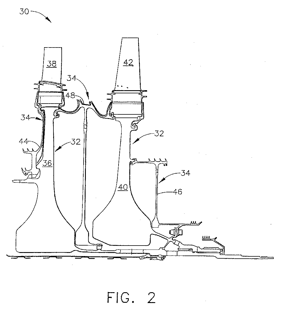
- Figure 2 schematically illustrates a stage 1 turbine disk 36, a stage 1 turbine blade 38 mounted to the stage 1 turbine disk 36, a stage 2 turbine disk 40, a stage 2 turbine blade 42 mounted to the stage 2 turbine disk 40, a forward seal 44, an aft seal 46, and an interstage seal 48.
- Any or all of these turbine disks 32 and/or turbine seal elements 34 may be provided for coating by the present approach, depending upon whether corrosion by the hot combustion gases is expected or observed. In a typical case, only a portion of the selected turbine component 30 is coated. The turbine blades 38 and 42 are not coated by the present approach.
- the turbine component is preferably made of a nickel-base alloy, most preferably a nickel-base superalloy.
- a nickel-base alloy has more nickel than any other element.
- a nickel-base superalloy is strengthened by the precipitation of gamma prime or a related phase.
- a nickel-base superalloy of interest is Rene 88, a known alloy having a nominal composition, in weight percent, of 13 percent cobalt, 16 percent chromium, 4 percent molybdenum, 3.7 percent titanium, 2.1 percent aluminum, 4 percent tungsten, 0.70 percent niobium, 0.015 percent boron, 0.03 percent zirconium, 0.03 percent carbon, balance nickel and minor impurities.
- FIG. 3 illustrates the oxide coating 60 deposited upon a surface 62 of the gas turbine component 30, which thereby serves as a substrate 64 for the oxide coating 60.
- the oxide coating 60 is typically deposited upon the surfaces 62 of those portions of the gas turbine component 60 that experience a service operating temperature of from about 1000°F to about 1400°F.
- the oxide coating 60 is preferably not needed on those portions, such as the portions of the turbine disk 32 near the center bore, whose service operating temperature is less than about 1000°F, because the natural oxidation and corrosion resistance of the materials of construction provide sufficient resistance. In that case, the oxide coating 60 is an unnecessary weight and expense.
- the oxide coating 60 is typically not used on those portions whose service operating temperature is greater than about 1400°F, because the oxide coating has a tendency to spall and fail at these higher temperatures. More complex protective coatings, such as aluminide diffusion or overlay coatings, and optionally thermal barrier coatings, are required at such higher temperatures.
- the present thin oxide coatings are designed to provide oxidation and corrosion protection in the indicated intermediate-temperature range.
- the oxide coating 60 is deposited by a vapor deposition process, most preferably a metal organic chemical vapor deposition (MOCVD) process.
- Figure 4 illustrates an MOCVD apparatus 70 in which such an MOCVD deposition may be performed.
- MOCVD deposition procedures and deposition apparatus are known for other applications, and the following is a brief description of the essential elements.
- the MOCVD apparatus 70 includes a deposition chamber 72 in which the gas turbine component 30 to be coated is placed. Those portions of the gas turbine component 30 that are not to be coated are masked prior to placement in the deposition chamber 72.
- the deposition chamber 72 is heated to the desired deposition temperature by appropriate heaters 74, such as resistance elements.
- the component 30 upon which the oxide coating 60 is deposited is heated to a relatively low temperature during the deposition process.
- the gas turbine components 30 are typically forged or otherwise mechanically worked alloys, which are subject to heat treatments, peening, and other processing to attain very specific microstructures and other structures that are beneficial to their subsequent functionality. A high deposition temperature would adversely affect this structure.
- the deposition temperature to which the gas turbine component 30 must be heated in the deposition chamber 72 depends upon the material being deposited. In many cases, however, that deposition temperature is in the range of about 750-950°F, below the expected service operating temperature of the coated portion of the gas turbine component 30. In some cases of particular oxide coatings 60, the deposition temperatures are necessarily higher, and these higher deposition temperatures are used only with care and consideration to avoid adverse effects on the underlying gas turbine component 30.
- the reagents 76 that produce a deposition vapor are placed into a reagent source chamber 78 that is heated by heaters 80.
- the reagents 76 are organic chemical compounds that contain the elements to be deposited. Some examples of materials that may be carried as organic vapors that also contain oxygen and may deposited by this approach as their oxides include aluminum, silicon, tantalum, titanium, and chromium. Examples of organic chemical compounds that may be used to transport such materials will be discussed subsequently.
- the reagents 76 produce an organic vapor that contains and transports the metal and all other elements needed to form the oxide coating 60.
- the vapor produced from the reagent source chamber 78 flows to the deposition chamber 72 and thence around the gas turbine component 30 to deposit upon its surface 62.
- Another important feature of the MOCVD process is that it is a non-line-of-sight process.
- the metal-bearing vapors flow around the article being coated, reaching regions that are not readily accessible by line-of-sight deposition processes.
- the deposition 22 is normally conducted in a reduced-pressure environment, so that the deposition chamber 72 is provided as a vacuum chamber.
- a vacuum pump 82 is provided to evacuate the deposition chamber 72 as needed.
- a trap 84 traps, filters, and condenses the released organic vapors that are removed from the deposition chamber 72 either directly or by the vacuum pump 82.
- a thickness t of the oxide coating 60 ( Figure 3) is determined in part by the nature of the metal organic vapor, the temperature of deposition, and the time of exposure of the gas turbine component 30 to the metal organic vapor.
- the thickness t of the oxide coating 60 is typically from about 0.2 to about 50 micrometers. More preferably, the thickness t of the oxide coating 60 is from about 0.5 to about 3 micrometers. It is preferred that the oxide coating 60 be relatively thin, as thicker oxide coatings 60 tend to debond from the surface 62 and spall away during repeated thermal cycles between room temperature and the service operating temperature.
- the oxide coating 60 is too thin, such as less than about 0.2 micrometers, there may be incomplete coverage of the surface 62 (i.e., bare spots) and insufficient thickness to resist oxidation and corrosion of the protected substrate 64. If the oxide coating 60 is too thick, there is a tendency for it to debond and spall away from the surface. Studies have determined that the thickness of the oxide coating in the range of about 0.5-3 micrometers, most preferably about 1-2 micrometers, is preferred, providing a balance of good adhesion of the oxide coating 60 to the surface 62 and good protection of the substrate 64.
- the present approach has been practiced using simulated turbine component hardware, following the procedure of Figure 1 and using the apparatus of Figure 4, to produce coated articles as in Figure 3.
- the deposited oxides, their source reagents, their deposition temperatures, and their deposition pressures for these depositions are as follows: (1) aluminum oxide, deposited from aluminum tri-isopropoxide, also known as Al(OPr) 3 , metal organic vapor at 790°F and 100 mtorr partial pressure plus 1 torr nitrogen partial pressure; (2) titanium oxide, deposited from titanium tetra-ethoxide, also known as Ti(OEt) 4 , metal organic vapor at 800°F and 150 mtorr partial pressure; (3) tantalum oxide, deposited from tantalum penta-ethoxide, also known as Ta(OEt) 5 , metal organic vapor at 800°F and 120 mtorr partial pressure; and (4) silica, deposited from silicon tetraethoxide, also known as Si(OEt) 4 , metal organic
- MOCVD Metal-organic chemical vapor deposition
- the invention has been reduced to practice and demonstrated to yield results superior to those of uncoated articles.
Landscapes
- Chemical & Material Sciences (AREA)
- Engineering & Computer Science (AREA)
- Materials Engineering (AREA)
- Mechanical Engineering (AREA)
- General Engineering & Computer Science (AREA)
- Inorganic Chemistry (AREA)
- General Chemical & Material Sciences (AREA)
- Chemical Kinetics & Catalysis (AREA)
- Metallurgy (AREA)
- Organic Chemistry (AREA)
- Chemical Vapour Deposition (AREA)
Abstract
Description
- This invention relates to a gas turbine component and, more particularly, to the protection of the gas turbine component against environmental attack during service, using an oxide coating.
- In an aircraft gas turbine (jet) engine, air is drawn into the front of the engine, compressed by a shaft-mounted compressor, and mixed with fuel. The mixture is burned, and the hot combustion gases are passed through a turbine mounted on the same shaft. The flow of combustion gas turns the turbine, which turns the shaft and provides power to the compressor and to the fan. In a more complex version of the gas-turbine engine, the compressor and a high-pressure turbine are mounted on one shaft having a first set of turbines, and the fan and a low-pressure turbine are mounted on a separate shaft having a second set of turbines. The hot exhaust gases and the air propelled by the fan flow from the back of the engine, driving it and the aircraft forward. The hotter the combustion and exhaust gases, the more efficient is the operation of the jet engine. There is thus an incentive to raise the combustion-gas temperature.
- The turbine includes one or more turbine disks (sometimes termed "turbine rotors"), a number of turbine blades mounted to the turbine disks and extending radially outwardly therefrom into the combustion-gas flow path, and rotating turbine seal elements that prevent the hot combustion gases from contacting the turbine shaft and related components. The maximum operating temperature of the combustion gas is limited by the materials used in the turbine. Great efforts have been made to increase the temperature capabilities of the turbine blades, resulting in increasing combustion gas operating temperatures and increased engine efficiency.
- As the maximum operating temperature of the combustion gas increases, the turbine disks and turbine seal elements are subjected to higher temperatures in the combustion-gas environment. As a result, oxidation and corrosion of the turbine disks and turbine seal elements have become of greater concern.
- Alkaline sulfate deposits resulting from the ingested dirt and the sulfur in the combustion gas are a major source of the corrosion, but other elements in the aggressive combustion-and bleed gas environment may also accelerate the corrosion. The oxidation and corrosion damage may lead to premature removal and replacement of the turbine disks and turbine seal elements unless the damage is reduced or repaired.
- The turbine disks and turbine seal elements for use at the highest operating temperatures are made of nickel-base superalloys selected for good toughness and fatigue resistance. These superalloys are selected for their mechanical properties. They have some resistance to oxidation and corrosion damage, but that resistance is not sufficient to protect them at the operating temperatures that are now being reached.
- The current state of the art is to operate the turbine disks and turbine seal elements without any coatings to protect them against oxidation and corrosion. At the same time, a number of oxidation-resistant and corrosion-resistant coatings have been considered for use on the turbine blades. These available turbine-blade coatings are generally too thick and heavy for use on the turbine disks and turbine seal elements and also may adversely affect the fatigue life of the turbine disks and turbine seal elements. There remains a need for an approach for protecting turbine disks and turbine seal elements against oxidation and corrosion as the operating-temperature requirements of the turbine disks and turbine seal elements increase. This need extends to other components of the gas turbine engine that operate in similar temperature ranges, as well. The present invention fulfills this need, and further provides related advantages.
- The present invention provides a method for protecting a gas turbine component used at a moderately elevated service operating temperature. The approach allows the mechanical performance of the gas turbine component to be optimized using the best available alloy. The selected alloy is protected against environmental damage using a protective coating that is applied at a relatively low temperature. The protective coating is highly adherent, does not adversely affect the properties of the underlying base metal, and is so thin that it does not significantly alter the dimensions of the article to which it is applied. The protective coating is also readily reconditioned and repaired if necessary.
- A method for protecting a gas turbine component comprises the steps of providing the gas turbine component, and depositing an oxide coating on the gas turbine component by vapor deposition.
- The gas turbine component may be of any type, but the present approach is particularly advantageous when used to protect gas turbine components or portions thereof that experience a service operating temperature of from about 1000°F to about 1400°F. Examples of particular interest include all or part of a turbine disk or a turbine seal element. The entire gas turbine component need not be protected in many cases. For example, the mid-to-outer portion of the hub of the turbine disk may be coated, while the bore region, inner portion of the hub, and blade slots may or may not be coated.
- The oxide coating is preferably deposited by metal organic chemical vapor deposition (MOCVD). The MOCVD process is a non-line-of-sight process, in which the deposited oxide is deposited upon portions of the substrate that are not visible from an external source, ensuring complete coverage and protection. The MOCVD process operates for many deposited oxides at relatively low substrate temperatures in the range of about 750-950°F. Achieving acceptable deposition at the low deposition temperature is desirable, because the substantially higher temperatures required for many other coating-formation processes would adversely affect the structure of the substrate gas turbine component. At higher coating temperatures, there is the potential for undesirable reductions in shot peening effects and also part distortions due to residual stresses. The service temperatures of turbine disk alloys are typically from about 1100°F to about 1400°F, and it is therefore desirable to perform any coating at temperatures below this range. Examples of oxides that are readily and desirably deposited by MOCVD include the oxide of a material selected from the group consisting of aluminum, silicon, tantalum, titanium, and chromium. All of these oxides may be deposited by MOCVD at temperatures below these ranges, except for silica. MOCVD deposition of silica is performed at temperatures within this range, and care is taken to keep the deposition time as short as possible. MOCVD may be used to deposit the oxide coating in a thickness of from about 0.2 to about 50 micrometers, although it is preferred that the oxide coating have a thickness of from about 0.5 to about 3 micrometers.
- The present approach "deposits" the coating as an oxide, rather than "grows" the coating, a key advantage. Oxide coatings may be grown on a substrate simply by exposing the substrate to an oxidizing environment, either as part of the manufacturing operation or in service. The oxide coatings that are grown by exposure are of an undefined chemical and physical character, and typically include a mixture of oxides determined by the nature of the substrate material. The thickness of the oxide coating is difficult to control with precision.
- In the present approach, on the other hand, the oxide coating is deposited in its final form, rather than being dependent upon processing and/or service exposure. The oxide coating is of a well-defined composition based upon the selection of the source reactants, and the composition is largely independent of the underlying composition of the substrate component upon which it is deposited. The oxide coating is of a well-defined type due to the source reactants and the deposition conditions. The oxide coating is deposited to a well-defined thickness and is substantially uniform (or controllably nonuniform) throughout the thickness. The oxide coating is stable at the service temperatures reached by the articles such as gas turbine disks. The protective coating may be readily re-deposited or repaired in reconditioning operations.
- The invention will now be described in greater detail, by way of example, with reference to the drawings, in which:-
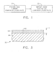
- Figure 1 is a block flow diagram of an approach for practicing the invention;
- Figure 2 is a schematic view of a portion of the turbine section of a gas turbine engine;
- Figure 3 is a schematic view of an oxide protective coating deposited upon a component substrate; and
- Figure 4 is a schematic view of an MOCVD apparatus.
-
- Figure 1 depicts a preferred approach for practicing the invention. A
gas turbine component 30, an example of which is illustrated in Figure 2, is provided,step 20. Thegas turbine component 30 may be of any operable type. Thegas turbine component 30 may be, for example, aturbine disk 32 or aturbine seal element 34. Figure 2 schematically illustrates a stage 1turbine disk 36, a stage 1turbine blade 38 mounted to the stage 1turbine disk 36, a stage 2turbine disk 40, a stage 2turbine blade 42 mounted to the stage 2turbine disk 40, aforward seal 44, anaft seal 46, and aninterstage seal 48. Any or all of theseturbine disks 32 and/orturbine seal elements 34 may be provided for coating by the present approach, depending upon whether corrosion by the hot combustion gases is expected or observed. In a typical case, only a portion of theselected turbine component 30 is coated. Theturbine blades - The turbine component is preferably made of a nickel-base alloy, most preferably a nickel-base superalloy. A nickel-base alloy has more nickel than any other element. A nickel-base superalloy is strengthened by the precipitation of gamma prime or a related phase. A nickel-base superalloy of interest is Rene 88, a known alloy having a nominal composition, in weight percent, of 13 percent cobalt, 16 percent chromium, 4 percent molybdenum, 3.7 percent titanium, 2.1 percent aluminum, 4 percent tungsten, 0.70 percent niobium, 0.015 percent boron, 0.03 percent zirconium, 0.03 percent carbon, balance nickel and minor impurities.
- An oxide coating is deposited upon the
gas turbine component 30 by vapor deposition, step 22 of Figure 1. Figure 3 illustrates theoxide coating 60 deposited upon asurface 62 of thegas turbine component 30, which thereby serves as asubstrate 64 for theoxide coating 60. - The
oxide coating 60 is typically deposited upon thesurfaces 62 of those portions of thegas turbine component 60 that experience a service operating temperature of from about 1000°F to about 1400°F. Theoxide coating 60 is preferably not needed on those portions, such as the portions of theturbine disk 32 near the center bore, whose service operating temperature is less than about 1000°F, because the natural oxidation and corrosion resistance of the materials of construction provide sufficient resistance. In that case, theoxide coating 60 is an unnecessary weight and expense. Theoxide coating 60 is typically not used on those portions whose service operating temperature is greater than about 1400°F, because the oxide coating has a tendency to spall and fail at these higher temperatures. More complex protective coatings, such as aluminide diffusion or overlay coatings, and optionally thermal barrier coatings, are required at such higher temperatures. The present thin oxide coatings are designed to provide oxidation and corrosion protection in the indicated intermediate-temperature range. - The
oxide coating 60 is deposited by a vapor deposition process, most preferably a metal organic chemical vapor deposition (MOCVD) process.
Figure 4 illustrates anMOCVD apparatus 70 in which such an MOCVD deposition may be performed. MOCVD deposition procedures and deposition apparatus are known for other applications, and the following is a brief description of the essential elements. TheMOCVD apparatus 70 includes adeposition chamber 72 in which thegas turbine component 30 to be coated is placed. Those portions of thegas turbine component 30 that are not to be coated are masked prior to placement in thedeposition chamber 72. Thedeposition chamber 72 is heated to the desired deposition temperature byappropriate heaters 74, such as resistance elements. - An important feature of the MOCVD process is that the
component 30 upon which theoxide coating 60 is deposited is heated to a relatively low temperature during the deposition process. Thegas turbine components 30 are typically forged or otherwise mechanically worked alloys, which are subject to heat treatments, peening, and other processing to attain very specific microstructures and other structures that are beneficial to their subsequent functionality. A high deposition temperature would adversely affect this structure. The deposition temperature to which thegas turbine component 30 must be heated in thedeposition chamber 72 depends upon the material being deposited. In many cases, however, that deposition temperature is in the range of about 750-950°F, below the expected service operating temperature of the coated portion of thegas turbine component 30. In some cases ofparticular oxide coatings 60, the deposition temperatures are necessarily higher, and these higher deposition temperatures are used only with care and consideration to avoid adverse effects on the underlyinggas turbine component 30. - The
reagents 76 that produce a deposition vapor are placed into areagent source chamber 78 that is heated byheaters 80. Thereagents 76 are organic chemical compounds that contain the elements to be deposited. Some examples of materials that may be carried as organic vapors that also contain oxygen and may deposited by this approach as their oxides include aluminum, silicon, tantalum, titanium, and chromium. Examples of organic chemical compounds that may be used to transport such materials will be discussed subsequently. Thereagents 76 produce an organic vapor that contains and transports the metal and all other elements needed to form theoxide coating 60. - The vapor produced from the
reagent source chamber 78 flows to thedeposition chamber 72 and thence around thegas turbine component 30 to deposit upon itssurface 62. Another important feature of the MOCVD process is that it is a non-line-of-sight process. The metal-bearing vapors flow around the article being coated, reaching regions that are not readily accessible by line-of-sight deposition processes. - The
deposition 22 is normally conducted in a reduced-pressure environment, so that thedeposition chamber 72 is provided as a vacuum chamber. Avacuum pump 82 is provided to evacuate thedeposition chamber 72 as needed. Atrap 84 traps, filters, and condenses the released organic vapors that are removed from thedeposition chamber 72 either directly or by thevacuum pump 82. - A thickness t of the oxide coating 60 (Figure 3) is determined in part by the nature of the metal organic vapor, the temperature of deposition, and the time of exposure of the
gas turbine component 30 to the metal organic vapor. The thickness t of theoxide coating 60 is typically from about 0.2 to about 50 micrometers. More preferably, the thickness t of theoxide coating 60 is from about 0.5 to about 3 micrometers. It is preferred that theoxide coating 60 be relatively thin, asthicker oxide coatings 60 tend to debond from thesurface 62 and spall away during repeated thermal cycles between room temperature and the service operating temperature. If theoxide coating 60 is too thin, such as less than about 0.2 micrometers, there may be incomplete coverage of the surface 62 (i.e., bare spots) and insufficient thickness to resist oxidation and corrosion of the protectedsubstrate 64. If theoxide coating 60 is too thick, there is a tendency for it to debond and spall away from the surface. Studies have determined that the thickness of the oxide coating in the range of about 0.5-3 micrometers, most preferably about 1-2 micrometers, is preferred, providing a balance of good adhesion of theoxide coating 60 to thesurface 62 and good protection of thesubstrate 64. - The present approach has been practiced using simulated turbine component hardware, following the procedure of Figure 1 and using the apparatus of Figure 4, to produce coated articles as in Figure 3. The deposited oxides, their source reagents, their deposition temperatures, and their deposition pressures for these depositions are as follows: (1) aluminum oxide, deposited from aluminum tri-isopropoxide, also known as Al(OPr)3, metal organic vapor at 790°F and 100 mtorr partial pressure plus 1 torr nitrogen partial pressure; (2) titanium oxide, deposited from titanium tetra-ethoxide, also known as Ti(OEt)4, metal organic vapor at 800°F and 150 mtorr partial pressure; (3) tantalum oxide, deposited from tantalum penta-ethoxide, also known as Ta(OEt)5, metal organic vapor at 800°F and 120 mtorr partial pressure; and (4) silica, deposited from silicon tetraethoxide, also known as Si(OEt)4, metal organic vapor at 1275°F and 500 mtorr vapor. Silicon and other elements which are not strictly metals are included in the group of elements that may be deposited by MOCVD, and are included as "metals" herein. One of the features of MOCVD is that different ones of the reagents may be simultaneously provided in one or more
reagent source chambers 78, vaporized, and co-deposited to formoxide coatings 60 of a complex oxide composition. - The invention has been reduced to practice and demonstrated to yield results superior to those of uncoated articles.
Claims (13)
- A method for protecting a gas turbine component (30), comprising the steps of
providing the gas turbine component (30); and
depositing an oxide coating (60) upon the gas turbine component (30) by vapor deposition. - The method of claim 1, wherein the step of providing the gas turbine component (30) includes the step of providing a turbine disk (36, 40).
- The method of claim 1, wherein the step of providing the gas turbine component (30) includes the step of providing a turbine seal element (44, 46, 48).
- The method of claim 1, wherein the step of depositing the oxide coating (60) includes the step of depositing the oxide coating (60) on a portion of the gas turbine component (30) having a service operating temperature of from about 1000°F to about 1400°F.
- The method of claim 1, wherein the step of depositing the oxide coating (60) includes the step of depositing the oxide coating (60) by metal organic chemical vapor deposition.
- The method of claim 1, wherein the step of depositing the oxide coating (60) includes the step of depositing the oxide coating (60) of an oxide of a material selected from the group consisting of aluminum, silicon, tantalum, titanium, and chromium.
- The method of claim 1, wherein the step of depositing the oxide coating (60) includes the step of depositing the oxide coating (60) in a thickness of from about 0.2 to about 50 micrometers.
- The method of claim 1, wherein the step of depositing the oxide coating (60) includes the step of depositing the oxide coating (60) in a thickness of from about 0.5 to about 3 micrometers.
- A method for protecting a gas turbine component (30), comprising the steps of
providing the gas turbine component (30) selected from the group consisting of a turbine disk (36, 40) and a turbine seal element (44, 46, 48); and
depositing an oxide coating (60) upon the gas turbine component (30) by metal-organic chemical vapor deposition, the oxide coating (60) having a thickness of from about 0.2 to about 50 micrometers. - The method of claim 9, wherein the step of depositing the oxide coating (60) includes the step of depositing the oxide coating (60) on a portion of the gas turbine component (30) having a service operating temperature of from about 1000°F to about 1400°F.
- The method of claim 9, wherein the step of depositing the oxide coating (60) includes the step of depositing the oxide coating (60) of an oxide of a material selected from the group consisting of aluminum, silicon, tantalum, titanium, and chromium.
- The method of claim 9, wherein the step of depositing the oxide coating (60) includes the step of depositing the oxide coating (60) in a thickness of from about 0.5 to about 3 micrometers.
- A method for protecting a gas turbine component (30), comprising the steps of
providing the gas turbine component (30), the gas turbine component (30) being selected from the group consisting of a turbine disk (36, 40) and a turbine seal element (44, 46, 48); and
depositing an oxide coating (60) upon a portion of the gas turbine component (30) having a service operating temperature of from about 1000°F to about 1400°F, the step of depositing the oxide coating (60) including the step of
depositing the oxide coating (60) by metal-organic chemical vapor deposition, the oxide coating (60) having a thickness of from about 0.5 to about 3 micrometers and comprising an oxide of a material selected from the group consisting of aluminum, silicon, tantalum, titanium, and chromium.
Applications Claiming Priority (2)
| Application Number | Priority Date | Filing Date | Title |
|---|---|---|---|
| US10/199,185 US6926928B2 (en) | 2002-07-19 | 2002-07-19 | Protection of a gas turbine component by a vapor-deposited oxide coating |
| US199185 | 2002-07-19 |
Publications (2)
| Publication Number | Publication Date |
|---|---|
| EP1382715A1 true EP1382715A1 (en) | 2004-01-21 |
| EP1382715B1 EP1382715B1 (en) | 2013-09-04 |
Family
ID=29780225
Family Applications (1)
| Application Number | Title | Priority Date | Filing Date |
|---|---|---|---|
| EP03254490.0A Expired - Lifetime EP1382715B1 (en) | 2002-07-19 | 2003-07-18 | Protection of a gas turbine component by a vapor-deposited oxide coating |
Country Status (3)
| Country | Link |
|---|---|
| US (1) | US6926928B2 (en) |
| EP (1) | EP1382715B1 (en) |
| SG (1) | SG109518A1 (en) |
Cited By (2)
| Publication number | Priority date | Publication date | Assignee | Title |
|---|---|---|---|---|
| EP2141263A3 (en) * | 2008-06-24 | 2010-03-17 | General Electric Company | Alloy castings having protective layers and methods of making the same |
| EP1512839A3 (en) * | 2003-09-05 | 2012-08-01 | General Electric Company | Aluminide or chromide coating of turbine engine rotor component |
Families Citing this family (21)
| Publication number | Priority date | Publication date | Assignee | Title |
|---|---|---|---|---|
| US7455890B2 (en) | 2003-08-05 | 2008-11-25 | General Electric Company | Ion implantation of turbine engine rotor component |
| US20050255329A1 (en) * | 2004-05-12 | 2005-11-17 | General Electric Company | Superalloy article having corrosion resistant coating thereon |
| US7314674B2 (en) * | 2004-12-15 | 2008-01-01 | General Electric Company | Corrosion resistant coating composition, coated turbine component and method for coating same |
| US7601400B2 (en) * | 2005-03-10 | 2009-10-13 | General Electric Company | Liquid electrostatic coating composition comprising corrosion resistant metal particulates and method for using same |
| US7544396B2 (en) * | 2005-03-10 | 2009-06-09 | General Electric Company | Electrostatic coating composition comprising corrosion resistant metal particulates and method for using same |
| US7666515B2 (en) * | 2005-03-31 | 2010-02-23 | General Electric Company | Turbine component other than airfoil having ceramic corrosion resistant coating and methods for making same |
| US7311940B2 (en) * | 2005-11-04 | 2007-12-25 | General Electric Company | Layered paint coating for turbine blade environmental protection |
| US7780832B2 (en) * | 2005-11-30 | 2010-08-24 | General Electric Company | Methods for applying mitigation coatings, and related articles |
| US7955694B2 (en) * | 2006-06-21 | 2011-06-07 | General Electric Company | Strain tolerant coating for environmental protection |
| US20090239061A1 (en) * | 2006-11-08 | 2009-09-24 | General Electric Corporation | Ceramic corrosion resistant coating for oxidation resistance |
| US7364801B1 (en) | 2006-12-06 | 2008-04-29 | General Electric Company | Turbine component protected with environmental coating |
| US20090098394A1 (en) * | 2006-12-26 | 2009-04-16 | General Electric Company | Strain tolerant corrosion protecting coating and tape method of application |
| US20100052261A1 (en) * | 2008-09-03 | 2010-03-04 | Salvador Maldonado | Metallic seal for use in highly-corrosive oil and gas environments |
| US9719353B2 (en) | 2011-04-13 | 2017-08-01 | Rolls-Royce Corporation | Interfacial diffusion barrier layer including iridium on a metallic substrate |
| US9145786B2 (en) | 2012-04-17 | 2015-09-29 | General Electric Company | Method and apparatus for turbine clearance flow reduction |
| CA2904185C (en) | 2013-03-13 | 2021-02-23 | General Electric Company | Coatings for metallic substrates |
| US10266958B2 (en) * | 2013-12-24 | 2019-04-23 | United Technologies Corporation | Hot corrosion-protected articles and manufacture methods |
| EP2918705B1 (en) | 2014-03-12 | 2017-05-03 | Rolls-Royce Corporation | Coating including diffusion barrier layer including iridium and oxide layer and method of coating |
| US10280770B2 (en) | 2014-10-09 | 2019-05-07 | Rolls-Royce Corporation | Coating system including oxide nanoparticles in oxide matrix |
| US10047614B2 (en) | 2014-10-09 | 2018-08-14 | Rolls-Royce Corporation | Coating system including alternating layers of amorphous silica and amorphous silicon nitride |
| US11473197B2 (en) * | 2018-03-16 | 2022-10-18 | Raytheon Technologies Corporation | HPC and HPT disks coated by atomic layer deposition |
Citations (6)
| Publication number | Priority date | Publication date | Assignee | Title |
|---|---|---|---|---|
| US3907311A (en) * | 1974-04-15 | 1975-09-23 | Ford Motor Co | High temperature, low friction ceramic coating for gas turbine regenerator seals |
| GB2126572A (en) * | 1982-09-02 | 1984-03-28 | Maschf Augsburg Nuernberg Ag | Corrosion resistant alumina layer on metallic substrates |
| WO1994029237A1 (en) * | 1993-06-11 | 1994-12-22 | United Technologies Corporation | Ceramic material and insulating coating made thereof |
| EP0666407A2 (en) * | 1993-12-08 | 1995-08-09 | ROLLS-ROYCE plc | Integrally bladed discs or drums |
| WO1996031293A1 (en) * | 1995-04-03 | 1996-10-10 | General Electric Company | Method and composite for protection of thermal barrier coating by a sacrificial surface coating |
| EP1201778A2 (en) * | 2000-10-30 | 2002-05-02 | United Technologies Corporation | Low density oxidation resistant superalloy materials capable of thermal barrier coating retention without a bond coat |
Family Cites Families (7)
| Publication number | Priority date | Publication date | Assignee | Title |
|---|---|---|---|---|
| GB2081246B (en) * | 1980-07-25 | 1984-03-14 | Rolls Royce | Thermal barrier coating composition |
| US5073433B1 (en) * | 1989-10-20 | 1995-10-31 | Praxair Technology Inc | Thermal barrier coating for substrates and process for producing it |
| US5660885A (en) * | 1995-04-03 | 1997-08-26 | General Electric Company | Protection of thermal barrier coating by a sacrificial surface coating |
| EP0780484B1 (en) * | 1995-12-22 | 2001-09-26 | General Electric Company | Thermal barrier coated articles and method for coating |
| US5900283A (en) * | 1996-11-12 | 1999-05-04 | General Electric Company | Method for providing a protective coating on a metal-based substrate and related articles |
| US6532657B1 (en) * | 2001-09-21 | 2003-03-18 | General Electric Co., | Pre-service oxidation of gas turbine disks and seals |
| US6663919B2 (en) * | 2002-03-01 | 2003-12-16 | General Electric Company | Process of removing a coating deposit from a through-hole in a component and component processed thereby |
-
2002
- 2002-07-19 US US10/199,185 patent/US6926928B2/en not_active Expired - Fee Related
-
2003
- 2003-07-11 SG SG200304078A patent/SG109518A1/en unknown
- 2003-07-18 EP EP03254490.0A patent/EP1382715B1/en not_active Expired - Lifetime
Patent Citations (6)
| Publication number | Priority date | Publication date | Assignee | Title |
|---|---|---|---|---|
| US3907311A (en) * | 1974-04-15 | 1975-09-23 | Ford Motor Co | High temperature, low friction ceramic coating for gas turbine regenerator seals |
| GB2126572A (en) * | 1982-09-02 | 1984-03-28 | Maschf Augsburg Nuernberg Ag | Corrosion resistant alumina layer on metallic substrates |
| WO1994029237A1 (en) * | 1993-06-11 | 1994-12-22 | United Technologies Corporation | Ceramic material and insulating coating made thereof |
| EP0666407A2 (en) * | 1993-12-08 | 1995-08-09 | ROLLS-ROYCE plc | Integrally bladed discs or drums |
| WO1996031293A1 (en) * | 1995-04-03 | 1996-10-10 | General Electric Company | Method and composite for protection of thermal barrier coating by a sacrificial surface coating |
| EP1201778A2 (en) * | 2000-10-30 | 2002-05-02 | United Technologies Corporation | Low density oxidation resistant superalloy materials capable of thermal barrier coating retention without a bond coat |
Non-Patent Citations (1)
| Title |
|---|
| WAHL G. ET AL.: "Chemical Vapor Deposition of TBC: An Alternative Process for Gas Turbine Components", JOURNAL OF ENGINEERING FOR GAS TURBINES AND POWER, vol. 123, no. 3, July 2001 (2001-07-01), pages 520 - 524, XP009016678 * |
Cited By (2)
| Publication number | Priority date | Publication date | Assignee | Title |
|---|---|---|---|---|
| EP1512839A3 (en) * | 2003-09-05 | 2012-08-01 | General Electric Company | Aluminide or chromide coating of turbine engine rotor component |
| EP2141263A3 (en) * | 2008-06-24 | 2010-03-17 | General Electric Company | Alloy castings having protective layers and methods of making the same |
Also Published As
| Publication number | Publication date |
|---|---|
| US20040013802A1 (en) | 2004-01-22 |
| US6926928B2 (en) | 2005-08-09 |
| EP1382715B1 (en) | 2013-09-04 |
| SG109518A1 (en) | 2005-03-30 |
Similar Documents
| Publication | Publication Date | Title |
|---|---|---|
| EP1382715B1 (en) | Protection of a gas turbine component by a vapor-deposited oxide coating | |
| EP1512839B1 (en) | Method for creating an aluminide or chromide coating of turbine engine rotor component | |
| US6296447B1 (en) | Gas turbine component having location-dependent protective coatings thereon | |
| US6283714B1 (en) | Protection of internal and external surfaces of gas turbine airfoils | |
| EP1595977B1 (en) | Superalloy article having corrosion resistant coating thereon | |
| JP4191427B2 (en) | Improved plasma sprayed thermal bond coat system | |
| CN100408726C (en) | High temperature resistant article and method of making same | |
| US7056555B2 (en) | Method for coating an internal surface of an article with an aluminum-containing coating | |
| US6532657B1 (en) | Pre-service oxidation of gas turbine disks and seals | |
| EP1391531B1 (en) | Process of producing of thermal barrier coating with nitride particles | |
| US7666515B2 (en) | Turbine component other than airfoil having ceramic corrosion resistant coating and methods for making same | |
| US6905730B2 (en) | Aluminide coating of turbine engine component | |
| US20100266417A1 (en) | Bond coat with low deposited aluminum level and method therefore | |
| US7160635B2 (en) | Protective Ti-Al-Cr-based nitrided coatings | |
| EP1215301B1 (en) | Method for treating the bond coating of a component | |
| EP1431416A1 (en) | Protective Ti-Al-Cr-N coating | |
| EP1522607B1 (en) | Method for fabricating a coated superalloy stabilized against the formation of secondary reaction zone | |
| US6933012B2 (en) | Method for protecting a surface with a silicon-containing diffusion coating |
Legal Events
| Date | Code | Title | Description |
|---|---|---|---|
| PUAI | Public reference made under article 153(3) epc to a published international application that has entered the european phase |
Free format text: ORIGINAL CODE: 0009012 |
|
| AK | Designated contracting states |
Kind code of ref document: A1 Designated state(s): AT BE BG CH CY CZ DE DK EE ES FI FR GB GR HU IE IT LI LU MC NL PT RO SE SI SK TR |
|
| AX | Request for extension of the european patent |
Extension state: AL LT LV MK |
|
| RIN1 | Information on inventor provided before grant (corrected) |
Inventor name: SCHAEFFER, JON CONRAD Inventor name: HAHN, JAMES ANDREW Inventor name: NAGARAJ, BANGALORE ASWATHA Inventor name: WEIMER, MICHAEL JAMES Inventor name: HEANY, JOSEPH ALOYSIUS Inventor name: ACKERMAN, JOHN FREDERICK Inventor name: WALSTON, WILLIAM SCOTT |
|
| 17P | Request for examination filed |
Effective date: 20040721 |
|
| AKX | Designation fees paid |
Designated state(s): DE FR GB |
|
| 17Q | First examination report despatched |
Effective date: 20080514 |
|
| RIC1 | Information provided on ipc code assigned before grant |
Ipc: C23C 16/40 20060101AFI20130220BHEP Ipc: F01D 5/28 20060101ALI20130220BHEP |
|
| GRAP | Despatch of communication of intention to grant a patent |
Free format text: ORIGINAL CODE: EPIDOSNIGR1 |
|
| INTG | Intention to grant announced |
Effective date: 20130417 |
|
| GRAS | Grant fee paid |
Free format text: ORIGINAL CODE: EPIDOSNIGR3 |
|
| GRAA | (expected) grant |
Free format text: ORIGINAL CODE: 0009210 |
|
| AK | Designated contracting states |
Kind code of ref document: B1 Designated state(s): DE FR GB |
|
| REG | Reference to a national code |
Ref country code: GB Ref legal event code: FG4D |
|
| REG | Reference to a national code |
Ref country code: DE Ref legal event code: R096 Ref document number: 60344846 Country of ref document: DE Effective date: 20131024 |
|
| REG | Reference to a national code |
Ref country code: DE Ref legal event code: R097 Ref document number: 60344846 Country of ref document: DE |
|
| PLBE | No opposition filed within time limit |
Free format text: ORIGINAL CODE: 0009261 |
|
| STAA | Information on the status of an ep patent application or granted ep patent |
Free format text: STATUS: NO OPPOSITION FILED WITHIN TIME LIMIT |
|
| 26N | No opposition filed |
Effective date: 20140605 |
|
| REG | Reference to a national code |
Ref country code: DE Ref legal event code: R097 Ref document number: 60344846 Country of ref document: DE Effective date: 20140605 |
|
| REG | Reference to a national code |
Ref country code: FR Ref legal event code: PLFP Year of fee payment: 13 |
|
| PGFP | Annual fee paid to national office [announced via postgrant information from national office to epo] |
Ref country code: GB Payment date: 20150727 Year of fee payment: 13 Ref country code: DE Payment date: 20150729 Year of fee payment: 13 |
|
| PGFP | Annual fee paid to national office [announced via postgrant information from national office to epo] |
Ref country code: FR Payment date: 20150717 Year of fee payment: 13 |
|
| REG | Reference to a national code |
Ref country code: DE Ref legal event code: R119 Ref document number: 60344846 Country of ref document: DE |
|
| GBPC | Gb: european patent ceased through non-payment of renewal fee |
Effective date: 20160718 |
|
| PG25 | Lapsed in a contracting state [announced via postgrant information from national office to epo] |
Ref country code: FR Free format text: LAPSE BECAUSE OF NON-PAYMENT OF DUE FEES Effective date: 20160801 Ref country code: DE Free format text: LAPSE BECAUSE OF NON-PAYMENT OF DUE FEES Effective date: 20170201 |
|
| REG | Reference to a national code |
Ref country code: FR Ref legal event code: ST Effective date: 20170331 |
|
| PG25 | Lapsed in a contracting state [announced via postgrant information from national office to epo] |
Ref country code: GB Free format text: LAPSE BECAUSE OF NON-PAYMENT OF DUE FEES Effective date: 20160718 |