EP1382578A1 - Method for the filtration of water and a water filtration device - Google Patents
Method for the filtration of water and a water filtration device Download PDFInfo
- Publication number
- EP1382578A1 EP1382578A1 EP03077217A EP03077217A EP1382578A1 EP 1382578 A1 EP1382578 A1 EP 1382578A1 EP 03077217 A EP03077217 A EP 03077217A EP 03077217 A EP03077217 A EP 03077217A EP 1382578 A1 EP1382578 A1 EP 1382578A1
- Authority
- EP
- European Patent Office
- Prior art keywords
- water
- pump
- pump unit
- water purification
- pressure
- Prior art date
- Legal status (The legal status is an assumption and is not a legal conclusion. Google has not performed a legal analysis and makes no representation as to the accuracy of the status listed.)
- Granted
Links
- XLYOFNOQVPJJNP-UHFFFAOYSA-N water Substances O XLYOFNOQVPJJNP-UHFFFAOYSA-N 0.000 title claims abstract description 333
- 238000000034 method Methods 0.000 title claims abstract description 30
- 238000001914 filtration Methods 0.000 title claims abstract description 18
- 238000000746 purification Methods 0.000 claims abstract description 78
- 238000001816 cooling Methods 0.000 claims abstract description 17
- 239000008213 purified water Substances 0.000 claims description 78
- 239000012141 concentrate Substances 0.000 claims description 14
- 239000002519 antifouling agent Substances 0.000 claims description 8
- 239000002245 particle Substances 0.000 claims description 7
- 238000005273 aeration Methods 0.000 claims description 6
- 230000008878 coupling Effects 0.000 claims description 6
- 238000010168 coupling process Methods 0.000 claims description 6
- 238000005859 coupling reaction Methods 0.000 claims description 6
- 239000000463 material Substances 0.000 claims description 5
- 238000010992 reflux Methods 0.000 claims description 5
- 238000007599 discharging Methods 0.000 claims description 4
- 238000005259 measurement Methods 0.000 claims description 4
- 238000002156 mixing Methods 0.000 claims description 4
- 238000011144 upstream manufacturing Methods 0.000 claims description 3
- 239000003795 chemical substances by application Substances 0.000 claims description 2
- 238000004891 communication Methods 0.000 claims 1
- 238000012544 monitoring process Methods 0.000 claims 1
- 239000002351 wastewater Substances 0.000 description 22
- 238000009434 installation Methods 0.000 description 5
- 238000001223 reverse osmosis Methods 0.000 description 5
- 238000010586 diagram Methods 0.000 description 4
- 238000004519 manufacturing process Methods 0.000 description 4
- 239000007788 liquid Substances 0.000 description 3
- 238000004064 recycling Methods 0.000 description 3
- 230000001105 regulatory effect Effects 0.000 description 3
- OKTJSMMVPCPJKN-UHFFFAOYSA-N Carbon Chemical compound [C] OKTJSMMVPCPJKN-UHFFFAOYSA-N 0.000 description 2
- 230000006978 adaptation Effects 0.000 description 2
- 238000005276 aerator Methods 0.000 description 2
- 238000013016 damping Methods 0.000 description 2
- 230000007547 defect Effects 0.000 description 2
- 238000009429 electrical wiring Methods 0.000 description 2
- 230000017525 heat dissipation Effects 0.000 description 2
- RYGMFSIKBFXOCR-UHFFFAOYSA-N Copper Chemical compound [Cu] RYGMFSIKBFXOCR-UHFFFAOYSA-N 0.000 description 1
- 239000002253 acid Substances 0.000 description 1
- 239000003638 chemical reducing agent Substances 0.000 description 1
- 238000010276 construction Methods 0.000 description 1
- 229910052802 copper Inorganic materials 0.000 description 1
- 239000010949 copper Substances 0.000 description 1
- 230000000694 effects Effects 0.000 description 1
- 239000003344 environmental pollutant Substances 0.000 description 1
- 239000000706 filtrate Substances 0.000 description 1
- JEGUKCSWCFPDGT-UHFFFAOYSA-N h2o hydrate Chemical compound O.O JEGUKCSWCFPDGT-UHFFFAOYSA-N 0.000 description 1
- 238000010438 heat treatment Methods 0.000 description 1
- 238000010348 incorporation Methods 0.000 description 1
- 238000009413 insulation Methods 0.000 description 1
- 239000012528 membrane Substances 0.000 description 1
- 238000001728 nano-filtration Methods 0.000 description 1
- 231100000719 pollutant Toxicity 0.000 description 1
- 230000000717 retained effect Effects 0.000 description 1
- 150000003839 salts Chemical class 0.000 description 1
- 239000004576 sand Substances 0.000 description 1
- 239000008399 tap water Substances 0.000 description 1
- 235000020679 tap water Nutrition 0.000 description 1
- 238000000108 ultra-filtration Methods 0.000 description 1
- 230000003245 working effect Effects 0.000 description 1
Images




Classifications
-
- C—CHEMISTRY; METALLURGY
- C02—TREATMENT OF WATER, WASTE WATER, SEWAGE, OR SLUDGE
- C02F—TREATMENT OF WATER, WASTE WATER, SEWAGE, OR SLUDGE
- C02F9/00—Multistage treatment of water, waste water or sewage
- C02F9/20—Portable or detachable small-scale multistage treatment devices, e.g. point of use or laboratory water purification systems
-
- C—CHEMISTRY; METALLURGY
- C02—TREATMENT OF WATER, WASTE WATER, SEWAGE, OR SLUDGE
- C02F—TREATMENT OF WATER, WASTE WATER, SEWAGE, OR SLUDGE
- C02F1/00—Treatment of water, waste water, or sewage
- C02F1/28—Treatment of water, waste water, or sewage by sorption
- C02F1/283—Treatment of water, waste water, or sewage by sorption using coal, charred products, or inorganic mixtures containing them
-
- C—CHEMISTRY; METALLURGY
- C02—TREATMENT OF WATER, WASTE WATER, SEWAGE, OR SLUDGE
- C02F—TREATMENT OF WATER, WASTE WATER, SEWAGE, OR SLUDGE
- C02F1/00—Treatment of water, waste water, or sewage
- C02F1/44—Treatment of water, waste water, or sewage by dialysis, osmosis or reverse osmosis
- C02F1/441—Treatment of water, waste water, or sewage by dialysis, osmosis or reverse osmosis by reverse osmosis
-
- C—CHEMISTRY; METALLURGY
- C02—TREATMENT OF WATER, WASTE WATER, SEWAGE, OR SLUDGE
- C02F—TREATMENT OF WATER, WASTE WATER, SEWAGE, OR SLUDGE
- C02F1/00—Treatment of water, waste water, or sewage
- C02F1/44—Treatment of water, waste water, or sewage by dialysis, osmosis or reverse osmosis
- C02F1/444—Treatment of water, waste water, or sewage by dialysis, osmosis or reverse osmosis by ultrafiltration or microfiltration
-
- C—CHEMISTRY; METALLURGY
- C02—TREATMENT OF WATER, WASTE WATER, SEWAGE, OR SLUDGE
- C02F—TREATMENT OF WATER, WASTE WATER, SEWAGE, OR SLUDGE
- C02F1/00—Treatment of water, waste water, or sewage
- C02F1/66—Treatment of water, waste water, or sewage by neutralisation; pH adjustment
Definitions
- the present invention relates to a method for the filtration of feed water with a filtering unit, wherein by means of a pump unit, comprising a drive and a pump provided with a pump housing, a water inlet opening and a water outlet opening, feed water is fed through the water inlet opening to the pump and is fed through the pump's water outlet opening to the filter unit and filtered.
- a pump unit comprising a drive and a pump provided with a pump housing, a water inlet opening and a water outlet opening, feed water is fed through the water inlet opening to the pump and is fed through the pump's water outlet opening to the filter unit and filtered.
- the invention also relates to a water purification device for the purification of water, comprising: at least one filter unit for filtering water, one pump unit, comprising a drive and a pump provided with a water inlet opening for feeding feed water to the pump and a water outlet opening for at elevated pressure discharging discharge water from the pump, pipe means connected to the water outlet opening of the pump for under elevated pressure feeding discharge water from the pump to the filter unit, and cooling provisions for cooling the pump unit.
- the purification of water in accordance with the method mentioned in the preamble is generally known in the art.
- devices for the purification of water that are suitable, for example, for the above-mentioned method are also generally known in the art.
- a disadvantage of the known water purification system is that the heat generated by, for example, the pump and by the drive means is directly dissipated to the environment. For this reason the known installations must at all times be placed in a ventilated room.
- Another disadvantage is the noise production of the known purification systems. Both the pumps and the drive means generate much noise, which makes it necessary to take sound-damping measures.
- the object of the present invention is to provide an improved method and an improved device with which the drawbacks of the prior art systems are avoided.
- the object of the invention is in particular to provide an improved method and an improved device with which the heat dissipation to the environment is reduced.
- Another particular object of the invention is to provide an improved method and an improved device with which the noise production can be reduced considerably.
- the invention provides a method as mentioned in the preamble and which is characterised in that the feed water is fed to the exterior of the pump for the purpose of cooling the pump.
- This makes it possible to place the pump into the feed water to be filtered so that heat is not dissipated to the environment but to the water to be filtered. Since the water to be filtered is conducted onward for use, the heat will not be dissipated directly to the immediate environment. This considerably reduces the heating of the atmosphere in the vicinity of the conduit means.
- An additional consequence of the invention is that the noise generation to the environment is significantly reduced since water has a very strongly damping effect.
- the noise reduction obtained with the method according to the invention is substantial. It is particularly preferred for the pump unit to be at least partly submerged in the feed water and to dissipate heat thereto. It is especially such an embodiment with which the advantages of the invention can be obtained in a particularly efficient manner.
- the method is characterised in that:
- Such a first filter may be placed either before or after the pump unit. It is preferred for the first filter to be placed in a position before the pump unit. When tap water is subjected to a method according to the invention, such a first filter will ensure that the coarsest particles are removed from the water to be filtered before feeding to the final filter unit. It is particularly preferred for the filter unit to be formed by a reverse osmosis unit. Such a reverse osmosis unit is very suitable, for example, for completely or partly removing dissolved salts from the water.
- the invention is characterised in that any gasses, such as air, in the container are removed by de-aeration. This ensures that the pump unit will at all times be below the feed water level. This provides effective cooling of the unit.
- the pump unit consists of an under water pump, which is entirely accommodated inside the container. In such an embodiment both the pump and its drive are placed in the feed water. In this manner both the dissipation of heat and the reduction of the noise produced is optimal.
- the method is characterised in that:
- Such a method is especially very suitable for using in a system wherein an expansion tank is employed for the storage of purified water.
- the method according to the invention is preferably characterised in that:
- the invention also relates to a water purification device for the purification of water.
- the water purification device according to the invention is characterised in that the same comprises: at least one filter unit for filtering water,
- Such a water purification device is especially, but not exclusively useful in the method according to the invention. With such a water purification device the objectives mentioned above can be realised.
- the cooling provisions comprise at least one container, which surrounds the pump unit at least partly and can at least partly be filled with feed water. This affords the possibility to keep the pump unit completely or partly below the liquid level for the dissipation of heat and to reduce the noise production into the environment. It is then especially preferred for the holder to comprise a closed tank that is suitable to at least partly be filled with feed water.
- a further preferred embodiment entails raw-water pipe means through which raw water is fed to the container, and upstream from the container there is a first filter unit for the removal of larger dirt particles from the raw water by means of preliminary filtration of the raw water in the raw-water pipe means.
- Fig. 1 shows a schematic depiction of a water purification device with an expansion tank according to a first embodiment of the invention.
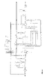
- Fig. 2 shows the device according to Fig. 1 with the electrical wiring diagram.
- Fig. 3 shows a second embodiment of the water purification according to the invention using a storage tank.
- Fig. 4 shows the wiring diagram of the water purification device according to Fig. 3.
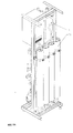
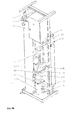
- Figs. 5 to 5B show a number of embodiments of parts of the water purification device according to the invention.
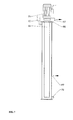
- Fig. 6 shows a first embodiment of a container for use in a device according to the invention.
- Fig. 7 shows a second embodiment of a container for use in the device according to the invention.
- Fig. 1 shows a schematic depiction of a water purification device according to a first aspect of the invention.
- the water purification device comprises a filter unit 1, which for example, consists of a nanofiltration unit.
- filters suitable for the filtration of water may of course also be used. These may be, for example, of a reverse osmosis principle, but hyperfiltration filters and, for example, activated carbon filters may also be used. It is further possible to use combinations of these.
- the figure also shows a pump unit 2, which consists of a container 3, a high-pressure pump 4, a pump drive 5.
- the high-pressure pump 4 is provided with an inlet opening 6 and a water outlet opening 7.
- a de-aerator 8 is also provided. The de-aerator 8 allows any gas present in the water and accumulating at the top of the container 3, to be released. Aeration may occur, for example, directly into the environment or alternatively to an outlet 19 so as to collect and discharge any water draining from the container during aeration.
- Filtered water so-called purified water
- purified water is fed via a purified water pipe to an expansion tank 9 for storage.
- the purified water is conducted from the expansion tank to a user. This may be done via a pressure-reducing valve 10 which serves to level out the pressure to the user.
- Raw water having, for example, a high salinity and in addition being polluted with coarse dirt particles such as sand, etc, is fed as raw water 11 via a raw water pipe 12.
- the raw water is fed through an inlet valve 13 and then to a filter 14 for the removal of coarse dirt particles.
- a pre-pressure switch P1 is provided for measuring the pressure in the raw water pipe 12.
- the raw water may originate, for example, from a civil water pipe system and is therefore under a pressure of several bars.
- the inlet valve 13 When the inlet valve 13 is open, the raw water 11 will be fed via the raw water pipe 12 to the container 3.
- the water fed to the container 3 is referred to as feed water 15 (this will be explained below).
- feed water 15 Via the water inlet opening 6 the feed water 15 is drawn in by the pump unit 2 and fed via a feed pipe 16 to the filter unit 1.
- the pressure in the feed pipe 16 is controlled by means of an underpressure switch P2.
- purified water is fed through the filter and via a purified-water pipe into an expansion tank 9.
- pollution retained by the filter is for a part discharged as wastewater 19 via wastewater pipe 18'. This may be discharged, for example, into a sewer.
- the filtered water is discharged from the filter unit 1 via the purified-water pipe 17. Via a pressure-reducing valve 20, a pressure relief valve 21 and a pressostat P3 it flows into an expansion tank 9.
- the expansion tank 9 is a branch of the purified-water pipe 17.
- the expansion tank 9 may comprise a separate inlet and outlet for purified water to the tank and from the tank. In this way it is avoided that the purified water in the expansion tank 9 is not changed often enough.
- the pressostat P3 measures the pressure in the purified-water pipe 17 and thus indirectly the pressure in the expansion tank 9.
- the pressure measured by the pressostat P3 is low, it means that the water level in the expansion tank 9 is accordingly low and it will be decided that purified water has to be produced.
- the machine is switched on and off by means of the pressostat P3.
- the pressostat P3 may be provided with two threshold values, e.g. a first threshold value at 3 bars and a second threshold value at 8 bars.
- a measured pressure equal to or lower than 3 bars will be a condition for deciding that the device is to be switched on.
- a measured pressure of 8 bars or higher will be the condition for deciding to switch the device off.
- the pre-pressure switch P1 will check whether there is sufficient pressure in the raw-water pipe 12. If the pressure is higher than a pre-set value, which is, for example, the same as the pressure provided by the water pipe system, it may be decided to switch on the high-pressure pump 4. In that case, raw water 11 will be fed via raw-water pipe 12 and the feed water pipe 15, 16 to the filter unit 1 so that via the purified-water pipe 17 purified water is fed to the expansion tank 9. The high-pressure pump 4 may continue to operate until the pressure in the expansion tank, as measured by the pressostat P3, is the same or higher than 8 bars.
- the underpressure switch P2 serves to protect the filter unit 1. If the pressure falls out at the upstream side of the filter, that is to say at the feed pipe 16, the underpressure switch P2 will detect such a pressure value that is lower than the pre-set value, and will activate the pressure-reducing valve 20 so as to open. This is necessary especially when the pressure measured by P3 is higher than the pressure measured by the underpressure switch P2. A reflux of purified water through the filter unit 1 could damage the filter unit 1.
- a backpressure safety bypass 23 may comprise a mechanical safety valve 24 which will open when there is a pressure difference over the filter unit 1, i.e. a pressure that is greater at the purified water side than at the feed water side. This also provides a mechanical safeguard for the filter unit 1.
- Fig. 1 also shows a safety measure for the event of the pressostat P3 being defect. If the pressostat P3 is defect and the pressure in the purified water pipe 17 becomes too high, the pressure relief valve 21 will release purified water via the intermediate pipe 25 to a wastewater pipe 18' and thus discharge it to the sewer as wastewater 19. This, too, provides an adequate safeguard for the components for the device.
- water supplied via the civil water pipe network contains a small amount of organic and inorganic pollution that could foul the filter unit 1.
- an anti-foulant as known in the art.
- a dosage means 26 for anti-foulant is provided in the raw-water pipe 12.
- an anti-foulant container contains a quantity of anti-foulant, which is fed to the raw water in the raw-water pipe 12 by means of a metering pump 28.
- the concentrate pipe 18 is provided with a branch 29 so that on the one hand wastewater continues to be discharged via the wastewater pipe 18' into the sewer, and on the other hand another portion of the wastewater is returned via a return pipe to the raw-water pipe 12.
- This returned quantity of wastewater is indicated as recycling water 31.
- the wastewater pipe 18' Downstream from the branch 29, the wastewater pipe 18' is provided with a regulating valve 32. Also downstream from the branch 29 the return pipe 30 is provided with a regulating valve 33. Between the branch 29 and the regulating valve 32 a reflux valve 34 may be provided.
- the combined raw water 11 and recycling water 31 are fed to the container 3 as feed water 15.
- the concentration of pollution in the feed water 15 is therefore higher than the concentration of pollution in the raw water 11.
- the filter unit 1 will contain stagnant wastewater (concentrate). This concentrate 19 has a high concentration of pollution. This may cause a so-called biofilm to develop on the filters. In order to avoid this problem, a number of measures may be taken.
- reverse osmosis filters may be used. It is also possible, for example, to use nanofilters or ultrafilters.
- the high-pressure pump 4 needs to be able to supply the necessary pressure difference of, for example, a maximum of 23 bars. This maximum value depends among other things on the type of filter and the salinity. At a greater salinity there is a smaller filtration output and a larger concentrate output. Therefore, in order to maintain the filtrate output, a greater total flow of feed water to the filter is required and thus a greater pressure difference.
- the required pressure difference is, for example, maximally 7 bars.
- the maximally required pressure difference for nanofilters is approximately 15 bars.
- Fig. 2 shows the electrical wiring diagram for the control of the device according to Fig. 1. It is clear that the pressure switches P1, P2 and the pressostat P3 as well as the pump drive and of course the control current are connected with the in-side of the PLC.
- the out-side of the PLC is connected with first of all a failure lamp to indicate to a user that a failure has occurred.
- the out-side of the PLC is connected with a feed lamp 41, which indicates whether the control current of the installation is switched on.
- the out-side is also further connected with the feed valve 13, the metering pump 28 for feeding anti-foulant to the raw water, the pump drive 5, and the valve 36 in the intermediate pipe 22 and the washout valve 38 for carrying out the rinsing procedure with purified water from the expansion tank 9 to the "fouled" side of the filter unit 1.
- Fig. 3 shows a further embodiment of the device according to the invention.
- purified water 42 is conducted from the filter unit 1 via a purified-water pipe 17 to a storage tank 43.
- a low-pressure pump 44 purified water 42 is conducted to a user, with the provision of an expansion tank 9 and a pressure reducer 10 for levelling out any possible pressure differences of the purified water 42.
- the storage tank 43 is provided with two level switches N2 and N3.
- Level switch N2 detects a highest liquid level
- level switch N3 detects a lowest liquid level.
- the level switches N1 and N4 serve as safe guards, with level switch N1 serving as safeguard of a highest purified water level and level switch N4 serves as safeguard of a lowest purified water level.
- the pressostat P4 shown in Fig. 3 has substantially the same function as the pressostat P3 shown in Fig. 1, since the pressostat P4 measures the pressure in the purified-water pipe 17'.
- the pressure relief valve 21 serves as safeguard for the event that a valve (not shown) between the pressure relief valve 21 and the storage tank 43 remains closed while purified water is being conducted from the filter unit 1 via the purified water pipe 17. In such a case the pressure relief valve 21 will ensure that purified water 42 is discharged as wastewater 19 via the intermediate pipe 25 to the wastewater pipe 18'.
- the intermediate pipe 25 is also provided with a valve 37.
- Fig. 3 a combination of two purified-water pipes 17, 17' is depicted, wherein purified water 42 is conducted via purified-water pipe 17 into the storage tank 43, and purified water 42 is drawn from the storage tank 43 via purified-water pipe 17'. It is also possible to use a combined inlet (not shown).
- a low-pressure pump 44 will also be required. When no feeding takes place from the filter unit 1 to the storage tank 43, and a user requires purified water 42, purified water 42 will have to be drawn from the storage tank 43 by means of the low-pressure pump 44.
- a storage tank 43 is positioned at such height that the tap point for a user is at all times lower, preferably considerably lower than the storage tank, a low-pressure pump will probably not be required thanks to the siphon principle.
- a commercially available unit also known as “booster unit” may substitute the combination of low-pressure pump 44, pressostat P4, expansion tank 9 and pressure reduction valve 10.
- boost unit may substitute the combination of low-pressure pump 44, pressostat P4, expansion tank 9 and pressure reduction valve 10.
- Such a unit ensures the supply of purified water 42 to a user under controlled pressure.
- Fig. 4 shows the wiring system for connecting the respective components to a control unit 39 (a PLC).
- a control unit 39 a PLC
- the four level switches N1, N2, N3 and N4 are connected with the in-side of the PLC 39.
- the pressostat P3 is in fact replaced by a pressostat P4 connected with the PLC.
- the out-side of the PLC is not connected with the valve 36, which is not present in the embodiment at hand, but with a low-pressure pump 44.
- the low-pressure pump is therefore included in the control system.
- the PLC controls the low-pressure pump 44 on the basis of the pressure in pipe 17' measured by the pressostat P4.
- the pump container 3, the filter unit 1, the storage tank 27 and the metering pump 28 for the anti-foulant, for example, as well as the various valves and switches are mounted directly or indirectly on a frame 45, which as shown in Fig. 5, is embodied at least partly as pipe system.
- the frame 45 comprises a lower fastening portion 46, which comprises among other things, a tube 47 suitable for discharging purified water 42.
- the tube 47 is therefore embodied as purified-water pipe 17 (see Fig. 1).
- the frame 45 is suitable for placing four filter units by means of tubulars 48, 49, 50 and 51.
- the column 54' is embodied as purified-water pipe.
- Fig. 5a shows a perspective view from the rear of a device for the purification of water, mounted to a frame 45 as shown in Fig. 5.
- Fig. 5b a perspective view of the front of the device according to the invention is shown.
- the frame portions 53 and 54 serve for the discharge of wastewater 19.
- the frame comprises pipe portions a particularly compact water purification device is obtained. It is particularly advantageous for the frame portions to be produced of a material that is resistant to the high concentrations of pollution in the wastewater.
- a pH-column to which the filtered water 42 is fed.
- a pH-column can be incorporated very easily in the device.
- a pH-column serves to regulate the pH of the filtered water.
- Membrane-filtered water generally has a lower pH, a consequence of which is that construction components coming into contact with the water, may dissolve therein. This applies in particular to copper pipes and other materials that are not acid-resistant.
- the invention therefore provides a water purification device wherein a pump unit is at least partly integrated in a storage vessel for feed water and wherein in accordance with a preferred embodiment, the frame of the installation is integrated with the pipe system of the installation.
- the container 3 is particularly preferred for the container 3 to be closed at the top by means of a cover, for example, a lid and for the pump unit to be coupled via coupling means with the lid, e.g. by means of bolts.
- a cover for example, a lid
- the pump unit may be immersed in its entirety in the feed water, as underwater pump unit, all the heat produced by both the pump and the drive will be dissipated to the feed water.
- the coupling means between the pump unit and the lid are preferably a flexible coupling.
- the water purification device comprises a mounting frame as shown in the Figs. 5, 5a and 5b, with elements for fastening components of the water purification device, and wherein the mounting frame comprises at least tubes that are welded together made from a concentrate-resistant material. It is especially advantageous if at least one of the tubes of the frame functions as conduit tube for the conduction of water between parts of the water purification device and/or between the water purification device and the environment, and to this end, connecting means, such as tubulars, may be provided for the watertight connection of pipe means to the tubes.
- the water purification device in its entirety to be dimensioned such that it fits at least into one of the module measurements of a modular kitchen interior of standard module measurements. This makes the incorporation of the water purification device into a kitchen very simple.
- the water purification device according to the invention comprises at least one element of the following group of elements:
Landscapes
- Health & Medical Sciences (AREA)
- Clinical Laboratory Science (AREA)
- Life Sciences & Earth Sciences (AREA)
- Hydrology & Water Resources (AREA)
- Engineering & Computer Science (AREA)
- Environmental & Geological Engineering (AREA)
- Water Supply & Treatment (AREA)
- Chemical & Material Sciences (AREA)
- Organic Chemistry (AREA)
- Separation Using Semi-Permeable Membranes (AREA)
- Devices That Are Associated With Refrigeration Equipment (AREA)
- Water Treatment By Sorption (AREA)
- Electrical Discharge Machining, Electrochemical Machining, And Combined Machining (AREA)
- Excavating Of Shafts Or Tunnels (AREA)
Abstract
Description
- The present invention relates to a method for the filtration of feed water with a filtering unit, wherein by means of a pump unit, comprising a drive and a pump provided with a pump housing, a water inlet opening and a water outlet opening, feed water is fed through the water inlet opening to the pump and is fed through the pump's water outlet opening to the filter unit and filtered. The invention also relates to a water purification device for the purification of water, comprising: at least one filter unit for filtering water, one pump unit, comprising a drive and a pump provided with a water inlet opening for feeding feed water to the pump and a water outlet opening for at elevated pressure discharging discharge water from the pump, pipe means connected to the water outlet opening of the pump for under elevated pressure feeding discharge water from the pump to the filter unit, and cooling provisions for cooling the pump unit.
- The purification of water in accordance with the method mentioned in the preamble is generally known in the art. Similarly, devices for the purification of water that are suitable, for example, for the above-mentioned method are also generally known in the art. A disadvantage of the known water purification system is that the heat generated by, for example, the pump and by the drive means is directly dissipated to the environment. For this reason the known installations must at all times be placed in a ventilated room. Another disadvantage is the noise production of the known purification systems. Both the pumps and the drive means generate much noise, which makes it necessary to take sound-damping measures.
- It is the object of the present invention to provide an improved method and an improved device with which the drawbacks of the prior art systems are avoided. The object of the invention is in particular to provide an improved method and an improved device with which the heat dissipation to the environment is reduced. Another particular object of the invention is to provide an improved method and an improved device with which the noise production can be reduced considerably.
- In order to achieve at least one of the fore-mentioned objectives, the invention provides a method as mentioned in the preamble and which is characterised in that the feed water is fed to the exterior of the pump for the purpose of cooling the pump. This makes it possible to place the pump into the feed water to be filtered so that heat is not dissipated to the environment but to the water to be filtered. Since the water to be filtered is conducted onward for use, the heat will not be dissipated directly to the immediate environment. This considerably reduces the heating of the atmosphere in the vicinity of the conduit means. An additional consequence of the invention is that the noise generation to the environment is significantly reduced since water has a very strongly damping effect. The noise reduction obtained with the method according to the invention is substantial. It is particularly preferred for the pump unit to be at least partly submerged in the feed water and to dissipate heat thereto. It is especially such an embodiment with which the advantages of the invention can be obtained in a particularly efficient manner.
- In accordance with a further preferred embodiment, the method is characterised in that:
- the pump unit is at least partly accommodated in a container that is at least partly filled with feed water,
- the feed water consists at least partly of raw water that is fed to the container and
- the raw water is fed through a first filter for preliminary filtration of the raw water by eliminating larger dirt particles.
-
- Such a first filter may be placed either before or after the pump unit. It is preferred for the first filter to be placed in a position before the pump unit. When tap water is subjected to a method according to the invention, such a first filter will ensure that the coarsest particles are removed from the water to be filtered before feeding to the final filter unit. It is particularly preferred for the filter unit to be formed by a reverse osmosis unit. Such a reverse osmosis unit is very suitable, for example, for completely or partly removing dissolved salts from the water.
- According to a further embodiment, the invention is characterised in that any gasses, such as air, in the container are removed by de-aeration. This ensures that the pump unit will at all times be below the feed water level. This provides effective cooling of the unit. Still another preferred embodiment of the method according to the invention is characterised in that the pump unit consists of an under water pump, which is entirely accommodated inside the container. In such an embodiment both the pump and its drive are placed in the feed water. In this manner both the dissipation of heat and the reduction of the noise produced is optimal.
- According to still another preferred embodiment the method is characterised in that:
- the operation of the pump unit is controlled by a control device connected with the pump unit,
- the raw water pressure is measured by a raw-water pressostat (P1) connected with the control device and provided with a pre-set threshold value and
- the pump unit can be switched on when the threshold value is exceeded and switched off when the threshold value is subceeded.
-
- Especially preferred is a method that is characterised in that:
- the operation of the pump unit is monitored by a control device connected with the pump unit,
- the purified water pressure is measured by a purified-water pressostat (P3) connected with the control device and provided with a switch-on point at a lower discharge water pressure and a switch-off point at a higher discharge water pressure and the pump unit is switched off by the control device when the threshold value of the higher purified water pressure is exceeded and switched on when the threshold value of the lower purified water pressure is subceeded.
-
- Such a method is especially very suitable for using in a system wherein an expansion tank is employed for the storage of purified water.
- If the filtered, purified water is stored in a storage tank instead of in an expansion tank, the method according to the invention is preferably characterised in that:
- the operation of the pump unit is monitored by a control device connected with the pump unit,
- the filtered water is fed into a purified water
container, which is provided with two level sensors connected
with the control device, which is provided with a switch-on
point at a lowest purified water level and a switch-off point
at a higher purified water level, and
the pump unit is switched off by the control device when exceeding the threshold value of the higher purified water level and switched on when subceeding the threshold value of the lowest purified water level. -
- The invention also relates to a water purification device for the purification of water. The water purification device according to the invention is characterised in that the same comprises: at least one filter unit for filtering water,
- a pump unit, comprising a drive and a pump provided with a water inlet opening for feeding feed water to the pump and a water outlet opening for at elevated pressure discharging discharge water from the pump,
- pipe means connected to the water outlet opening of the pump for under elevated pressure feeding discharge water from the pump to the filter unit,
- and which device is characterised in that the cooling provisions for the pump unit comprise provisions for externally cooling at least a part of the pump unit with feed water.
-
- Such a water purification device is especially, but not exclusively useful in the method according to the invention. With such a water purification device the objectives mentioned above can be realised.
- According to a preferred embodiment, the cooling provisions comprise at least one container, which surrounds the pump unit at least partly and can at least partly be filled with feed water. This affords the possibility to keep the pump unit completely or partly below the liquid level for the dissipation of heat and to reduce the noise production into the environment. It is then especially preferred for the holder to comprise a closed tank that is suitable to at least partly be filled with feed water.
- The various terms used herein, such as raw water and feed water as well as purified water, recycling water and wastewater will be clarified by the specification and the drawings.
- A further preferred embodiment entails raw-water pipe means through which raw water is fed to the container, and upstream from the container there is a first filter unit for the removal of larger dirt particles from the raw water by means of preliminary filtration of the raw water in the raw-water pipe means.
- Further preferences regarding the invention are described in the remaining subclaims. The basis for these preferences is to be found in the following detailed description of preferred embodiments given with reference to the appended drawings.
- Fig. 1 shows a schematic depiction of a water purification device with an expansion tank according to a first embodiment of the invention.
- Fig. 2 shows the device according to Fig. 1 with the electrical wiring diagram.
- Fig. 3 shows a second embodiment of the water purification according to the invention using a storage tank.
- Fig. 4 shows the wiring diagram of the water purification device according to Fig. 3.
- Figs. 5 to 5B show a number of embodiments of parts of the water purification device according to the invention.
- Fig. 6 shows a first embodiment of a container for use in a device according to the invention.
- Fig. 7 shows a second embodiment of a container for use in the device according to the invention.
- In the description of the figures following hereafter, the same or comparable parts are indicated with the same reference numbers. With the aid of the appended figures and the description of preferred embodiments given below, a person skilled in the art is able to perform further adjustments and adaptations, all within the scope of the invention. Any such embodiments that have not been explicitly described also fall within the scope of the present invention.
- Fig. 1 shows a schematic depiction of a water purification device according to a first aspect of the invention. The water purification device comprises a
filter unit 1, which for example, consists of a nanofiltration unit. Other types of filters suitable for the filtration of water may of course also be used. These may be, for example, of a reverse osmosis principle, but hyperfiltration filters and, for example, activated carbon filters may also be used. It is further possible to use combinations of these. - The figure also shows a
pump unit 2, which consists of acontainer 3, a high-pressure pump 4, apump drive 5. The high-pressure pump 4 is provided with an inlet opening 6 and awater outlet opening 7. Ade-aerator 8 is also provided. Thede-aerator 8 allows any gas present in the water and accumulating at the top of thecontainer 3, to be released. Aeration may occur, for example, directly into the environment or alternatively to anoutlet 19 so as to collect and discharge any water draining from the container during aeration. - Filtered water, so-called purified water, is fed via a purified water pipe to an
expansion tank 9 for storage. In accordance with the demand for purified water, the purified water is conducted from the expansion tank to a user. This may be done via a pressure-reducingvalve 10 which serves to level out the pressure to the user. - Below the working of the water purification device as shown in Fig. 1 will be explained in more detail.
- Raw water having, for example, a high salinity and in addition being polluted with coarse dirt particles such as sand, etc, is fed as
raw water 11 via araw water pipe 12. The raw water is fed through aninlet valve 13 and then to afilter 14 for the removal of coarse dirt particles. After the filter 14 a pre-pressure switch P1 is provided for measuring the pressure in theraw water pipe 12. The raw water may originate, for example, from a civil water pipe system and is therefore under a pressure of several bars. When theinlet valve 13 is open, theraw water 11 will be fed via theraw water pipe 12 to thecontainer 3. The water fed to thecontainer 3 is referred to as feed water 15 (this will be explained below). Via the water inlet opening 6 thefeed water 15 is drawn in by thepump unit 2 and fed via afeed pipe 16 to thefilter unit 1. The pressure in thefeed pipe 16 is controlled by means of an underpressure switch P2. - When using the installation according to the invention as shown in Fig. 1, purified water is fed through the filter and via a purified-water pipe into an
expansion tank 9. Via aconcentrate pipe 18, pollution retained by the filter is for a part discharged aswastewater 19 via wastewater pipe 18'. This may be discharged, for example, into a sewer. - The filtered water is discharged from the
filter unit 1 via the purified-water pipe 17. Via a pressure-reducingvalve 20, apressure relief valve 21 and a pressostat P3 it flows into anexpansion tank 9. Theexpansion tank 9 is a branch of the purified-water pipe 17. Theexpansion tank 9 may comprise a separate inlet and outlet for purified water to the tank and from the tank. In this way it is avoided that the purified water in theexpansion tank 9 is not changed often enough. - The pressostat P3 measures the pressure in the purified-
water pipe 17 and thus indirectly the pressure in theexpansion tank 9. When the pressure measured by the pressostat P3 is low, it means that the water level in theexpansion tank 9 is accordingly low and it will be decided that purified water has to be produced. The machine is switched on and off by means of the pressostat P3. For example, the pressostat P3 may be provided with two threshold values, e.g. a first threshold value at 3 bars and a second threshold value at 8 bars. A measured pressure equal to or lower than 3 bars will be a condition for deciding that the device is to be switched on. A measured pressure of 8 bars or higher will be the condition for deciding to switch the device off. - If, based on the pressure value measured by the pressostat P3 it is decided to switch the device on, the pre-pressure switch P1 will check whether there is sufficient pressure in the raw-
water pipe 12. If the pressure is higher than a pre-set value, which is, for example, the same as the pressure provided by the water pipe system, it may be decided to switch on the high-pressure pump 4. In that case,raw water 11 will be fed via raw-water pipe 12 and thefeed water pipe filter unit 1 so that via the purified-water pipe 17 purified water is fed to theexpansion tank 9. The high-pressure pump 4 may continue to operate until the pressure in the expansion tank, as measured by the pressostat P3, is the same or higher than 8 bars. - The underpressure switch P2 serves to protect the
filter unit 1. If the pressure falls out at the upstream side of the filter, that is to say at thefeed pipe 16, the underpressure switch P2 will detect such a pressure value that is lower than the pre-set value, and will activate the pressure-reducingvalve 20 so as to open. This is necessary especially when the pressure measured by P3 is higher than the pressure measured by the underpressure switch P2. A reflux of purified water through thefilter unit 1 could damage thefilter unit 1. - When the pressure-reducing
valve 20 is opened, purified water will be fed via theintermediate pipe 22 to the wastewater pipe 18' and discharged aswastewater 19 into the sewer. This avoids damage to thefilter unit 1. - It should be noted, that when switching off the pump 4, the pressure-reducing
valve 20 must first be opened and then the high-pressure pump 4 switched off. This is an effective manner to avoid damage to thefilter unit 1. - As shown in Fig. 1 by the dotted line, it is also possible to provide a
backpressure safety bypass 23. This may comprise amechanical safety valve 24 which will open when there is a pressure difference over thefilter unit 1, i.e. a pressure that is greater at the purified water side than at the feed water side. This also provides a mechanical safeguard for thefilter unit 1. - Fig. 1 also shows a safety measure for the event of the pressostat P3 being defect. If the pressostat P3 is defect and the pressure in the purified
water pipe 17 becomes too high, thepressure relief valve 21 will release purified water via theintermediate pipe 25 to a wastewater pipe 18' and thus discharge it to the sewer aswastewater 19. This, too, provides an adequate safeguard for the components for the device. - In general, water supplied via the civil water pipe network contains a small amount of organic and inorganic pollution that could foul the
filter unit 1. In order to avoid extensive fouling of this kind, it is possible to add an anti-foulant, as known in the art. For this purpose a dosage means 26 for anti-foulant is provided in the raw-water pipe 12. As shown, an anti-foulant container contains a quantity of anti-foulant, which is fed to the raw water in the raw-water pipe 12 by means of ametering pump 28. - In order to limit the amount of wastewater discharged, a portion of the wastewater from the
filter unit 1 is returned to the raw-water pipe 12. To this end theconcentrate pipe 18 is provided with abranch 29 so that on the one hand wastewater continues to be discharged via the wastewater pipe 18' into the sewer, and on the other hand another portion of the wastewater is returned via a return pipe to the raw-water pipe 12. This returned quantity of wastewater is indicated asrecycling water 31. Downstream from thebranch 29, the wastewater pipe 18' is provided with a regulatingvalve 32. Also downstream from thebranch 29 thereturn pipe 30 is provided with a regulatingvalve 33. Between thebranch 29 and the regulating valve 32 areflux valve 34 may be provided. The combinedraw water 11 andrecycling water 31 are fed to thecontainer 3 asfeed water 15. The concentration of pollution in thefeed water 15 is therefore higher than the concentration of pollution in theraw water 11. - If the entire water purification device as shown in Fig. 1 is out of operation for a particular length of time, the
filter unit 1 will contain stagnant wastewater (concentrate). Thisconcentrate 19 has a high concentration of pollution. This may cause a so-called biofilm to develop on the filters. In order to avoid this problem, a number of measures may be taken. - First, it is possible after switching off the high-pressure pump 4 to allow the
feed valve 13 to remain open for some time. This causes raw water, having a lower concentration of pollution than the wastewater, to seep through thepump unit 2 and along the filters of thefilter unit 1 and to subsequently drain away via theconcentrate pipe 18 and the wastewater pipe 18'. As a result, the raw water at the "fouled" side of the filters of thefilter unit 1 is relatively clean. - If the device according to the invention has, for example, been out of operation for one day,
raw water 11 will during that time have been present at the "fouled" side of thefilter unit 1. In order to completely or to a large extent, prevent the development of a biofilm in such case also, a following procedure may be carried out: - By means of a regulator (not shown) provided in the
expansion tank 9, clean water is returned via the pressostat P3, thepressure relief valve 21 and thediversion 35 to thefeed pipe 16 and then along the "fouled" side of thefilter unit 1 to the sewer via wastewater pipe 18'. Thevalves reflux valve 34 prevents purified water from being fed through thepipe 30 instead of through the filter unit. In this way purified water enters thefilter unit 1 so that the development of a biofilm is prevented. - In such a rinsing procedure the
washout valve 38 is opened. - As already mentioned, various filters may be used in practice. For example, reverse osmosis filters may be used. It is also possible, for example, to use nanofilters or ultrafilters. When using a reverse osmosis filter, the high-pressure pump 4 needs to be able to supply the necessary pressure difference of, for example, a maximum of 23 bars. This maximum value depends among other things on the type of filter and the salinity. At a greater salinity there is a smaller filtration output and a larger concentrate output. Therefore, in order to maintain the filtrate output, a greater total flow of feed water to the filter is required and thus a greater pressure difference.
- In the case of an ultrafiltration, the required pressure difference is, for example, maximally 7 bars. The maximally required pressure difference for nanofilters is approximately 15 bars.
- Fig. 2 shows the electrical wiring diagram for the control of the device according to Fig. 1. It is clear that the pressure switches P1, P2 and the pressostat P3 as well as the pump drive and of course the control current are connected with the in-side of the PLC. The out-side of the PLC is connected with first of all a failure lamp to indicate to a user that a failure has occurred. In addition, the out-side of the PLC is connected with a
feed lamp 41, which indicates whether the control current of the installation is switched on. The out-side is also further connected with thefeed valve 13, themetering pump 28 for feeding anti-foulant to the raw water, thepump drive 5, and thevalve 36 in theintermediate pipe 22 and thewashout valve 38 for carrying out the rinsing procedure with purified water from theexpansion tank 9 to the "fouled" side of thefilter unit 1. - The working of a PLC is generally known to the person skilled in the art and is not further explained at this point.
- Fig. 3 shows a further embodiment of the device according to the invention. In accordance with the embodiment as shown in Fig. 3, purified
water 42 is conducted from thefilter unit 1 via a purified-water pipe 17 to astorage tank 43. Via a low-pressure pump 44 purifiedwater 42 is conducted to a user, with the provision of anexpansion tank 9 and apressure reducer 10 for levelling out any possible pressure differences of the purifiedwater 42. - The
storage tank 43 is provided with two level switches N2 and N3. Level switch N2 detects a highest liquid level, while level switch N3 detects a lowest liquid level. The level switches N1 and N4 serve as safe guards, with level switch N1 serving as safeguard of a highest purified water level and level switch N4 serves as safeguard of a lowest purified water level. The pressostat P4 shown in Fig. 3 has substantially the same function as the pressostat P3 shown in Fig. 1, since the pressostat P4 measures the pressure in the purified-water pipe 17'. - The
pressure relief valve 21 serves as safeguard for the event that a valve (not shown) between thepressure relief valve 21 and thestorage tank 43 remains closed while purified water is being conducted from thefilter unit 1 via the purifiedwater pipe 17. In such a case thepressure relief valve 21 will ensure that purifiedwater 42 is discharged aswastewater 19 via theintermediate pipe 25 to the wastewater pipe 18'. Theintermediate pipe 25 is also provided with avalve 37. In Fig. 3 a combination of two purified-water pipes 17, 17' is depicted, whereinpurified water 42 is conducted via purified-water pipe 17 into thestorage tank 43, and purifiedwater 42 is drawn from thestorage tank 43 via purified-water pipe 17'. It is also possible to use a combined inlet (not shown). - If a combined inlet is provided, a low-
pressure pump 44 will also be required. When no feeding takes place from thefilter unit 1 to thestorage tank 43, and a user requires purifiedwater 42, purifiedwater 42 will have to be drawn from thestorage tank 43 by means of the low-pressure pump 44. - If a
storage tank 43 is positioned at such height that the tap point for a user is at all times lower, preferably considerably lower than the storage tank, a low-pressure pump will probably not be required thanks to the siphon principle. - According to another aspect of the invention, a commercially available unit, also known as "booster unit", may substitute the combination of low-
pressure pump 44, pressostat P4,expansion tank 9 andpressure reduction valve 10. Such a unit ensures the supply of purifiedwater 42 to a user under controlled pressure. - Fig. 4 shows the wiring system for connecting the respective components to a control unit 39 (a PLC). Compared with the wiring diagram shown in Fig. 2, there is the difference that no underpressure switch P2 is present, which may well be present but is not shown in the figure, and that the four level switches N1, N2, N3 and N4 are connected with the in-side of the
PLC 39. Also, the pressostat P3 is in fact replaced by a pressostat P4 connected with the PLC. - Furthermore, in the present embodiment the out-side of the PLC is not connected with the
valve 36, which is not present in the embodiment at hand, but with a low-pressure pump 44. The low-pressure pump is therefore included in the control system. The PLC controls the low-pressure pump 44 on the basis of the pressure in pipe 17' measured by the pressostat P4. - The remaining connections and workings are identical to those described in Fig. 2.
- According to a third aspect of the invention the
pump container 3, thefilter unit 1, thestorage tank 27 and themetering pump 28 for the anti-foulant, for example, as well as the various valves and switches are mounted directly or indirectly on a frame 45, which as shown in Fig. 5, is embodied at least partly as pipe system. The frame 45 comprises alower fastening portion 46, which comprises among other things, atube 47 suitable for dischargingpurified water 42. Thetube 47 is therefore embodied as purified-water pipe 17 (see Fig. 1). In the present case, the frame 45 is suitable for placing four filter units by means oftubulars - Fig. 5a shows a perspective view from the rear of a device for the purification of water, mounted to a frame 45 as shown in Fig. 5. In Fig. 5b a perspective view of the front of the device according to the invention is shown. As can be clearly seen, the
frame portions 53 and 54 serve for the discharge ofwastewater 19. - By constructing the device according to the invention such that the frame comprises pipe portions a particularly compact water purification device is obtained. It is particularly advantageous for the frame portions to be produced of a material that is resistant to the high concentrations of pollution in the wastewater.
- It is also advantageous for the material of the frame portions not to give off pollutants to the filtered
purified water 42. - It is further possible to provide a pH-column to which the filtered
water 42 is fed. Such a pH-column can be incorporated very easily in the device. A pH-column serves to regulate the pH of the filtered water. Membrane-filtered water generally has a lower pH, a consequence of which is that construction components coming into contact with the water, may dissolve therein. This applies in particular to copper pipes and other materials that are not acid-resistant. - The invention therefore provides a water purification device wherein a pump unit is at least partly integrated in a storage vessel for feed water and wherein in accordance with a preferred embodiment, the frame of the installation is integrated with the pipe system of the installation.
- With such a device according to the invention a particularly compact and economical water purification device is obtained. The overall dimensions are very modest and the heat dissipation and noise production to the environment is very low.
- Surprisingly it was shown that by incorporating the pump and possibly the pump drive in the feed water to be filtered, the efficiency of the purification is improved. The performance of membrane filters as used, for example, in reversed osmosis filtration was unexpectedly shown to improve when the temperature of the water to be filtered is elevated.
- It is particularly preferred for the
container 3 to be closed at the top by means of a cover, for example, a lid and for the pump unit to be coupled via coupling means with the lid, e.g. by means of bolts. Since the pump unit may be immersed in its entirety in the feed water, as underwater pump unit, all the heat produced by both the pump and the drive will be dissipated to the feed water. The coupling means between the pump unit and the lid are preferably a flexible coupling. By ensuring also that the pump unit makes no further mechanical contact with the other parts of the container a very significant sound insulation is obtained. - Further, preference is given in particular to an embodiment wherein the water purification device comprises a mounting frame as shown in the Figs. 5, 5a and 5b, with elements for fastening components of the water purification device, and wherein the mounting frame comprises at least tubes that are welded together made from a concentrate-resistant material. It is especially advantageous if at least one of the tubes of the frame functions as conduit tube for the conduction of water between parts of the water purification device and/or between the water purification device and the environment, and to this end, connecting means, such as tubulars, may be provided for the watertight connection of pipe means to the tubes.
- In order to afford the possibility of simply building the device according to the invention in an existing kitchen, it is preferred for the water purification device in its entirety to be dimensioned such that it fits at least into one of the module measurements of a modular kitchen interior of standard module measurements. This makes the incorporation of the water purification device into a kitchen very simple.
- As mentioned above, it is therefore especially preferred for the water purification device according to the invention to comprise at least one element of the following group of elements:
- a. a valve in a raw-water pipe for connecting the water purification device to a water supply system,
- b. a metering device connected to a feed water pipe for the metered supply of an anti-deposition agent ("anti-foulant"),
- c. a membrane-type water purification filter provided with at least a first connection for the supply of filter feed water, a second connection for the discharge of filtered water and a third connection for the discharge of concentrate,
- d. in the presence of a water purification filter in accordance with c), a concentrate reflux and mixing circuit between the third connection and the water purification filter and a raw-water pipe for the return of a portion of the concentrate and for mixing the same with the raw water to form feed water for the pump,
- e. a first rinsing circuit for rinsing the water purification filter with raw water via the first connection to the third connection of the water purification filter,
- f. a second rinsing circuit for rinsing the water purification filter with purified water via the first connection to the third connection of the water purification filter,
- g. storage means for storing under over-pressure or at atmospheric pressure a supply of purified water produced by the water purification device,
- h. in the presence of storage means according to g) for under overpressure storing purified water, at least one pressostat (P3) controlled by the overpressure in the storage means, for switching the pump unit on/off,
- i. in the presence of a membrane-type water
purification filter according to c) and storage means
according to g) for under overpressure storing purified
water, means for the protection of the water purification
filter against an overpressure at the side of the second
connection with respect to the pressure at the side of the
first connection, comprising a filter feed pressostat (P2) at
the side of the first connection and a controllable pressure
relief valve at the side of the second connection which,
optionally via the control device mentioned in
claim 16, causes the pressure relief valve to open when the pressure subceeds a pre-set threshold value, - j. in the presence of storage means according to g) for storing purified water at atmospheric pressure, at least one level switch controlled by the level of the purified water in the storage means, for switching the pump unit on/off.
-
- It is preferred, finally, for the above-mentioned means for the protection of the water purification filter against an overpressure at the purified water side with respect to the pressure at the feed water side of the
filter unit 1, to be connected with a control device, a PLC, which will switch off the device and will possibly give a failure signal by means of afailure indicator lamp 40. - After perusal of the foregoing description, other advantageous embodiments will be obvious to the person skilled in the art. Any such adaptations fall within the scope of the invention.
Claims (22)
- A method for the filtration of feed water with a filtering unit, wherein by means of a pump unit, comprising a drive and a pump provided with a pump housing, a water inlet opening and a water outlet opening, feed water is fed through the water inlet opening to the pump and is fed through the pump's water outlet opening to the filter unit and filtered, characterised in that the feed water is fed to the exterior of the pump for the purpose of cooling the pump.
- A method according to claim 1, characterised in that the pump unit is at least partly immersed in, and dissipates heat to, the feed water.
- A method according to claim 2, characterised in that:the pump unit is at least partly accommodated in a container that is at least partly filled with feed water,the feed water consists at least partly of raw water that is fed to the container, andthe raw water is fed through a first filter for preliminary filtration of the raw water by eliminating larger dirt particles.
- A method according to claim 3, characterised in that any gasses, such as air, in the container are removed by de-aeration.
- A method according to claim 3, characterised in that the pump unit consists of an under water pump, which is entirely accommodated inside the container.
- A method according to one or several of the preceding claims, characterised in that:the operation of the pump unit is controlled by a control device connected with the pump unit,the raw water pressure is measured by a raw-water pressostat (P1) connected with the control device and provided with a pre-set threshold value andthe pump unit can be switched on when the threshold value is exceeded and switched off when the threshold value is subceeded.
- A method according to one or several of the preceding claims, characterised in that:the operation of the pump unit is monitored by a control device connected with the pump unit,the purified water pressure is measured by a purified-water pressostat (P3) connected with the control device and provided with a switch-on point at a lower discharge water pressure and a switch-off point at a higher discharge water pressure andthe pump unit is switched off by the control device when the threshold value of the higher purified water pressure is exceeded and switched on when the threshold value of the lower purified water pressure is subceeded.
- A method according to one or several of the claims 1-6, characterised in thatthe operation of the pump unit is monitored by a control device connected with the pump unit,the filtered water is fed into a purified water container, which is provided with two level sensors connected with the control device, which is provided with a switch-on point at a lowest purified water level and a switch-off point at a higher purified water level, andthe pump unit is switched off by the control device when exceeding the threshold value of the higher purified water level and switched on when subceeding the threshold value of the lowest purified water level.
- A water purification device for the purification of raw water, comprising:at least one filter unit for filtering water,one pump unit, comprising a drive and a pump provided with a water inlet opening for feeding feed water to the pump and a water outlet opening for at elevated pressure discharging discharge water from the pump,pipe means connected to the water outlet opening of the pump for under elevated pressure feeding discharge water from the pump to the filter unit, andcooling provisions for cooling the pump unit, characterised in that the cooling provisions for the pump unit comprise provisions for externally cooling at least a part of the pump unit with feed water.
- A water purification device according to claim 9, characterised in that the cooling provisions comprise at least one container, which surrounds the pump unit at least partly and can at least partly be filled with feed water.
- A water purification device according to claim 10, characterised in that the container comprises a closed tank that is suitable to at least partly be filled with feed water.
- A water purification device according to claim 11, characterised in thatraw-water pipe means are present through which raw water can be fed to the container, andupstream from the container a first filter unit is present for the removal of larger dirt particles from the raw water by means of preliminary filtration of the raw water in the raw-water pipe means.
- A water purification device according to claim 11, characterised in that:the pump unit consists of an under water pump unit,the pump is entirely accommodated inside the container, andin the presence of feed water in the container, the pump unit is at least partly submerged in the water.
- A water purification device according to claim 11, characterised in that:the pump unit consists of a plug-in pump unit,the pump of the plug-in pump unit is entirely accommodated inside the container, andin the presence of feed water in the container, the pump of the plug-in pump unit is at least partly submerged in the water.
- A water purification device according to at least one of the claims 9-14, characterised in thatin the presence of feed water in the container, the pump is completely submerged in the water andthe container is provided with at least one de-aeration means with which any gasses, such as air, present in the container can be removed from the container by de-aeration.
- A water purification device according to one of the claims 9-15, characterised in that:a control device is connected with the pump unit for monitoring the same,there is a filter feed pressostat (P2) connected with the control device, and which is in communication with the feed water pressure of the filters and which is provided with a pre-set threshold value andthe pump can be switched on when the threshold value is exceeded, and switched off when the threshold value is subceeded.
- A water purification device according to one or several of the claims 11-16, characterised in that:the container has the form of a straight tube andthe pump unit consists of a longitudinal underwater pump unit of the axially operating multi-stage centrifugal type, fitting into the tube with radial play, or a pump portion of the plug-in pump of the axially operating multi-stage centrifugal type.
- A water purification device according to claim 17, characterised in that:the container is closed at the top by means of a lid,the pump unit is coupled with the lid via coupling means,the pump unit is an underwater pump unit,the coupling means between the pump unit and the lid provides a flexible coupling, andotherwise the pump unit makes no mechanical contact with parts of the water purification device.
- A water purification device according to one or several of the preceding claims 9-18, characterised in that:the water purification device comprises a mounting frame with elements for fastening components of the water purification device,the mounting frame comprises at least tubes that are welded together made from a concentrate-resistant material,at least one of the tubes of the frame functions as conduit tube for the conduction of water between parts of the water purification device and/or between the water purification device and the environment, andto this end, connecting means, such as tubulars, are provided for the watertight connection of pipe means to the tubes.
- A water purification device according to one or several of the preceding claims 9-19, characterised in that the water purification device in its entirety is dimensioned such that it fits at least into one of the module measurements of a modular kitchen interior of standard module measurements.
- A water purification device according to one or several of the preceding claims 9-20, characterised in thatthe water purification device according to the invention comprises at least one element of the following group of elements:a. a valve in a raw-water pipe for connecting the water purification device to a water supply system,b. a metering device connected to a feed water pipe for the metered supply of an anti-deposition agent ("anti-foulant"),c. a membrane-type water purification filter provided with at least a first connection for the supply of filter feed water, a second connection for the discharge of filtered water and a third connection for the discharge of concentrate,d. in the presence of a water purification filter in accordance with c), a concentrate reflux and mixing circuit between the third connection and the water purification filter and a raw-water pipe for the return of a portion of the concentrate and for mixing the same with the raw water to form feed water for the pump,e. a first rinsing circuit for rinsing the water purification filter with raw water via the first connection to the third connection of the water purification filter,f. a second rinsing circuit for rinsing the water purification filter with purified water via the first connection to the third connection of the water purification filter,g. storage means for storing under over-pressure or at atmospheric pressure a supply of purified water produced by the water purification device,h. in the presence of storage means according to g) for under overpressure storing purified water, at least one overpressure switch controlled by the overpressure in the storage means, for switching the pump unit on/off,i. in the presence of a membrane-type water purification filter according to c) and storage means according to g) for under overpressure storing purified water, means for the protection of the water purification filter against an overpressure at the side of the second connection with respect to the pressure at the side of the first connection, comprising a filter feed pressostat (P2) at the side of the first connection and a controllable pressure relief valve at the side of the second connection which, optionally via the control device mentioned in claim 16, causes the pressure relief valve to open when the pressure drops below a pre-set threshold value,j. in the presence of storage means according to g) for storing purified water at atmospheric pressure, at least one level switch controlled by the level of the purified water in the storage means, for switching the pump unit on/off.
- A water purification device according to claim 21, characterised in that the means for the protection of the water purification filter against an overpressure at the side of the second connection with respect to the pressure at the side of the first connection are connected with a control device, which will switch off the device and if necessary give a failure signal.
Applications Claiming Priority (2)
| Application Number | Priority Date | Filing Date | Title |
|---|---|---|---|
| NL1021082 | 2002-07-15 | ||
| NL1021082A NL1021082C2 (en) | 2002-07-15 | 2002-07-15 | Method for filtering water and water purifier. |
Publications (2)
| Publication Number | Publication Date |
|---|---|
| EP1382578A1 true EP1382578A1 (en) | 2004-01-21 |
| EP1382578B1 EP1382578B1 (en) | 2007-08-08 |
Family
ID=29775083
Family Applications (1)
| Application Number | Title | Priority Date | Filing Date |
|---|---|---|---|
| EP03077217A Expired - Lifetime EP1382578B1 (en) | 2002-07-15 | 2003-07-15 | Method for the filtration of water and a water filtration device |
Country Status (6)
| Country | Link |
|---|---|
| EP (1) | EP1382578B1 (en) |
| AT (1) | ATE369318T1 (en) |
| DE (1) | DE60315387D1 (en) |
| ES (1) | ES2291591T3 (en) |
| NL (1) | NL1021082C2 (en) |
| PT (1) | PT1382578E (en) |
Cited By (2)
| Publication number | Priority date | Publication date | Assignee | Title |
|---|---|---|---|---|
| CN107709248A (en) * | 2015-07-27 | 2018-02-16 | 雅泉有限责任公司 | water filtering system and method |
| BE1031014B1 (en) * | 2022-06-28 | 2024-06-04 | Enthal P | MODULAR FLUID TREATMENT SYSTEM |
Families Citing this family (1)
| Publication number | Priority date | Publication date | Assignee | Title |
|---|---|---|---|---|
| US11878917B2 (en) * | 2021-03-15 | 2024-01-23 | Blu Technology, Llc | Ruggedized portable water treatment system |
Citations (4)
| Publication number | Priority date | Publication date | Assignee | Title |
|---|---|---|---|---|
| JPH06134265A (en) * | 1992-10-28 | 1994-05-17 | Besuto Kogyo Kk | Throwing type solid-liquid separator |
| WO1994013380A1 (en) * | 1992-12-17 | 1994-06-23 | Bwt Aktiengesellschaft | Apparatus for purifying aqueous phases containing finely powdered waste or pollutant phases |
| DE4430764A1 (en) * | 1994-08-30 | 1996-03-07 | Klein Schanzlin & Becker Ag | Cooling unit for submerged pump motor |
| DE19520917A1 (en) * | 1995-06-08 | 1996-12-12 | Schael Wilfried | Reverse osmosis assembly used in conjunction with blood dialysis units, etc. |
-
2002
- 2002-07-15 NL NL1021082A patent/NL1021082C2/en not_active IP Right Cessation
-
2003
- 2003-07-15 AT AT03077217T patent/ATE369318T1/en not_active IP Right Cessation
- 2003-07-15 EP EP03077217A patent/EP1382578B1/en not_active Expired - Lifetime
- 2003-07-15 DE DE60315387T patent/DE60315387D1/en not_active Expired - Lifetime
- 2003-07-15 PT PT03077217T patent/PT1382578E/en unknown
- 2003-07-15 ES ES03077217T patent/ES2291591T3/en not_active Expired - Lifetime
Patent Citations (4)
| Publication number | Priority date | Publication date | Assignee | Title |
|---|---|---|---|---|
| JPH06134265A (en) * | 1992-10-28 | 1994-05-17 | Besuto Kogyo Kk | Throwing type solid-liquid separator |
| WO1994013380A1 (en) * | 1992-12-17 | 1994-06-23 | Bwt Aktiengesellschaft | Apparatus for purifying aqueous phases containing finely powdered waste or pollutant phases |
| DE4430764A1 (en) * | 1994-08-30 | 1996-03-07 | Klein Schanzlin & Becker Ag | Cooling unit for submerged pump motor |
| DE19520917A1 (en) * | 1995-06-08 | 1996-12-12 | Schael Wilfried | Reverse osmosis assembly used in conjunction with blood dialysis units, etc. |
Non-Patent Citations (1)
| Title |
|---|
| PATENT ABSTRACTS OF JAPAN vol. 018, no. 437 (C - 1238) 16 August 1994 (1994-08-16) * |
Cited By (3)
| Publication number | Priority date | Publication date | Assignee | Title |
|---|---|---|---|---|
| CN107709248A (en) * | 2015-07-27 | 2018-02-16 | 雅泉有限责任公司 | water filtering system and method |
| EP3328797A4 (en) * | 2015-07-27 | 2019-04-17 | Aqua Tru, LLC | SYSTEMS AND METHODS FOR WATER FILTRATION |
| BE1031014B1 (en) * | 2022-06-28 | 2024-06-04 | Enthal P | MODULAR FLUID TREATMENT SYSTEM |
Also Published As
| Publication number | Publication date |
|---|---|
| PT1382578E (en) | 2007-11-13 |
| ES2291591T3 (en) | 2008-03-01 |
| NL1021082C2 (en) | 2004-01-16 |
| ATE369318T1 (en) | 2007-08-15 |
| EP1382578B1 (en) | 2007-08-08 |
| DE60315387D1 (en) | 2007-09-20 |
Similar Documents
| Publication | Publication Date | Title |
|---|---|---|
| JP2001505120A (en) | Improved water treatment system | |
| CA2482301A1 (en) | System for recirculating tangential filter concentrate | |
| JP2011161337A (en) | Filter cleaning system for water purifier | |
| CN108473342A (en) | System for purifying liquid | |
| ES2330995T3 (en) | METHOD AND DEVICE FOR PURIFYING WATER. | |
| KR101372615B1 (en) | A direct-type purifying device | |
| KR20180026541A (en) | Water purification system and method | |
| US20050087492A1 (en) | Reverse osmosis water filtering system | |
| EP1382578B1 (en) | Method for the filtration of water and a water filtration device | |
| JP2004017016A (en) | Reverse osmosis membrane water purifier | |
| JP3174016U (en) | Reverse osmosis membrane water purifier | |
| KR100876548B1 (en) | Industrial Water Purifier | |
| US20240425389A1 (en) | Water treatment system and water treatment method | |
| JP3623076B2 (en) | Water supply equipment | |
| WO2002076587A1 (en) | Reverse osmosis water purification apparatus for coercive circulation of concentrate | |
| KR20090026582A (en) | Water purifier | |
| JP3175413U (en) | Reverse osmosis membrane water purifier | |
| CN223737813U (en) | Waterway assembly with filter element type sterilizer | |
| US20250387754A1 (en) | Reverse osmosis filtration system | |
| CN220845528U (en) | Water purifier | |
| JP4834435B2 (en) | Automatic cleaning method of strainer for water treatment equipment by membrane filtration | |
| CN212532593U (en) | Whole house water purifier | |
| JP3136066U (en) | Water purifier | |
| RU2300413C2 (en) | Membrane installation for separation of the solutions | |
| JPH10174817A (en) | Water purification equipment |
Legal Events
| Date | Code | Title | Description |
|---|---|---|---|
| PUAI | Public reference made under article 153(3) epc to a published international application that has entered the european phase |
Free format text: ORIGINAL CODE: 0009012 |
|
| AK | Designated contracting states |
Kind code of ref document: A1 Designated state(s): AT BE BG CH CY CZ DE DK EE ES FI FR GB GR HU IE IT LI LU MC NL PT RO SE SI SK TR |
|
| AX | Request for extension of the european patent |
Extension state: AL LT LV MK |
|
| 17P | Request for examination filed |
Effective date: 20040721 |
|
| AKX | Designation fees paid |
Designated state(s): AT BE BG CH CY CZ DE DK EE ES FI FR GB GR HU IE IT LI LU MC NL PT RO SE SI SK TR |
|
| GRAP | Despatch of communication of intention to grant a patent |
Free format text: ORIGINAL CODE: EPIDOSNIGR1 |
|
| GRAS | Grant fee paid |
Free format text: ORIGINAL CODE: EPIDOSNIGR3 |
|
| GRAA | (expected) grant |
Free format text: ORIGINAL CODE: 0009210 |
|
| AK | Designated contracting states |
Kind code of ref document: B1 Designated state(s): AT BE BG CH CY CZ DE DK EE ES FI FR GB GR HU IE IT LI LU MC NL PT RO SE SI SK TR |
|
| REG | Reference to a national code |
Ref country code: GB Ref legal event code: FG4D |
|
| REG | Reference to a national code |
Ref country code: CH Ref legal event code: EP |
|
| REG | Reference to a national code |
Ref country code: IE Ref legal event code: FG4D |
|
| REF | Corresponds to: |
Ref document number: 60315387 Country of ref document: DE Date of ref document: 20070920 Kind code of ref document: P |
|
| REG | Reference to a national code |
Ref country code: PT Ref legal event code: SC4A Free format text: AVAILABILITY OF NATIONAL TRANSLATION Effective date: 20071031 |
|
| REG | Reference to a national code |
Ref country code: GR Ref legal event code: EP Ref document number: 20070403341 Country of ref document: GR |
|
| PG25 | Lapsed in a contracting state [announced via postgrant information from national office to epo] |
Ref country code: FI Free format text: LAPSE BECAUSE OF FAILURE TO SUBMIT A TRANSLATION OF THE DESCRIPTION OR TO PAY THE FEE WITHIN THE PRESCRIBED TIME-LIMIT Effective date: 20070808 Ref country code: BG Free format text: LAPSE BECAUSE OF FAILURE TO SUBMIT A TRANSLATION OF THE DESCRIPTION OR TO PAY THE FEE WITHIN THE PRESCRIBED TIME-LIMIT Effective date: 20071108 |
|
| REG | Reference to a national code |
Ref country code: CH Ref legal event code: PL |
|
| PG25 | Lapsed in a contracting state [announced via postgrant information from national office to epo] |
Ref country code: AT Free format text: LAPSE BECAUSE OF FAILURE TO SUBMIT A TRANSLATION OF THE DESCRIPTION OR TO PAY THE FEE WITHIN THE PRESCRIBED TIME-LIMIT Effective date: 20070808 Ref country code: LI Free format text: LAPSE BECAUSE OF FAILURE TO SUBMIT A TRANSLATION OF THE DESCRIPTION OR TO PAY THE FEE WITHIN THE PRESCRIBED TIME-LIMIT Effective date: 20070808 Ref country code: CH Free format text: LAPSE BECAUSE OF FAILURE TO SUBMIT A TRANSLATION OF THE DESCRIPTION OR TO PAY THE FEE WITHIN THE PRESCRIBED TIME-LIMIT Effective date: 20070808 |
|
| REG | Reference to a national code |
Ref country code: ES Ref legal event code: FG2A Ref document number: 2291591 Country of ref document: ES Kind code of ref document: T3 |
|
| EN | Fr: translation not filed | ||
| PG25 | Lapsed in a contracting state [announced via postgrant information from national office to epo] |
Ref country code: DK Free format text: LAPSE BECAUSE OF FAILURE TO SUBMIT A TRANSLATION OF THE DESCRIPTION OR TO PAY THE FEE WITHIN THE PRESCRIBED TIME-LIMIT Effective date: 20070808 |
|
| PG25 | Lapsed in a contracting state [announced via postgrant information from national office to epo] |
Ref country code: SK Free format text: LAPSE BECAUSE OF FAILURE TO SUBMIT A TRANSLATION OF THE DESCRIPTION OR TO PAY THE FEE WITHIN THE PRESCRIBED TIME-LIMIT Effective date: 20070808 Ref country code: CZ Free format text: LAPSE BECAUSE OF FAILURE TO SUBMIT A TRANSLATION OF THE DESCRIPTION OR TO PAY THE FEE WITHIN THE PRESCRIBED TIME-LIMIT Effective date: 20070808 |
|
| PLBE | No opposition filed within time limit |
Free format text: ORIGINAL CODE: 0009261 |
|
| STAA | Information on the status of an ep patent application or granted ep patent |
Free format text: STATUS: NO OPPOSITION FILED WITHIN TIME LIMIT |
|
| PG25 | Lapsed in a contracting state [announced via postgrant information from national office to epo] |
Ref country code: RO Free format text: LAPSE BECAUSE OF FAILURE TO SUBMIT A TRANSLATION OF THE DESCRIPTION OR TO PAY THE FEE WITHIN THE PRESCRIBED TIME-LIMIT Effective date: 20070808 Ref country code: SE Free format text: LAPSE BECAUSE OF FAILURE TO SUBMIT A TRANSLATION OF THE DESCRIPTION OR TO PAY THE FEE WITHIN THE PRESCRIBED TIME-LIMIT Effective date: 20071108 |
|
| 26N | No opposition filed |
Effective date: 20080509 |
|
| PG25 | Lapsed in a contracting state [announced via postgrant information from national office to epo] |
Ref country code: DE Free format text: LAPSE BECAUSE OF FAILURE TO SUBMIT A TRANSLATION OF THE DESCRIPTION OR TO PAY THE FEE WITHIN THE PRESCRIBED TIME-LIMIT Effective date: 20071109 |
|
| GBPC | Gb: european patent ceased through non-payment of renewal fee |
Effective date: 20080715 |
|
| PG25 | Lapsed in a contracting state [announced via postgrant information from national office to epo] |
Ref country code: MC Free format text: LAPSE BECAUSE OF NON-PAYMENT OF DUE FEES Effective date: 20080731 |
|
| PG25 | Lapsed in a contracting state [announced via postgrant information from national office to epo] |
Ref country code: EE Free format text: LAPSE BECAUSE OF FAILURE TO SUBMIT A TRANSLATION OF THE DESCRIPTION OR TO PAY THE FEE WITHIN THE PRESCRIBED TIME-LIMIT Effective date: 20070808 |
|
| PG25 | Lapsed in a contracting state [announced via postgrant information from national office to epo] |
Ref country code: SI Free format text: LAPSE BECAUSE OF FAILURE TO SUBMIT A TRANSLATION OF THE DESCRIPTION OR TO PAY THE FEE WITHIN THE PRESCRIBED TIME-LIMIT Effective date: 20070808 Ref country code: GB Free format text: LAPSE BECAUSE OF NON-PAYMENT OF DUE FEES Effective date: 20080715 |
|
| PG25 | Lapsed in a contracting state [announced via postgrant information from national office to epo] |
Ref country code: IE Free format text: LAPSE BECAUSE OF NON-PAYMENT OF DUE FEES Effective date: 20080715 Ref country code: CY Free format text: LAPSE BECAUSE OF FAILURE TO SUBMIT A TRANSLATION OF THE DESCRIPTION OR TO PAY THE FEE WITHIN THE PRESCRIBED TIME-LIMIT Effective date: 20070808 |
|
| PG25 | Lapsed in a contracting state [announced via postgrant information from national office to epo] |
Ref country code: HU Free format text: LAPSE BECAUSE OF FAILURE TO SUBMIT A TRANSLATION OF THE DESCRIPTION OR TO PAY THE FEE WITHIN THE PRESCRIBED TIME-LIMIT Effective date: 20080209 Ref country code: LU Free format text: LAPSE BECAUSE OF NON-PAYMENT OF DUE FEES Effective date: 20080715 |
|
| PG25 | Lapsed in a contracting state [announced via postgrant information from national office to epo] |
Ref country code: IT Free format text: LAPSE BECAUSE OF NON-PAYMENT OF DUE FEES Effective date: 20080731 |
|
| PG25 | Lapsed in a contracting state [announced via postgrant information from national office to epo] |
Ref country code: FR Free format text: LAPSE BECAUSE OF FAILURE TO SUBMIT A TRANSLATION OF THE DESCRIPTION OR TO PAY THE FEE WITHIN THE PRESCRIBED TIME-LIMIT Effective date: 20080404 |
|
| PGFP | Annual fee paid to national office [announced via postgrant information from national office to epo] |
Ref country code: PT Payment date: 20160623 Year of fee payment: 14 Ref country code: TR Payment date: 20160623 Year of fee payment: 14 |
|
| PGFP | Annual fee paid to national office [announced via postgrant information from national office to epo] |
Ref country code: GR Payment date: 20160727 Year of fee payment: 14 |
|
| PGFP | Annual fee paid to national office [announced via postgrant information from national office to epo] |
Ref country code: ES Payment date: 20160726 Year of fee payment: 14 |
|
| PGFP | Annual fee paid to national office [announced via postgrant information from national office to epo] |
Ref country code: NL Payment date: 20170726 Year of fee payment: 15 |
|
| PGFP | Annual fee paid to national office [announced via postgrant information from national office to epo] |
Ref country code: BE Payment date: 20170727 Year of fee payment: 15 |
|
| PG25 | Lapsed in a contracting state [announced via postgrant information from national office to epo] |
Ref country code: PT Free format text: LAPSE BECAUSE OF NON-PAYMENT OF DUE FEES Effective date: 20180115 Ref country code: GR Free format text: LAPSE BECAUSE OF NON-PAYMENT OF DUE FEES Effective date: 20180208 |
|
| REG | Reference to a national code |
Ref country code: ES Ref legal event code: FD2A Effective date: 20181105 |
|
| PG25 | Lapsed in a contracting state [announced via postgrant information from national office to epo] |
Ref country code: ES Free format text: LAPSE BECAUSE OF NON-PAYMENT OF DUE FEES Effective date: 20170716 |
|
| REG | Reference to a national code |
Ref country code: NL Ref legal event code: MM Effective date: 20180801 |
|
| REG | Reference to a national code |
Ref country code: BE Ref legal event code: MM Effective date: 20180731 |
|
| PG25 | Lapsed in a contracting state [announced via postgrant information from national office to epo] |
Ref country code: BE Free format text: LAPSE BECAUSE OF NON-PAYMENT OF DUE FEES Effective date: 20180731 Ref country code: NL Free format text: LAPSE BECAUSE OF NON-PAYMENT OF DUE FEES Effective date: 20180801 |
|
| PG25 | Lapsed in a contracting state [announced via postgrant information from national office to epo] |
Ref country code: TR Free format text: LAPSE BECAUSE OF NON-PAYMENT OF DUE FEES Effective date: 20170715 |