EP1382436A1 - Method for moulding a composite article and moulding apparatus for carrying out said method - Google Patents
Method for moulding a composite article and moulding apparatus for carrying out said method Download PDFInfo
- Publication number
- EP1382436A1 EP1382436A1 EP02360217A EP02360217A EP1382436A1 EP 1382436 A1 EP1382436 A1 EP 1382436A1 EP 02360217 A EP02360217 A EP 02360217A EP 02360217 A EP02360217 A EP 02360217A EP 1382436 A1 EP1382436 A1 EP 1382436A1
- Authority
- EP
- European Patent Office
- Prior art keywords
- mold
- parts
- pressure
- cooling
- fibers
- Prior art date
- Legal status (The legal status is an assumption and is not a legal conclusion. Google has not performed a legal analysis and makes no representation as to the accuracy of the status listed.)
- Granted
Links
Images


Classifications
-
- B—PERFORMING OPERATIONS; TRANSPORTING
- B29—WORKING OF PLASTICS; WORKING OF SUBSTANCES IN A PLASTIC STATE IN GENERAL
- B29C—SHAPING OR JOINING OF PLASTICS; SHAPING OF MATERIAL IN A PLASTIC STATE, NOT OTHERWISE PROVIDED FOR; AFTER-TREATMENT OF THE SHAPED PRODUCTS, e.g. REPAIRING
- B29C70/00—Shaping composites, i.e. plastics material comprising reinforcements, fillers or preformed parts, e.g. inserts
- B29C70/04—Shaping composites, i.e. plastics material comprising reinforcements, fillers or preformed parts, e.g. inserts comprising reinforcements only, e.g. self-reinforcing plastics
- B29C70/28—Shaping operations therefor
- B29C70/40—Shaping or impregnating by compression not applied
- B29C70/42—Shaping or impregnating by compression not applied for producing articles of definite length, i.e. discrete articles
- B29C70/46—Shaping or impregnating by compression not applied for producing articles of definite length, i.e. discrete articles using matched moulds, e.g. for deforming sheet moulding compounds [SMC] or prepregs
-
- B—PERFORMING OPERATIONS; TRANSPORTING
- B29—WORKING OF PLASTICS; WORKING OF SUBSTANCES IN A PLASTIC STATE IN GENERAL
- B29C—SHAPING OR JOINING OF PLASTICS; SHAPING OF MATERIAL IN A PLASTIC STATE, NOT OTHERWISE PROVIDED FOR; AFTER-TREATMENT OF THE SHAPED PRODUCTS, e.g. REPAIRING
- B29C33/00—Moulds or cores; Details thereof or accessories therefor
- B29C33/0033—Moulds or cores; Details thereof or accessories therefor constructed for making articles provided with holes
-
- B—PERFORMING OPERATIONS; TRANSPORTING
- B29—WORKING OF PLASTICS; WORKING OF SUBSTANCES IN A PLASTIC STATE IN GENERAL
- B29C—SHAPING OR JOINING OF PLASTICS; SHAPING OF MATERIAL IN A PLASTIC STATE, NOT OTHERWISE PROVIDED FOR; AFTER-TREATMENT OF THE SHAPED PRODUCTS, e.g. REPAIRING
- B29C33/00—Moulds or cores; Details thereof or accessories therefor
- B29C33/02—Moulds or cores; Details thereof or accessories therefor with incorporated heating or cooling means
- B29C33/04—Moulds or cores; Details thereof or accessories therefor with incorporated heating or cooling means using liquids, gas or steam
-
- B—PERFORMING OPERATIONS; TRANSPORTING
- B29—WORKING OF PLASTICS; WORKING OF SUBSTANCES IN A PLASTIC STATE IN GENERAL
- B29C—SHAPING OR JOINING OF PLASTICS; SHAPING OF MATERIAL IN A PLASTIC STATE, NOT OTHERWISE PROVIDED FOR; AFTER-TREATMENT OF THE SHAPED PRODUCTS, e.g. REPAIRING
- B29C70/00—Shaping composites, i.e. plastics material comprising reinforcements, fillers or preformed parts, e.g. inserts
- B29C70/04—Shaping composites, i.e. plastics material comprising reinforcements, fillers or preformed parts, e.g. inserts comprising reinforcements only, e.g. self-reinforcing plastics
- B29C70/28—Shaping operations therefor
- B29C70/54—Component parts, details or accessories; Auxiliary operations, e.g. feeding or storage of prepregs or SMC after impregnation or during ageing
- B29C70/545—Perforating, cutting or machining during or after moulding
-
- B—PERFORMING OPERATIONS; TRANSPORTING
- B29—WORKING OF PLASTICS; WORKING OF SUBSTANCES IN A PLASTIC STATE IN GENERAL
- B29C—SHAPING OR JOINING OF PLASTICS; SHAPING OF MATERIAL IN A PLASTIC STATE, NOT OTHERWISE PROVIDED FOR; AFTER-TREATMENT OF THE SHAPED PRODUCTS, e.g. REPAIRING
- B29C2793/00—Shaping techniques involving a cutting or machining operation
- B29C2793/0009—Cutting out
- B29C2793/0018—Cutting out for making a hole
-
- B—PERFORMING OPERATIONS; TRANSPORTING
- B29—WORKING OF PLASTICS; WORKING OF SUBSTANCES IN A PLASTIC STATE IN GENERAL
- B29C—SHAPING OR JOINING OF PLASTICS; SHAPING OF MATERIAL IN A PLASTIC STATE, NOT OTHERWISE PROVIDED FOR; AFTER-TREATMENT OF THE SHAPED PRODUCTS, e.g. REPAIRING
- B29C2793/00—Shaping techniques involving a cutting or machining operation
- B29C2793/0045—Perforating
-
- B—PERFORMING OPERATIONS; TRANSPORTING
- B29—WORKING OF PLASTICS; WORKING OF SUBSTANCES IN A PLASTIC STATE IN GENERAL
- B29C—SHAPING OR JOINING OF PLASTICS; SHAPING OF MATERIAL IN A PLASTIC STATE, NOT OTHERWISE PROVIDED FOR; AFTER-TREATMENT OF THE SHAPED PRODUCTS, e.g. REPAIRING
- B29C2793/00—Shaping techniques involving a cutting or machining operation
- B29C2793/009—Shaping techniques involving a cutting or machining operation after shaping
Definitions
- the present invention relates to a method of molding a part composite material and the device for carrying out said method.
- Fibers usually consist of glass, carbon or aramid, while the matrix is epoxide, phenolic or other.
- the known methods also differ depending on how the composite material is implemented in the mold. These methods use for the most part a mat in the form of a nonwoven web of fibers extending in parallel, and in which are taken either folds intended to be superimposed, in possibly varying the fiber orientation to increase the resistance of the set, ie longer or shorter pieces and / or wide that is available in the mold, said pieces of pre-impregnated sheet being randomly arranged in bulk or according to a particular three-dimensional arrangement related to the use of the piece to realize.
- the pieces of pre-impregnated sheet can be shaped into a structure made outside the mold, which allows the fibers to be arranged in a preferred orientation, and thus get increased resistance to a known effort, this way to do is, however, expensive in time.
- the document EP 0.025.689 describes a complex made by such a process, and which consists of a sheet made of the assembly of two leaves themselves made up of pieces cut into a sheet of pre-impregnated fibers.
- FR 2,740,149 a molding process from a sheet consisting of an assembly of pieces of a sheet of pre-impregnated fibers. The pieces of sheet are superimposed flat and randomly, to form a structure which is then subjected to a pressure of the order of 10 to 80 kg / cm 2 and a temperature of the order of 210 to 350 ° C.
- the document EP 0.916.477 describes a molding process of a composite material part from a composite structure consisting of the assembly of pieces of a sheet of pre-impregnated fibers, where said pieces are arranged so as to obtain a three-dimensional arrangement of the fibers, said structure being then subjected to a temperature of the order of 150 ° C. and at a pressure of of the order of 10 to 100 bar.
- thermosetting matrix or thermoplastic which can be likened to spinning the fibers in so that the part obtained is of low resistance
- Drilling after molding can be achieved with the disadvantage, besides the difficulty of realization because of the hardness of the material, the cutting of fibers which creates a relative weakness in around the hole.
- the present invention aims to remedy these various disadvantages by proposing a method of molding a piece of composite material, which makes it possible to produce parts greater strength than the parts obtained by the molding processes currently known, regardless of the complexity of this piece.
- the method according to the invention makes it possible to achieve a true forging of the composite material, which gives the piece obtained a very high strength, which makes it possible to envisage the manufacture of parts hitherto made of metal, aluminum for example.
- the high pressure is between 50 and 200 bar, while the heating temperature of the mold is between 125 and 135 ° C.
- the surplus material removal operation is associated, if the part to be produced must include one or more through holes, to a punching operation through the mold.
- the fibers are not immediately cut, so that after cutting the ends of these are oriented along an axis other than their main axis, which gives the edge of the hole a particular resistance, which does not allow to obtain, for example, a demolding drilling operation.
- the punching is carried out after shaping in the mold under a low pressure, which is of great importance. Indeed in the document EP 0 355 641 for example, a punching in the mold before formatting and before putting pressure, or else simultaneously and not in succession, which has as a consequence a risk of creep of the thermosetting matrix and also suppressing certain fibers, and therefore the non obtaining a forging.
- Existing devices are foreseen suitable for the implementation of the existing processes, as well, they usually involve two parts between which is arranged the stack of folds, said parts presenting the shape to be produced, and at least one of said parts comprises a cutting blade or the like for removing the surplus material before or at the same time as formatting, with the aforementioned drawbacks that this generates.
- the means of pressure and training consist of cylinders aligned and acting in opposite directions.
- the means capable of heating and cooling rapidly the mold parts consist of means to make circulating in these a pressurized heat transfer liquid, associated with means for heating or cooling said liquid coolant.
- the heating operation can also be performed electrically or by induction, the cooling remaining at medium of a coolant.
- the device comprises at least one punch able to cross the parts of the mold which have holes for this purpose opposite.
- a first step of molding method according to the invention by means of a device including a mold 1 made in two parts, a part male 10 and a female part 11.
- the first step is to arrange between the two parts 10 and 11 of the mold 1, a stack 2 of folds 20 cut from a sheet fibers embedded in a thermosetting or thermoplastic matrix.
- the fibers consist of glass, carbon or aramid, while the matrix is of the epoxy, phenolic or other type.
- the folds 20 are not stacked at random, they are preferably arranged so that from one fold 20 to another the fibers extend in different directions so as to achieve a predetermined interlacing.
- the stack 2 can be either arranged between the parts 10 and 11 of the mold 1, is applied to one or other of parts 10 and 11, in order to avoid, in the case of a form particularly complex imprint, a creep of the matrix thermosetting or thermoplastic, and therefore the creation of one or several areas without reinforcing fibers.
- the next step is to bring the two parts 10 and 11 together and to tighten the stack 2 under a weak force the approximation of parts 10 and 11 being carried out progressively, at a speed of the order of 3 millimeters per second, so that the stack take the shape of the imprint as shown on the Figure 1b.
- the speed of approach of the two parts 10 and 11 can vary in depending on the complexity of the piece to be made. Similarly, this speed may vary depending on the temperature of the tooling. A slow speed associated with a certain temperature will allow more or less, depending on the type of part, a slip between each fold.
- the dimensions of the folds 20 are calculated so that after implementation form these overflow all around the mold 1, so to avoid the formation of gaps. It is therefore necessary to proceed the removal of the surplus 21, which is achieved by means of a knife 3, mobile in vertical translation, and able to marry intimately the outer shape of the mold 1.
- the knife 3 must be of robust design, and that on the other hand its thread 30 should preferably not be contained in a plan to avoid, if the peripheral edge of the piece to be molded is mostly plane, to attack the material parallel to it.
- the wire 30 of the knife 3 describes a broken line or a curve so never to be parallel with the material to cut.
- knife 3 has eliminated the surplus of material 21 and that it remains in place around the mold 1, which allows to close the latter tightly.
- the part 4 to be produced must comprise a through hole 40 centrally arranged, also parts 10 and 11 of the mold 1 each comprise an orifice, respectively 12 and 13, whereas a punch 5, mobile in vertical translation, is adapted to be introduced into the orifice 12 and then into the orifice 13, sort of pierce the stack 2.
- the temperature of the mold 1 is produced by means of a fluid coolant such as water, circulating under pressure in pipelines, not shown, that each of the parties has and 11, either electrically or by induction.
- a fluid coolant such as water
- the mold 1 is then cooled by means of a fluid coolant, then the knife 3 as well as the cookie cutter 5 are removed, and the parts 10 and 11 of the mold 1 are separated in order to release the molded part 4.
- a cylinder makes it possible to press the parts 10 and 11 of the mold 1 against each other, while a second cylinder, acting in the opposite direction to the first, pushes the knife 3 and a third action cylinder identical to the second push the cookie cutter 5.
- the knife 3 and the punch 5 can be solidary, so that they can be moved by the same cylinder, cutting and punching thus being performed simultaneously.
- the piece 4 thus produced is of a very great resistance, which is not affected by the presence of hole 40, since in fact the realization of this does not alter the continuity of the network of fibers at the level of the entire room.
- the realization of the hole 40 can be likened to a forging around the punch 5, this gives the wall that the edge unparalleled by known methods and which consist either to drill after demolding or to place in the molds an insert coated before molding.
- the molding process according to the invention may have certain variants, one can thus use one or more inserts for take place in the stack 2, this or these inserts being well heard fit to be wedged in the mold 1.
- this half-shell 6 has in its region median a hollow part 60 in which two parts open 61 of semi-tubular shape each intended for the passage of the end of a blade, while the perimeter 62 is in majority plan.
- the half-shell 6 has many orifices 63, 64 and 65 respectively for centering the propeller, fixing the plate and blocking blades, all made by the method according to the invention by means of a mandrel comprising as many punch.
- Part 7 male or female, of a mold making it possible to manufacture a half-shell 6. It can be seen that this part 7 has holes 70 intended for the passage of the punch, as well as an internal channel device 71 having an input 72 and an output 73, and intended for the circulation of a coolant such as water, to achieve the temperature rise of the mold, and especially the rapid cooling thereof.
- a coolant such as water
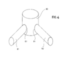
- FIG. 4 a part 8 can be seen which can be carried out by the process according to the invention.
- This piece 8 results from the radial assembly on a sleeve 80 of two bushes 81 and 82, by their portion, respectively 83 and 84.
Abstract
Description
La présente invention a pour objet un procédé de moulage d'une pièce en matériau composite et le dispositif permettant la mise en oeuvre dudit procédé.The present invention relates to a method of molding a part composite material and the device for carrying out said method.
On connaít déjà différents procédés de moulage de pièces en matériau composite, permettant de mettre en forme ledit matériau, qui consiste en des fibres noyées dans une matrice thermodurcissable ou thermoplastique, au moyen d'un moule et en association avec des conditions particulières de pression et de température.We already know different processes for molding parts made of material composite, for shaping said material, which consists of fibers embedded in a thermosetting matrix or thermoplastic, by means of a mold and in combination with special conditions of pressure and temperature.
Les fibres consistent généralement en du verre, du carbone ou de l'aramide, tandis que la matrice est du type époxyde, phénolique ou autre.Fibers usually consist of glass, carbon or aramid, while the matrix is epoxide, phenolic or other.
Les procédés connus diffèrent également selon la manière dont le matériau composite est mis en oeuvre dans le moule. Ces procédés utilisent pour la plupart un mat se présentant sous la forme d'une nappe non tissée de fibres s'étendant parallèlement, et dans laquelle sont prélevés soit des plis destinés à être superposés, en variant éventuellement l'orientation de fibres afin d'augmenter la résistance de l'ensemble, soit des morceaux plus ou moins longs et/ou larges que l'on dispose dans le moule, lesdits morceaux de nappe pré-imprégnée étant disposés en vrac de manière aléatoire ou selon un arrangement tridimensionnel particulier lié à l'usage de la pièce à réaliser.The known methods also differ depending on how the composite material is implemented in the mold. These methods use for the most part a mat in the form of a nonwoven web of fibers extending in parallel, and in which are taken either folds intended to be superimposed, in possibly varying the fiber orientation to increase the resistance of the set, ie longer or shorter pieces and / or wide that is available in the mold, said pieces of pre-impregnated sheet being randomly arranged in bulk or according to a particular three-dimensional arrangement related to the use of the piece to realize.
On notera que les morceaux de nappe pré-imprégnée peuvent être conformés en une structure réalisée en dehors du moule, ce qui permet d'arranger les fibres selon une orientation préférée, et ainsi obtenir une résistance accrue à un effort connu, cette manière de faire est toutefois coûteuse en temps. It should be noted that the pieces of pre-impregnated sheet can be shaped into a structure made outside the mold, which allows the fibers to be arranged in a preferred orientation, and thus get increased resistance to a known effort, this way to do is, however, expensive in time.
Le document EP 0.025.689 décrit un complexe réalisé par un tel procédé, et qui consiste en une feuille faite de l'assemblage de deux feuilles elles-mêmes constituées de l'assemblage de morceaux découpés dans une nappe de fibres pré-imprégnées.The document EP 0.025.689 describes a complex made by such a process, and which consists of a sheet made of the assembly of two leaves themselves made up of pieces cut into a sheet of pre-impregnated fibers.
On connaít également par le document FR 2.740.149 un procédé de moulage à partir d'une feuille constituée d'un assemblage de morceaux d'une nappe de fibres pré-imprégnées. Les morceaux de nappe sont superposés à plat et au hasard, pour former une structure qui est ensuite soumis à une pression de l'ordre de 10 à 80 kg/cm2 et à une température de l'ordre de 210 à 350°C.Also known from FR 2,740,149 a molding process from a sheet consisting of an assembly of pieces of a sheet of pre-impregnated fibers. The pieces of sheet are superimposed flat and randomly, to form a structure which is then subjected to a pressure of the order of 10 to 80 kg / cm 2 and a temperature of the order of 210 to 350 ° C.
D'autre part, le document EP 0.916.477 décrit un procédé de moulage d'une pièce en matériau composite à partir d'une structure composite constituée de l'assemblage de morceaux d'une nappe de fibres pré-imprégnées, où lesdits morceaux sont disposés de manière à obtenir un arrangement tridimensionnel des fibres, ladite structure étant ensuite soumise à température de l'ordre de 150°C et à une pression de l'ordre de 10 à 100 bars.On the other hand, the document EP 0.916.477 describes a molding process of a composite material part from a composite structure consisting of the assembly of pieces of a sheet of pre-impregnated fibers, where said pieces are arranged so as to obtain a three-dimensional arrangement of the fibers, said structure being then subjected to a temperature of the order of 150 ° C. and at a pressure of of the order of 10 to 100 bar.
On notera qu'il a été ainsi constaté, lors de la mise sous forte pression, un fluage de la matrice thermodurcissable ou thermoplastique, que l'on peut assimiler à un essorage des fibres en sorte que la pièce obtenue est d'une faible résistanceIt will be noted that it was thus noted, when placing under strong pressure, a creep of the thermosetting matrix or thermoplastic, which can be likened to spinning the fibers in so that the part obtained is of low resistance
Les procédés précités sont destinés à la fabrication d'objets particuliers, ainsi le procédé du document FR 2.740.149 est destiné à la fabrication d'embouts renforcés de chaussures, tandis que le procédé du document EP 0.916.477 est essentiellement destiné à la fabrication d'objets du type manivelles de pédalier de bicyclette. Si ces objets sont d'une grande résistance, celle-ci est toutefois limitée, ce qui ne permet pas la fabrication de certaines pièces qui présentent une certaine complexité de forme.The aforementioned methods are intended for the manufacture of objects particular, the method of document FR 2.740.149 is intended the manufacture of reinforced toe caps, while the The method of EP 0.916.477 is essentially intended for the making objects of the crank type crank bicycle. If these objects are of great resistance, it is nevertheless limited, which does not allow the manufacture of certain parts which have a certain complexity of form.
Dans le cas par exemple de pièces creuses présentant des éléments d'axes différents se rejoignant, il convient d'utiliser un noyau autour de chacune des parties duquel sont disposés des matelas de plis, puis de mettre l'ensemble dans un moule sous pression. Toutefois on peut constater une très mauvaise liaison entre eux des différents éléments, du fait que celle-ci résulte du fluage uniquement de la matrice thermodurcissable ou thermoplastique.In the case for example of hollow parts with elements of different axes joining together, a nucleus should be used around each of which are arranged mattresses of folds, then put the set in a mold under pressure. However we can see a very bad connection between them different elements, because it results from creep only thermosetting or thermoplastic matrix.
Par ailleurs, dans le cas particulier d'un objet présentant un ou plusieurs trous traversants, il est possible de procéder de différentes manièresMoreover, in the particular case of an object presenting one or several through holes, it is possible to proceed from different ways
On peut réaliser un perçage après moulage avec l'inconvénient, outre la difficulté de réalisation du fait de la dureté du matériau, du sectionnement de fibres ce qui crée une relative faiblesse aux abords du trou.Drilling after molding can be achieved with the disadvantage, besides the difficulty of realization because of the hardness of the material, the cutting of fibers which creates a relative weakness in around the hole.
On peut également comme cela est préconisé dans le document EP 0.916.477, utiliser un insert ou noyau disposé dans le moule, et, éventuellement, enrouler des morceaux de nappe de fibres pré-imprégnées autour de cet insert ou noyau, ce qui présente des risques de discontinuité du réseau de fibres sur l'ensemble de l'objet réalisé.One can also as is advocated in the document EP 0.916.477, use an insert or core disposed in the mold, and, possibly, winding pieces of pre-impregnated fiber web around this insert or core, which presents risks of discontinuity of the fiber network over the whole of the realized object.
Par ailleurs, les procédés actuellement connus nécessitent après démoulage des travaux d'usinage et d'ébavurage coûteux en main d'oeuvre, et qui peuvent nuire à la résistance de l'objet réalisé.Moreover, the currently known processes require after demolding expensive machining and deburring work in hand of work, and which may affect the resistance of the object.
On connaít également par le document EP 0 355 641, JP 02 131929 EP et 0 755 772, des procédés de fabrication d'objets en matériau composite par moulage où il est prévu de réaliser des étapes de mise en forme, d'élimination de surplus de matière, de pression et de chauffage puis de refroidissement. On a pu constater que les objets obtenus par les procédés décrits dans ces documents ne présentent pas une résistance homogène, du fait notamment desdits procédés et des dispositifs permettant leur mise en oeuvre. Also known from EP 0 355 641, JP 02 131929 EP and 0 755 772, methods of manufacturing objects of material molding composite where it is planned to carry out placing steps in form, disposal of excess material, pressure and heating then cooling. It has been found that the objects obtained by the processes described in these documents do not not a homogeneous resistance, in particular because of said methods and devices for their implementation.
La présente invention a pour but de remédier à ces divers inconvénients en proposant un procédé de moulage d'une pièce en matériau composite, qui permet notamment de réaliser des pièces d'une résistance supérieure à celle des pièces obtenues par les procédés de moulage actuellement connus, quelle que soit la complexité de cette pièce.The present invention aims to remedy these various disadvantages by proposing a method of molding a piece of composite material, which makes it possible to produce parts greater strength than the parts obtained by the molding processes currently known, regardless of the complexity of this piece.
Le procédé de moulage d'une pièce en matériau composite selon l'invention est du type consistant à placer dans un moule un empilement de plis prélevés dans une nappe de fibres noyées dans une matrice thermodurcissable ou thermoplastique, et arrangés selon des directions préférentielles desdites fibres, et à soumettre ledit moule à des conditions particulières de pression et de température, et il se caractérise en ce qu'il consiste à réaliser des opérations successives de:
- mise en forme dudit empilement de plis dans le moule, sous une pression faible réalisée progressivement à vitesse lente,
- élimination du surplus de matière sortant du bord du moule,
- réalisation de l'étanchéité du moule par l'extérieur,
- augmentation de la pression jusqu'à une forte pression,
- montée en température du moule,
- refroidissement rapide du moule.
- shaping said stack of folds in the mold, under a low pressure progressively achieved at slow speed,
- elimination of excess material leaving the edge of the mold,
- sealing of the mold from the outside,
- increase of the pressure until a strong pressure,
- temperature rise of the mold,
- rapid cooling of the mold.
Le procédé selon l'invention permet de réaliser un véritable forgeage du matériau composite, qui donne à la pièce obtenue une très grande résistance, ce qui permet d'envisager la fabrication de pièces jusque là réalisées en métal, de l'aluminium par exemple.The method according to the invention makes it possible to achieve a true forging of the composite material, which gives the piece obtained a very high strength, which makes it possible to envisage the manufacture of parts hitherto made of metal, aluminum for example.
Les procédés existants, notamment ceux décrits dans les documents EP 0 355 641, JP 02 131929 EP et 0 755 772, ne permettent pas d'atteindre ce résultat, en effet, l'enlèvement du surplus de matière est réalisé avant la mise en forme et avant la mise sous pression, en sorte que la quantité de matière utilisée n'est pas optimale, et la coupe en cours de pression engendre généralement un fluage de la matrice thermodurcissable, avec pour conséquence un affaiblissement de la pièce obtenue par moulage.Existing processes, including those described in EP documents 0 355 641, JP 02 131929 EP and 0 755 772, do not allow to achieve this result, indeed, the removal of the surplus of material is made before formatting and before pressure, so that the amount of material used is not optimal, and cutting during pressure usually generates a creep of the thermosetting matrix, with the consequent weakening of the part obtained by molding.
De plus, dans les procédés des documents précités, il n'est pas prévu de réaliser l'étanchéité du moule en sorte que l'on observe le fluage de la matrice thermodurcissable ou thermoplastique.Moreover, in the processes of the aforementioned documents, it is not planned to seal the mold so that we observe the creep of the thermosetting or thermoplastic matrix.
Selon une caractéristique additionnelle du procédé selon l'invention, la forte pression est comprise entre 50 et 200 bars, tandis que la température de chauffage du moule est comprise entre 125 et 135°C.According to an additional feature of the method according to the invention, the high pressure is between 50 and 200 bar, while the heating temperature of the mold is between 125 and 135 ° C.
On notera que l'utilisation d'une pression jusqu'à 200 bars n'est possible que du fait de la réalisation de l'étanchéité du moule par l'extérieur, dans le cas contraire on observe un essorage des fibres.It should be noted that the use of a pressure up to 200 bar is possible that due to the fact of the sealing of the mold by the outside, in the opposite case we observe a spin of fibers.
Selon une autre caractéristique additionnelle du procédé selon l'invention, l'opération d'élimination du surplus de matière est associée, si la pièce à réaliser doit comporter un ou plusieurs trous traversants, à une opération de poinçonnage au travers du moule.According to another additional feature of the method according to the invention, the surplus material removal operation is associated, if the part to be produced must include one or more through holes, to a punching operation through the mold.
Simultanément à l'enlèvement de la matière en surplus, on réalise un poinçonnage au travers du moule, et le ou les poinçons ou emporte-pièce sont maintenus en place durant les opérations de pression et de chauffage.Simultaneously with the removal of the surplus material, a punching through the mold, and punch (s) or punch are kept in place during pressure operations and of heating.
Lors de l'amorce du poinçonnage les fibres ne sont pas immédiatement coupées, en sorte qu'après découpe les extrémités de celles-ci sont orientées selon un autre axe que leur axe principal, ce qui donne au bord du trou une résistance particulière, ce que ne permet pas d'obtenir, par exemple, une opération de perçage démoulage.When starting the punching the fibers are not immediately cut, so that after cutting the ends of these are oriented along an axis other than their main axis, which gives the edge of the hole a particular resistance, which does not allow to obtain, for example, a demolding drilling operation.
On notera qu'une la réorientation des extrémités des fibres est également obtenue sur le pourtour de la pièce lors de la coupe du surplus de matière.It will be noted that the reorientation of the ends of the fibers is also obtained around the edge of the room when cutting the surplus of material.
On notera que le poinçonnage est réalisé après mise en forme dans le moule sous une pression faible, ce qui revêt une grande importance. En effet dans le document EP 0 355 641 par exemple, on réalise un poinçonnage dans le moule avant mise en forme et avant mise sous pression, ou alors de manière simultanée et non successive, ce qui a pour conséquence un risque de fluage de la matrice thermodurcissable et également de suppression de certaines fibres, et donc la non obtention d'un forgeage.It will be noted that the punching is carried out after shaping in the mold under a low pressure, which is of great importance. Indeed in the document EP 0 355 641 for example, a punching in the mold before formatting and before putting pressure, or else simultaneously and not in succession, which has as a consequence a risk of creep of the thermosetting matrix and also suppressing certain fibers, and therefore the non obtaining a forging.
Pour la réalisation de pièces complexes telles que celles évoquées plus haut, c'est-à-dire, par exemple, creuse et comprenant plusieurs élément d'axes différents se rejoignant, la mise sous pression avec étanchéité du moule permet, puisqu'il n'y à pas essorage, de faire fluer les fibres en sorte d'obtenir un entrelacement des fibres d'un matelas destiné à la réalisation de l'un desdits éléments avec les fibres d'un ou de plusieurs autres matelas, pour aboutir à une pièce de grande résistance.For the realization of complex parts such as those evoked above, that is to say, for example, dig and including several element of different axes coming together, pressurizing with sealing of the mold allows, since there is no spin, to make flow the fibers so as to obtain an interlacing of the fibers of a mattress for producing one of said elements with the fibers of one or more other mattresses, to result in a piece of great resistance.
Le dispositif permettant la mise en oeuvre du procédé de moulage selon l'invention est du type comportant un moyen de pression d'un moule constitué d'au moins deux parties entre lesquelles est disposé l'empilement de plis, et il se caractérise essentiellement en ce qu'il comporte :
- un moyen de coupe mobile par rapport audit moule, et apte, sous l'action d'un moyen d'entraínement, à découper le surplus de matière débordant desdites parties après pressage de celles-ci et à épouser la forme externe desdites parties au niveau de leur ligne de jonction afin de constituer un joint étanche,
- ainsi que des moyens aptes à chauffer et à refroidir rapidement lesdites parties.
- a cutting means movable relative to said mold, and adapted, under the action of a drive means, to cut the excess material overflowing said parts after pressing thereof and to marry the external shape of said parts at the level of their junction line to form a tight seal,
- as well as means capable of rapidly heating and cooling said parts.
Les dispositifs existants sont prévus aptes à la mise en oeuvre des procédés existants, ainsi, ils comportent généralement deux parties entre lesquelles est disposé l'empilement de plis, lesdites parties présentant la forme à réaliser, et au moins l'une desdites parties comprend une lame de coupe ou analogue permettant d'éliminer le surplus de matière avant ou simultanément à la mise en forme, avec les inconvénients précités que cela génère.Existing devices are foreseen suitable for the implementation of the existing processes, as well, they usually involve two parts between which is arranged the stack of folds, said parts presenting the shape to be produced, and at least one of said parts comprises a cutting blade or the like for removing the surplus material before or at the same time as formatting, with the aforementioned drawbacks that this generates.
Selon une caractéristique additionnelle du dispositif selon l'invention, les moyens de pression et d'entraínement, consistent en des vérins alignés et agissant en sens opposés.According to an additional feature of the device according to the invention, the means of pressure and training, consist of cylinders aligned and acting in opposite directions.
Selon une autre caractéristique additionnelle du dispositif selon l'invention, les moyens aptes à chauffer et à refroidir rapidement les parties du moule consistent en des moyens permettant de faire circuler dans ceux-ci un liquide caloporteur pressurisé, associés à des moyens permettant de chauffer ou de refroidir ledit liquide caloporteur.According to another additional feature of the device according to the invention, the means capable of heating and cooling rapidly the mold parts consist of means to make circulating in these a pressurized heat transfer liquid, associated with means for heating or cooling said liquid coolant.
On notera que l'opération de chauffe peut être également réalisée électriquement ou par induction, le refroidissement demeurant au moyen d'un fluide caloporteur.It will be noted that the heating operation can also be performed electrically or by induction, the cooling remaining at medium of a coolant.
Selon une autre caractéristique additionnelle du dispositif selon l'invention, il comporte au moins un poinçon apte à traverser les parties du moule qui présentent à cet effet des trous en regard.According to another additional feature of the device according to the invention, it comprises at least one punch able to cross the parts of the mold which have holes for this purpose opposite.
Selon une autre caractéristique additionnelle du dispositif selon l'invention, le ou les poinçons sont solidaires des moyens de coupe et animés par le même moyen d'entraínement.According to another additional feature of the device according to the invention, the punch or punches are integral with the cutting means and animated by the same means of training.
Les avantages et les caractéristiques du dispositif selon l'invention, ressortiront plus clairement de la description qui suit et qui se rapporte au dessin annexé, lequel en représente un mode de réalisation non limitatif.The advantages and characteristics of the device according to invention, will emerge more clearly from the description which follows and which refers to the attached drawing, which represents a mode of non-limiting embodiment.
Dans le dessin annexé :
- les figures 1a, 1b, 1c et 1d représentent des vues schématiques illustrant différentes étapes du procédé de moulage selon l'invention.
- la figure 2 représente une vue en perspective d'une pièce réalisée par le procédé selon l'invention.
- la figure 3 représente une vue schématique en plan d'une partie du dispositif permettant la fabrication de la même pièce.
- la figure 4 représente une vue schématique en perspective d'un objet susceptible d'être réalisé par le procédé selon l'invention.
- Figures 1a, 1b, 1c and 1d show schematic views illustrating different steps of the molding process according to the invention.
- FIG. 2 represents a perspective view of a part made by the method according to the invention.
- Figure 3 shows a schematic plan view of a part of the device for the manufacture of the same part.
- FIG. 4 represents a schematic perspective view of an object that can be produced by the method according to the invention.
En référence à la figure 1a, on peut voir une première étape du
procédé de moulage selon l'invention, au moyen d'un dispositif
comprenant notamment un moule 1 réalisé en deux parties, une partie
mâle 10 et une partie femelle 11.With reference to FIG. 1a, we can see a first step of
molding method according to the invention, by means of a device
including a mold 1 made in two parts, a
La première étape consiste à disposer entre les deux parties 10 et
11 du moule 1, un empilement 2 de plis 20 découpés dans une nappe
fibres noyées dans une matrice thermodurcissable ou thermoplastique.
Les fibres consistent en du verre, du carbone ou de l'aramide,
tandis que la matrice est du type époxyde, phénolique ou autre. Les
plis 20 ne sont pas empilés au hasard, ils sont de préférence
arrangés en sorte que d'un pli 20 à l'autre les fibres s'étendent
dans des directions différentes de manière à réaliser un
entrecroisement prédéterminé.The first step is to arrange between the two
On notera que l'empilement 2 peut être soit disposé entre les
parties 10 et 11 du moule 1, soit appliqué sur l'une ou l'autre des
parties 10 et 11, afin d'éviter, dans le cas de d'une forme
particulièrement complexe de l'empreinte, un fluage de la matrice
thermodurcissable ou thermoplastique, et donc la création d'une ou
de plusieurs zones dépourvues de fibres de renfort.Note that the
L'étape suivante consiste à rapprocher les deux parties 10 et 11 et
à serrer l'empilement 2 sous une faible force le rapprochement des
parties 10 et 11 étant réalisé progressivement, à une vitesse de
l'ordre de 3 millimètres par seconde, en sorte que l'empilement
prenne la forme de l'empreinte comme cela est représenté sur la
figure 1b.The next step is to bring the two
La vitesse de rapprochement des deux parties 10 et 11 peut varier en
fonction de la complexité de la pièce à réaliser. De même, cette
vitesse peut varier en fonction de la température de l'outillage.
Une vitesse lente associée à une certaine température permettra plus
ou moins, selon le type de pièce, un glissement entre chaque pli.The speed of approach of the two
Les dimensions des plis 20 sont calculées en sorte qu'après mise en
forme ceux-ci débordent sur tout le pourtour du moule 1, afin
d'éviter la formation de manques. Il est donc nécessaire de procéder
à l'enlèvement du surplus 21, ce qui est réalisé au moyen d'un
couteau 3, mobile en translation verticale, et apte à épouser
intimement la forme extérieure du moule 1.The dimensions of the
On notera que le couteau 3 doit être de conception robuste, et que
d'autre part son fil 30 doit de préférence ne pas être contenu dans
un plan afin d'éviter, si le bord périphérique de la pièce à mouler
est en majorité plan, d'attaquer la matière parallèlement à celle-ci.
Ainsi, le fil 30 du couteau 3 décrit une ligne brisée ou une
courbe en sorte de ne jamais être parallèle avec la matière à
couper.Note that the
En référence à la figure 1c on peut voir que le couteau 3 a éliminé
le surplus de matière 21 et qu'il reste en place sur le pourtour du
moule 1, ce qui permet de fermer ce dernier de manière étanche. With reference to FIG. 1c, it can be seen that
Dans l'exemple représenté, la pièce 4 à réaliser doit comporter un
trou traversant 40 disposé centralement, aussi les parties 10 et 11
du moule 1 comportent chacune un orifice, respectivement 12 et 13,
tandis qu'un emporte-pièce 5, mobile en translation verticale, est
apte à être introduit dans l'orifice 12 puis dans l'orifice 13, en
sorte de réaliser le percement de l'empilement 2.In the example shown, the part 4 to be produced must comprise a
through
En référence maintenant à la figure 1d, on peut voir qu'après la
réalisation du percement de l'empilement 2, l'emporte-pièce 5 est
maintenu en place, de manière étanche, et les parties 10 et 11 sont
pressées l'une en direction de l'autre, ce qui est réalisé sous une
pression de l'ordre de 50 à 200 bars, tandis que simultanément elles
sont chauffées à une température de l'ordre de 125 à 135°C, de
préférence 132°C, la pression et la température étant maintenues
pendant une durée de l'ordre de 15 à 20 minutes.Referring now to Figure 1d, it can be seen that after the
making the piercing of the
On notera que de préférence il n'est pas prévu de butées de fin de
course sur les parties 10 et 11, la fermeture de celles-ci est
réalisée directement sur les plis 20, ce qui permet d'atteindre de
fortes pressions et nécessite, de ce fait, que l'étanchéité soit
parfaite pour éviter un essorage des fibres.It should be noted that preferably no end stops are provided.
La mise en température du moule 1 est réalisée au moyen d'un fluide caloporteur tel que de l'eau, circulant sous pression dans des canalisations, non représentées, que comporte chacune des parties 10 et 11, ou bien électriquement ou par induction.The temperature of the mold 1 is produced by means of a fluid coolant such as water, circulating under pressure in pipelines, not shown, that each of the parties has and 11, either electrically or by induction.
Le moule 1 est ensuite refroidi par l'intermédiaire d'un fluide
caloporteur, puis le couteau 3 ainsi que l'emporte-pièce 5 sont
enlevés, et les parties 10 et 11 du moule 1 sont séparées afin de
libérer la pièce moulée 4.The mold 1 is then cooled by means of a fluid
coolant, then the
Du point de vue mise en oeuvre, un vérin permet de presser les
parties 10 et 11 du moule 1 l'une contre l'autre, tandis qu'un
deuxième vérin, agissant dans le sens opposé au premier, pousse le
couteau 3 et qu'un troisième vérin d'action identique au deuxième
pousse l'emporte-pièce 5.From the point of view implemented, a cylinder makes it possible to press the
On notera que selon une variante, le couteau 3 et l'emporte-pièce 5
peuvent être solidaires, en sorte d'être mus par le même vérin, la
coupe et le poinçonnage étant ainsi réalisés simultanément.It will be noted that according to one variant, the
La pièce 4 ainsi réalisée est d'une très grande résistance, laquelle
n'est pas entamée par la présence du trou 40, puisqu'en effet la
réalisation de celui-ci n'altère pas la continuité du réseau de
fibres au niveau de l'ensemble de la pièce.The piece 4 thus produced is of a very great resistance, which
is not affected by the presence of
Par ailleurs, la réalisation du trou 40 pouvant être assimilée à un
forgeage autour de l'emporte-pièce 5, cela confère à la paroi qui le
borde une résistance inégalée par les procédés connus et qui
consistent soit à percer après démoulage, soit à placer dans le
moule un insert enrobé préalablement au moulage.Moreover, the realization of the
Le procédé de moulage selon l'invention peut présenter certaines
variantes, on peut ainsi utiliser un ou plusieurs inserts destinés à
prendre place dans l'empilement 2, ce ou ces inserts étant bien
entendu aptes à être calés dans le moule 1.The molding process according to the invention may have certain
variants, one can thus use one or more inserts for
take place in the
En référence maintenant à la figure 2, on peut voir une pièce réalisée par le procédé selon l'invention. Il s'agit d'une demi-coque 6 d'un moyeu pour hélices d'un ultralégermotorisé (ULM), sachant deux demi-coques identiques permettent de réaliser un moyeu.Referring now to Figure 2, a part can be seen performed by the method according to the invention. This is a half-hull 6 of a hub for propellers of an ultralégermotorisé (ULM), knowing two identical half-shells make it possible to make a hub.
Comme on peut le voir, cette demi-coque 6 présente dans sa région
médiane une partie creuse 60 dans laquelle débouchent deux parties
61 de forme semi-tubulaire destinées chacune au passage de
l'extrémité d'une pale, tandis que le pourtour 62 est en majorité
plan.As can be seen, this half-shell 6 has in its region
median a
On peut constater que la demi-coque 6 comporte de nombreux orifices
63, 64 et 65 respectivement de centrage de l'hélice, de fixation du
plateau et de blocage des pales, tous réalisés par le procédé selon
l'invention au moyen d'un mandrin comportant autant d'emporte-pièce.It can be seen that the half-shell 6 has
En référence maintenant à la figure 3, on peut voir la partie 7,
mâle ou femelle, d'un moule permettant de fabriquer une demi-coque
6. On peut constater que cette partie 7 comporte des trous 70
destinés au passage des emporte-pièce, ainsi qu'un canal interne
périphérique 71 présentant une entrée 72 et une sortie 73, et
destiné à la circulation d'un fluide caloporteur tel que de l'eau,
permettant de réaliser la montée en température du moule, et
notamment le refroidissement rapide de celui-ci.Referring now to Figure 3, we can see
En référence maintenant à la figure 4, on peut voir une pièce 8
susceptible d'être réalisée par le procédé selon l'invention. Cette
pièce 8 résulte de l'assemblage radial sur une douille 80 de deux
douilles 81 et 82, par leur tranche, respectivement 83 et 84.Referring now to FIG. 4, a part 8 can be seen
which can be carried out by the process according to the invention. This
piece 8 results from the radial assembly on a
En pratique, on utilise un noyau sur lequel sont disposés des
empilements de plis pour la réalisation d'un manchon pour chacune
des douilles 80, 81 et 82, en association avec des plis de liaison
recouvrant ces manchons. Avec les procédés existants, la
solidarisation des douilles 80, 81 et 82 tient uniquement aux plis
de liaison, et au fluage de la matrice thermodurcissable en sorte
que l'on obtient une pièce de faible résistance.In practice, a nucleus on which
stacks of folds for making a sleeve for each
Avec le procédé selon l'invention, on observe, du fait notamment de
l'association étanchéité - forte pression, un fluage des fibres ce
qui augmente considérablement la liaison entre les douilles.
Le procédé selon l'invention permet ainsi de réaliser
industriellement des pièces complexes.With the method according to the invention, due in particular to the combination sealing - high pressure, a creep fibers which significantly increases the connection between the sleeves.
The method according to the invention thus makes it possible to industrially produce complex parts.
Claims (9)
Priority Applications (7)
| Application Number | Priority Date | Filing Date | Title |
|---|---|---|---|
| FR0101484A FR2820359B1 (en) | 2002-07-19 | 2001-02-05 | PROCESS AND DEVICE FOR MOLDING A PART IN COMPOSITE MATERIAL, AND ULM PROPELLER HUB WHICH THEY ALLOW THEM TO MAKE |
| EP02360217A EP1382436B1 (en) | 2002-07-19 | 2002-07-19 | Method for moulding a composite article and moulding apparatus for carrying out said method |
| DE60216438T DE60216438T2 (en) | 2002-07-19 | 2002-07-19 | A method of molding a composite article and apparatus for carrying out this method |
| AT02360217T ATE346740T1 (en) | 2002-07-19 | 2002-07-19 | METHOD FOR SHAPING A COMPOSITE ARTICLE AND APPARATUS FOR PERFORMING SUCH METHOD |
| ES02360217T ES2277996T3 (en) | 2002-07-19 | 2002-07-19 | MOLDING PROCESS OF A COMPOSITE MATERIAL PART AND DEVICE THAT ALLOWS THE IMPLEMENTATION OF THIS PROCESS. |
| TW091117454A TW565501B (en) | 2002-07-19 | 2002-08-02 | Process for moulding a part made out of a composite material and device allowing implementing said process |
| CA002397188A CA2397188C (en) | 2002-07-19 | 2002-08-07 | Procedure for moulding a part made of a composite material and a device for implementing the said procedure |
Applications Claiming Priority (1)
| Application Number | Priority Date | Filing Date | Title |
|---|---|---|---|
| EP02360217A EP1382436B1 (en) | 2002-07-19 | 2002-07-19 | Method for moulding a composite article and moulding apparatus for carrying out said method |
Publications (2)
| Publication Number | Publication Date |
|---|---|
| EP1382436A1 true EP1382436A1 (en) | 2004-01-21 |
| EP1382436B1 EP1382436B1 (en) | 2006-11-29 |
Family
ID=37517967
Family Applications (1)
| Application Number | Title | Priority Date | Filing Date |
|---|---|---|---|
| EP02360217A Expired - Lifetime EP1382436B1 (en) | 2002-07-19 | 2002-07-19 | Method for moulding a composite article and moulding apparatus for carrying out said method |
Country Status (7)
| Country | Link |
|---|---|
| EP (1) | EP1382436B1 (en) |
| AT (1) | ATE346740T1 (en) |
| CA (1) | CA2397188C (en) |
| DE (1) | DE60216438T2 (en) |
| ES (1) | ES2277996T3 (en) |
| FR (1) | FR2820359B1 (en) |
| TW (1) | TW565501B (en) |
Cited By (7)
| Publication number | Priority date | Publication date | Assignee | Title |
|---|---|---|---|---|
| FR2830482A1 (en) * | 2001-10-04 | 2003-04-11 | Eads Deutschland Gmbh | Carbon fibre reinforced structure has force transmission elements in shape of tubes connected to structure by flanges between layers |
| EP2134533A2 (en) * | 2007-03-29 | 2009-12-23 | Carbone Forge | Method for making a thermoplastic composite part by moulding |
| EP2218566A1 (en) | 2009-02-13 | 2010-08-18 | Carbone Forge S.A.S. | Method for manufacturing a composite part with a hollow monolithic structure by moulding under pressure |
| CN103496173A (en) * | 2013-09-11 | 2014-01-08 | 重庆大学 | Manufacturing method of composite material laminated plate with holes |
| WO2014182429A1 (en) * | 2013-05-06 | 2014-11-13 | Dow Global Technologies Llc | Forming tool with integral cutting for composite materials |
| JP2019006105A (en) * | 2017-04-07 | 2019-01-17 | ゼネラル・エレクトリック・カンパニイ | Method and assembly for formation of fixture in composite material part |
| CN111746004A (en) * | 2020-07-15 | 2020-10-09 | 赵淑英 | Pressing mechanism with demolding and trimming mechanism for industrial composite material processing |
Families Citing this family (12)
| Publication number | Priority date | Publication date | Assignee | Title |
|---|---|---|---|---|
| FR2841818B1 (en) * | 2002-07-02 | 2005-05-06 | Inoplast Sa | METHOD, MOLD AND DEVICE FOR MANUFACTURING A COMPOSITE MOLDED PERFORATED PIECE |
| DE102008033621A1 (en) * | 2008-07-17 | 2010-01-21 | Volkswagen Ag | Plastic component for motor vehicles, comprises a reinforcing insert embedded in the component, where the reinforcing insert is formed by separate, pre-fabricated and preformed fabric inserts and/or mats made of aligned endless fibers |
| EP3225384B1 (en) * | 2010-08-31 | 2021-11-10 | Campagnolo S.R.L. | Bicycle wheel rim |
| CN102173060B (en) * | 2011-02-24 | 2014-04-09 | 江苏大学 | Device and method for manufacturing carbon fiber reinforced composite construction member |
| DE102011101954A1 (en) * | 2011-05-18 | 2012-11-22 | Claas Fertigungstechnik Gmbh | Method for producing a substantially cup-shaped plastic part |
| FR2980733B1 (en) * | 2011-10-03 | 2014-06-20 | Daher Aerospace | METHOD FOR PRODUCING A FALLED EDGE HOLE IN A COMPOSITE PANEL AND PANEL OBTAINED BY SUCH A METHOD |
| US10960612B2 (en) | 2015-07-08 | 2021-03-30 | Mitsubishi Chemical Corporation | Method for manufacturing fiber-reinforced composite material and fiber-reinforced composite material |
| WO2018080906A1 (en) * | 2016-10-24 | 2018-05-03 | Dow Global Technologies Llc | Forming and cutting tool for composite material |
| US10502074B2 (en) | 2017-04-07 | 2019-12-10 | General Electric Company | Methods and assemblies for forming features in composite components |
| US10632650B2 (en) | 2017-04-07 | 2020-04-28 | General Electric Company | Methods and assemblies for forming features in composite components |
| DE102018126624A1 (en) * | 2017-10-26 | 2019-05-02 | Faurecia Automotive Composites | Method for producing a workpiece made of composite material |
| DE102018112174A1 (en) * | 2018-05-22 | 2019-11-28 | Airbus Operations Gmbh | Apparatus and method for producing a composite component |
Citations (3)
| Publication number | Priority date | Publication date | Assignee | Title |
|---|---|---|---|---|
| EP0355641A2 (en) * | 1988-08-24 | 1990-02-28 | Manville Corporation | Laminating tool and method |
| JPH02131929A (en) * | 1988-11-14 | 1990-05-21 | Sekisui Chem Co Ltd | Method and apparatus for manufacturing fiber reinforced plastic(frp) formed item |
| EP0755772A1 (en) * | 1995-07-27 | 1997-01-29 | Sumitomo Chemical Company Limited | Mold assembly and method for producing fiber-reinforced thermoplastic resin molded article laminated with skin material |
-
2001
- 2001-02-05 FR FR0101484A patent/FR2820359B1/en not_active Expired - Lifetime
-
2002
- 2002-07-19 DE DE60216438T patent/DE60216438T2/en not_active Expired - Lifetime
- 2002-07-19 EP EP02360217A patent/EP1382436B1/en not_active Expired - Lifetime
- 2002-07-19 AT AT02360217T patent/ATE346740T1/en not_active IP Right Cessation
- 2002-07-19 ES ES02360217T patent/ES2277996T3/en not_active Expired - Lifetime
- 2002-08-02 TW TW091117454A patent/TW565501B/en not_active IP Right Cessation
- 2002-08-07 CA CA002397188A patent/CA2397188C/en not_active Expired - Lifetime
Patent Citations (3)
| Publication number | Priority date | Publication date | Assignee | Title |
|---|---|---|---|---|
| EP0355641A2 (en) * | 1988-08-24 | 1990-02-28 | Manville Corporation | Laminating tool and method |
| JPH02131929A (en) * | 1988-11-14 | 1990-05-21 | Sekisui Chem Co Ltd | Method and apparatus for manufacturing fiber reinforced plastic(frp) formed item |
| EP0755772A1 (en) * | 1995-07-27 | 1997-01-29 | Sumitomo Chemical Company Limited | Mold assembly and method for producing fiber-reinforced thermoplastic resin molded article laminated with skin material |
Non-Patent Citations (1)
| Title |
|---|
| PATENT ABSTRACTS OF JAPAN vol. 014, no. 367 (M - 1008) 9 August 1990 (1990-08-09) * |
Cited By (7)
| Publication number | Priority date | Publication date | Assignee | Title |
|---|---|---|---|---|
| FR2830482A1 (en) * | 2001-10-04 | 2003-04-11 | Eads Deutschland Gmbh | Carbon fibre reinforced structure has force transmission elements in shape of tubes connected to structure by flanges between layers |
| EP2134533A2 (en) * | 2007-03-29 | 2009-12-23 | Carbone Forge | Method for making a thermoplastic composite part by moulding |
| EP2218566A1 (en) | 2009-02-13 | 2010-08-18 | Carbone Forge S.A.S. | Method for manufacturing a composite part with a hollow monolithic structure by moulding under pressure |
| WO2014182429A1 (en) * | 2013-05-06 | 2014-11-13 | Dow Global Technologies Llc | Forming tool with integral cutting for composite materials |
| CN103496173A (en) * | 2013-09-11 | 2014-01-08 | 重庆大学 | Manufacturing method of composite material laminated plate with holes |
| JP2019006105A (en) * | 2017-04-07 | 2019-01-17 | ゼネラル・エレクトリック・カンパニイ | Method and assembly for formation of fixture in composite material part |
| CN111746004A (en) * | 2020-07-15 | 2020-10-09 | 赵淑英 | Pressing mechanism with demolding and trimming mechanism for industrial composite material processing |
Also Published As
| Publication number | Publication date |
|---|---|
| CA2397188C (en) | 2007-03-27 |
| FR2820359B1 (en) | 2003-10-24 |
| TW565501B (en) | 2003-12-11 |
| DE60216438D1 (en) | 2007-01-11 |
| ES2277996T3 (en) | 2007-08-01 |
| FR2820359A1 (en) | 2002-08-09 |
| CA2397188A1 (en) | 2004-02-07 |
| DE60216438T2 (en) | 2007-09-27 |
| ATE346740T1 (en) | 2006-12-15 |
| EP1382436B1 (en) | 2006-11-29 |
Similar Documents
| Publication | Publication Date | Title |
|---|---|---|
| EP1382436B1 (en) | Method for moulding a composite article and moulding apparatus for carrying out said method | |
| EP0916477B1 (en) | Method for moulding a composite object, and composite structure used in said process | |
| EP0984853B1 (en) | Equipment for on-site repair of a composite structure with a damaged zone and corresponding method | |
| EP0581098B1 (en) | Procedure for manufacturing of a ski | |
| EP1136239B1 (en) | Method for producing a reinforced thermoplastic part and mould | |
| EP2640566B1 (en) | Process for manufacturing a spring made of a composite material, such as a suspension spring in particular for a motor vehicle | |
| EP2252453B1 (en) | Method and device for perforating a thermoplastic composite | |
| EP0042782A1 (en) | Protective helmet with a shell made of injection moulded thermoplastic material, and method of manufacturing said helmet | |
| FR2760681A1 (en) | PROCESS FOR THE MANUFACTURE OF A LARGE-DIMENSIONAL PART OF COMPOSITE MATERIAL AND PROPELLER BLADE, PARTICULARLY A WIND TURBINE, MANUFACTURED ACCORDING TO THIS PROCESS | |
| FR2806346A1 (en) | Manufacture of spare wheel compartment for vehicles, etc. by adding thermoplastic onto thermoplastic sandwich in female mold part and fusing together to form article with thermoplastic interior part | |
| FR2956057A1 (en) | CUTTING PREFORMS BEFORE INJECTION RTM BY WATER JET AND CRYOGENIZATION | |
| EP0770472A1 (en) | Process for manufacturing a panel in a composite material by resin transfer moulding | |
| FR2999970A1 (en) | METHOD OF MAKING A CONTINUOUS FIBER TEXTILE PREFORM BY CIRCULATING A HOT GAS FLOW THROUGH A FIBROUS ASSEMBLY | |
| FR3026980A1 (en) | METHOD FOR IMMOBILIZING A PREFORM IN A MOLD | |
| WO1992010244A1 (en) | Method for fabricating golf club shafts | |
| FR2877256A1 (en) | PROCESS FOR THE MANUFACTURE OF A FUEL TANK OF PLASTIC MATERIAL COMPRISING AN INTEGRATED CHUTE | |
| WO2003078126A2 (en) | Method of producing a compression-moulded plastic part comprising a neck which is equipped with a dispensing orifice | |
| FR2763881A1 (en) | Piercing of composite fibre panel damage during hole formation for fastenings | |
| WO2020234313A1 (en) | Device and method for manufacturing a part from a composite material | |
| EP3053734B1 (en) | Method for manufacturing parts in composite material | |
| WO2014020292A1 (en) | Method for producing a mould intended for moulding a composite part | |
| EP2845707A1 (en) | Provisional maintaining of a strap on an RTM mould by microwelds | |
| FR2613662A2 (en) | PROCESS FOR REALIZING THE COMPOSITE MATERIALS BY PACKING AND DEVICE FOR IMPLEMENTING THE SAME | |
| FR3053622A1 (en) | PROCESS FOR MANUFACTURING A PIECE OF COMPOSITE MATERIAL, AND LINK MANUFACTURED ACCORDING TO SAID METHOD | |
| EP2146834B1 (en) | Method and device for compression moulding composite materials |
Legal Events
| Date | Code | Title | Description |
|---|---|---|---|
| PUAI | Public reference made under article 153(3) epc to a published international application that has entered the european phase |
Free format text: ORIGINAL CODE: 0009012 |
|
| AK | Designated contracting states |
Kind code of ref document: A1 Designated state(s): AT BE BG CH CY CZ DE DK EE ES FI FR GB GR IE IT LI LU MC NL PT SE SK TR |
|
| AX | Request for extension of the european patent |
Extension state: AL LT LV MK RO SI |
|
| 17P | Request for examination filed |
Effective date: 20040719 |
|
| AKX | Designation fees paid |
Designated state(s): AT BE BG CH CY CZ DE DK EE ES FI FR GB GR IE IT LI LU MC NL PT SE SK TR |
|
| AXX | Extension fees paid |
Extension state: RO Payment date: 20040719 |
|
| GRAP | Despatch of communication of intention to grant a patent |
Free format text: ORIGINAL CODE: EPIDOSNIGR1 |
|
| GRAS | Grant fee paid |
Free format text: ORIGINAL CODE: EPIDOSNIGR3 |
|
| GRAA | (expected) grant |
Free format text: ORIGINAL CODE: 0009210 |
|
| AK | Designated contracting states |
Kind code of ref document: B1 Designated state(s): AT BE BG CH CY CZ DE DK EE ES FI FR GB GR IE IT LI LU MC NL PT SE SK TR |
|
| AX | Request for extension of the european patent |
Extension state: RO |
|
| PG25 | Lapsed in a contracting state [announced via postgrant information from national office to epo] |
Ref country code: IE Free format text: LAPSE BECAUSE OF FAILURE TO SUBMIT A TRANSLATION OF THE DESCRIPTION OR TO PAY THE FEE WITHIN THE PRESCRIBED TIME-LIMIT Effective date: 20061129 Ref country code: FI Free format text: LAPSE BECAUSE OF FAILURE TO SUBMIT A TRANSLATION OF THE DESCRIPTION OR TO PAY THE FEE WITHIN THE PRESCRIBED TIME-LIMIT Effective date: 20061129 Ref country code: CZ Free format text: LAPSE BECAUSE OF FAILURE TO SUBMIT A TRANSLATION OF THE DESCRIPTION OR TO PAY THE FEE WITHIN THE PRESCRIBED TIME-LIMIT Effective date: 20061129 Ref country code: NL Free format text: LAPSE BECAUSE OF FAILURE TO SUBMIT A TRANSLATION OF THE DESCRIPTION OR TO PAY THE FEE WITHIN THE PRESCRIBED TIME-LIMIT Effective date: 20061129 Ref country code: SK Free format text: LAPSE BECAUSE OF FAILURE TO SUBMIT A TRANSLATION OF THE DESCRIPTION OR TO PAY THE FEE WITHIN THE PRESCRIBED TIME-LIMIT Effective date: 20061129 Ref country code: AT Free format text: LAPSE BECAUSE OF FAILURE TO SUBMIT A TRANSLATION OF THE DESCRIPTION OR TO PAY THE FEE WITHIN THE PRESCRIBED TIME-LIMIT Effective date: 20061129 |
|
| REG | Reference to a national code |
Ref country code: GB Ref legal event code: FG4D Free format text: NOT ENGLISH |
|
| REG | Reference to a national code |
Ref country code: CH Ref legal event code: EP |
|
| REG | Reference to a national code |
Ref country code: IE Ref legal event code: FG4D Free format text: LANGUAGE OF EP DOCUMENT: FRENCH |
|
| REF | Corresponds to: |
Ref document number: 60216438 Country of ref document: DE Date of ref document: 20070111 Kind code of ref document: P |
|
| PG25 | Lapsed in a contracting state [announced via postgrant information from national office to epo] |
Ref country code: SE Free format text: LAPSE BECAUSE OF FAILURE TO SUBMIT A TRANSLATION OF THE DESCRIPTION OR TO PAY THE FEE WITHIN THE PRESCRIBED TIME-LIMIT Effective date: 20070228 Ref country code: BG Free format text: LAPSE BECAUSE OF FAILURE TO SUBMIT A TRANSLATION OF THE DESCRIPTION OR TO PAY THE FEE WITHIN THE PRESCRIBED TIME-LIMIT Effective date: 20070228 Ref country code: DK Free format text: LAPSE BECAUSE OF FAILURE TO SUBMIT A TRANSLATION OF THE DESCRIPTION OR TO PAY THE FEE WITHIN THE PRESCRIBED TIME-LIMIT Effective date: 20070228 |
|
| GBT | Gb: translation of ep patent filed (gb section 77(6)(a)/1977) |
Effective date: 20070314 |
|
| PG25 | Lapsed in a contracting state [announced via postgrant information from national office to epo] |
Ref country code: PT Free format text: LAPSE BECAUSE OF FAILURE TO SUBMIT A TRANSLATION OF THE DESCRIPTION OR TO PAY THE FEE WITHIN THE PRESCRIBED TIME-LIMIT Effective date: 20070430 |
|
| NLV1 | Nl: lapsed or annulled due to failure to fulfill the requirements of art. 29p and 29m of the patents act | ||
| REG | Reference to a national code |
Ref country code: IE Ref legal event code: FD4D |
|
| REG | Reference to a national code |
Ref country code: ES Ref legal event code: FG2A Ref document number: 2277996 Country of ref document: ES Kind code of ref document: T3 |
|
| PLBE | No opposition filed within time limit |
Free format text: ORIGINAL CODE: 0009261 |
|
| STAA | Information on the status of an ep patent application or granted ep patent |
Free format text: STATUS: NO OPPOSITION FILED WITHIN TIME LIMIT |
|
| 26N | No opposition filed |
Effective date: 20070830 |
|
| PG25 | Lapsed in a contracting state [announced via postgrant information from national office to epo] |
Ref country code: GR Free format text: LAPSE BECAUSE OF FAILURE TO SUBMIT A TRANSLATION OF THE DESCRIPTION OR TO PAY THE FEE WITHIN THE PRESCRIBED TIME-LIMIT Effective date: 20070301 |
|
| PG25 | Lapsed in a contracting state [announced via postgrant information from national office to epo] |
Ref country code: EE Free format text: LAPSE BECAUSE OF FAILURE TO SUBMIT A TRANSLATION OF THE DESCRIPTION OR TO PAY THE FEE WITHIN THE PRESCRIBED TIME-LIMIT Effective date: 20061129 |
|
| PG25 | Lapsed in a contracting state [announced via postgrant information from national office to epo] |
Ref country code: CY Free format text: LAPSE BECAUSE OF FAILURE TO SUBMIT A TRANSLATION OF THE DESCRIPTION OR TO PAY THE FEE WITHIN THE PRESCRIBED TIME-LIMIT Effective date: 20061129 |
|
| PG25 | Lapsed in a contracting state [announced via postgrant information from national office to epo] |
Ref country code: TR Free format text: LAPSE BECAUSE OF FAILURE TO SUBMIT A TRANSLATION OF THE DESCRIPTION OR TO PAY THE FEE WITHIN THE PRESCRIBED TIME-LIMIT Effective date: 20061129 |
|
| REG | Reference to a national code |
Ref country code: FR Ref legal event code: TP |
|
| PGFP | Annual fee paid to national office [announced via postgrant information from national office to epo] |
Ref country code: LU Payment date: 20150122 Year of fee payment: 13 |
|
| PGFP | Annual fee paid to national office [announced via postgrant information from national office to epo] |
Ref country code: MC Payment date: 20150114 Year of fee payment: 13 |
|
| REG | Reference to a national code |
Ref country code: DE Ref legal event code: R082 Ref document number: 60216438 Country of ref document: DE Representative=s name: PATENTANWAELTE UND RECHTSANWALT DR. WEISS, ARA, DE Ref country code: DE Ref legal event code: R082 Ref document number: 60216438 Country of ref document: DE Representative=s name: PATENTANWAELTE UND RECHTSANWALT WEISS, ARAT & , DE |
|
| PGFP | Annual fee paid to national office [announced via postgrant information from national office to epo] |
Ref country code: ES Payment date: 20150728 Year of fee payment: 14 Ref country code: DE Payment date: 20150721 Year of fee payment: 14 Ref country code: GB Payment date: 20150721 Year of fee payment: 14 |
|
| PGFP | Annual fee paid to national office [announced via postgrant information from national office to epo] |
Ref country code: BE Payment date: 20150721 Year of fee payment: 14 |
|
| PG25 | Lapsed in a contracting state [announced via postgrant information from national office to epo] |
Ref country code: MC Free format text: LAPSE BECAUSE OF NON-PAYMENT OF DUE FEES Effective date: 20150731 |
|
| PG25 | Lapsed in a contracting state [announced via postgrant information from national office to epo] |
Ref country code: LU Free format text: LAPSE BECAUSE OF NON-PAYMENT OF DUE FEES Effective date: 20150719 |
|
| REG | Reference to a national code |
Ref country code: FR Ref legal event code: PLFP Year of fee payment: 15 |
|
| PG25 | Lapsed in a contracting state [announced via postgrant information from national office to epo] |
Ref country code: BE Free format text: LAPSE BECAUSE OF NON-PAYMENT OF DUE FEES Effective date: 20160731 |
|
| REG | Reference to a national code |
Ref country code: DE Ref legal event code: R119 Ref document number: 60216438 Country of ref document: DE |
|
| GBPC | Gb: european patent ceased through non-payment of renewal fee |
Effective date: 20160719 |
|
| PG25 | Lapsed in a contracting state [announced via postgrant information from national office to epo] |
Ref country code: DE Free format text: LAPSE BECAUSE OF NON-PAYMENT OF DUE FEES Effective date: 20170201 |
|
| PG25 | Lapsed in a contracting state [announced via postgrant information from national office to epo] |
Ref country code: GB Free format text: LAPSE BECAUSE OF NON-PAYMENT OF DUE FEES Effective date: 20160719 |
|
| REG | Reference to a national code |
Ref country code: FR Ref legal event code: PLFP Year of fee payment: 16 |
|
| PG25 | Lapsed in a contracting state [announced via postgrant information from national office to epo] |
Ref country code: ES Free format text: LAPSE BECAUSE OF NON-PAYMENT OF DUE FEES Effective date: 20160720 |
|
| REG | Reference to a national code |
Ref country code: FR Ref legal event code: PLFP Year of fee payment: 17 |
|
| REG | Reference to a national code |
Ref country code: ES Ref legal event code: FD2A Effective date: 20181128 |
|
| PGFP | Annual fee paid to national office [announced via postgrant information from national office to epo] |
Ref country code: CH Payment date: 20190719 Year of fee payment: 18 |
|
| REG | Reference to a national code |
Ref country code: CH Ref legal event code: PL |
|
| PG25 | Lapsed in a contracting state [announced via postgrant information from national office to epo] |
Ref country code: CH Free format text: LAPSE BECAUSE OF NON-PAYMENT OF DUE FEES Effective date: 20200731 Ref country code: LI Free format text: LAPSE BECAUSE OF NON-PAYMENT OF DUE FEES Effective date: 20200731 |
|
| PGFP | Annual fee paid to national office [announced via postgrant information from national office to epo] |
Ref country code: IT Payment date: 20210727 Year of fee payment: 20 Ref country code: FR Payment date: 20210705 Year of fee payment: 20 |