-
The entire disclosure of Japanese Patent Application No.
2002-202321 filed on July 11, 2002 including specification,
claims, drawings and summary is incorporated herein by
reference in its entirety.
BACKGROUND OF THE INVENTION
Field of the Invention:
-
The present invention relates to a steel plate splicing
facility which utilizes shear joining. More particularly,
the invention relates to a steel plate splicing facility
adapted to join steel plates which have undergone hot rolling
and are to undergo pickling, or pickling and cold rolling.
Description of the Related Art:
-
Conventionally, as shown in FIGS. 16A and 16B, a steel
plate (hereinafter may be referred to as a preceding
material) 1 which is currently undergoing pickling, or
pickling and cold rolling, and a steel plate (hereinafter may
be referred to as a following material) 2 which is to next
undergo pickling, or pickling and cold rolling are joined by,
for example, flash butt processing or laser processing.
-
Specifically, the preceding material 1 passes through
shears 10, a clamp apparatus 11, a joining apparatus 12 such
as a laser welding machine or a flash butt joining machine,
and a clamp apparatus 11; undergoes notch treatment and joint
treatment; and is then sent to looper equipment and pickling
equipment.
-
The preceding material 1 and the following material 2
are clamped by the corresponding clamp apparatus 11, and the
following material 2 is laser-welded or flash butt-welded to
the preceding material 1 by the joining apparatus 12.
-
Incidentally, a steel plate must be continuously
conveyed at a predetermined speed, for the following reason.
If travel of the steel plate stops while the steel plate is
in a pickling bath, surface properties of the steel plate
will be impaired by excessive pickling.
-
Since the conventional joining method involves long
joining time, a large looper equipment (equipment for
buffering a steel plate) must be installed, thereby raising a
problem in that the size of the overall equipment becomes
large.
SUMMARY OF THE INVENTION
-
An object of the present invention is to solve the
above-mentioned problem in the conventional steel plate
splicing facility and to provide a steel plate splicing
facility allowing simplification of looper equipment.
-
To achieve the above object, the present invention
provides a steel plate splicing facility comprising a steel
plate heating apparatus for heating a preceding material and
a following material to a predetermined temperature, the
preceding material being a steel plate currently undergoing
pickling, or pickling and cold rolling, and the following
material being a next steel plate to undergo pickling, or
pickling and cold rolling; and a shear-joining apparatus for
clamping a tail end portion of the preceding material and a
leading end portion of the following material in an
overlapping condition by means of a die and a clamp and for
shearing the tail end portion of the preceding material and
the leading end portion of the following material by means of
a punch in such a manner that surfaces of the tail end
portion and the leading end portion that are newly formed as
a result of the shearing are brought in contact with each
other in order to join the leading end portion of the
following material to the tail end portion of the preceding
material. Thus, in contrast to the conventional joining
method such as flash butt processing and laser processing,
surfaces to be joined can be of low accuracy, and joining
time is very short, whereby the overall time of the joining
process can be considerably reduced, and looper equipment can
be simplified considerably.
-
The steel plate heating apparatus may comprise a device
for heating the following material through induction heating,
and a device for nipping the preceding material and the
following material by means of a heating clamp in order to
heat the preceding material and the following material
through contact heat conduction from the heating clamp, the
heating clamp being preheated through induction heating.
Thus, the preceding material and the following material can
be reliably heated.
-
Alternatively, the steel plate heating apparatus may
comprise a device for heating the following material through
induction heating, and a device for heating the preceding
material and the following material in an overlapping
condition through induction heating. In this case as well,
the preceding material and the following material can be
reliably heated.
-
Alternatively, the steel plate heating apparatus may
comprise a device for heating the preceding material and the
following material in an overlapping condition through
induction heating. In this case as well, the preceding
material and the following material can be reliably heated.
-
Preferably, the shear-joining apparatus performs
joining of the steel plates at a steel plate temperature
equal to or higher than 350°C and at a percentage clearance
c/t equal to or lower than 5%. The percentage clearance c/t
is a clearance between the punch and the die represented by
c/t=D/(t1+t2)×100
where D represents a distance between the punch and the die,
and t1 and t2 represent respective thicknesses of the
preceding material and the following material as measured at
a location where the preceding material and the following
material overlap each other. Thus, joining is favorably
performed such that the strength of joint is higher than that
of base material.
-
The shear-joining apparatus may perform joining such
that a joint surface extends linearly or nonlinearly. In
either case, newly-formed surfaces are reliably joined
together.
-
The shear-joining apparatus may perform joining such
that the steel plate on a side toward the punch is pressed by
means of the punch so as to be joined to the other steel
plate at an arbitrary number of positions along the width
direction of the steel plate. Further, the shear-joining
apparatus may perform joining such that the punch forms a
cylindrical joint surface.
BRIEF DESCRIPTION OF THE DRAWINGS
-
- FIGS. 1A and 1B are overall views of a steel plate
splicing facility according to a first embodiment of the
present invention, wherein FIG. 1A shows a state during
joining, and FIG. 1B shows a state after joining;
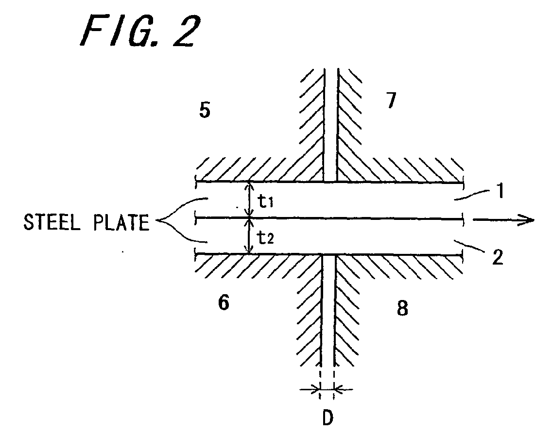
- FIG. 2 is an explanatory view showing a shear-joining
apparatus (as viewed before joining) according to the first
embodiment;
- FIG. 3 is an explanatory view showing the shear-joining
apparatus (as viewed after joining) according to the first
embodiment;
- FIG. 4 is an explanatory view showing a joint surface
according to the first embodiment;
- FIGS. 5A and 5B are overall views of a steel plate
splicing facility according to a second embodiment of the
present invention, wherein FIG. 5A shows a state during
joining, and FIG. 5B shows a state after joining;
- FIG. 6 is an explanatory view showing a shear-joining
apparatus (as viewed before joining) according to the second
embodiment;
- FIG. 7 is an explanatory view showing the shear-joining
apparatus (as viewed after joining) according to the second
embodiment;
- FIG. 8 is an explanatory view showing a joint surface
according to the second embodiment;
- FIGS. 9A and 9B are overall views of a steel plate
splicing facility according to a third embodiment of the
present invention, wherein FIG. 9A shows a state during
joining, and FIG. 9B shows a state after joining;
- FIG. 10 is an explanatory view showing a shear-joining
apparatus (as viewed after joining) according to the third
embodiment;
- FIGS. 11A and 11B are explanatory views showing a joint
surface according to the third embodiment;
- FIGS. 12A and 12B are explanatory view showing the
shearing operation according to the first embodiment;
- FIG. 13 is a graph showing the relationship between the
strength of a joint and joining temperature (steel plate
temperature);
- FIG. 14 is a graph showing the relationship between the
strength of a joint and percentage clearance;
- FIGS. 15A and 15B are views schematically showing a
conventional splicing method and a splicing method according
to the present invention, respectively; and
- FIGS. 16A and 16B are overall views of a conventional
steel plate splicing facility, wherein FIG. 16A shows a state
during joining, and FIG. 16B shows a state after joining.
-
DESCRIPTION OF THE PREFERRED EMBODIMENTS
-
Embodiments of the present invention will next be
described in detail with reference to the drawings.
[First Embodiment]
-
FIGS. 1A, 1B, 2, 3, and 4 show a steel plate splicing
facility according to a first embodiment of the present
invention.
-
As shown in FIGS. 1A and 1B, the steel plate splicing
facility according to the present embodiment includes a steel
plate heating apparatus 100 and a shear-joining apparatus 200.
A steel plate 1 having passed through the shear-joining
apparatus 200 undergoes notch treatment and joint treatment,
and is then sent to looper equipment and pickling equipment
as in the conventional facility.
-
In FIGS. 2 and 3, the preceding material overlies the
following material. However, the positional relationship
between the preceding and following materials is not limited
thereto; i.e., the following material may overlie the
preceding material. FIGS. 2 to 4 show the conditions of the
preceding and following materials in the process of and after
joining as viewed on a cross section taken along the
thickness of a steel plate (as viewed on the X-Z plane).
-
In FIGS. 1A and 1B, the clamp, punch, and punch-backing
member are vertically movable, and the die is stationary.
However, the die is not necessarily stationary, but may be
vertically movable under certain conditions.
-
The steel plate heating apparatus 100 includes a
following-material heating apparatus 31, a following-material
heating apparatus 32, and a preceding-material/following-material
heating apparatus 4, and is adapted to heat steel
plates 1 and 2 to a predetermined temperature.
-
Herein, the expression "to heat to a predetermined
temperature" means, for example, that a steel plate of the
atmospheric temperature (about 30°C) can be heated to a
temperature of 1,000°C or higher.
-
The following-material heating apparatus 31 is adapted
to heat, through induction heating, a leading end portion of
a steel plate (hereinafter referred to as a preceding
material) 1 which is currently undergoing pickling, or
pickling and cold rolling. The following-material heating
apparatus 32 is adapted to heat, through induction heating, a
leading end portion of a next steel plate (hereinafter
referred to as a following material) 2 which is to undergo
pickling, or pickling and cold rolling.
-
A method for heating the preceding material 1 is not
limited to induction heating as illustrated in FIGS. 1A and
1B. The preceding material 1 may be heated through direct or
radiant heating by use of a burner or through contact heat
conduction from a heating body. This also applies to heating
of the following material 2.
-
After the following material 2 is heated, a tail end
portion of the preceding material 1 and a leading end portion
of the following material 2 are superposed on each other.
The heating apparatus 4 grips the preceding material 1 and
the following material 2 at the overlap portion and heats the
overlap portion through contact heat conduction. The heating
apparatus 4 is a heating clamp (a high-temperature member),
which is preheated to a predetermined temperature through
induction heating.
-
The heating apparatus 4 does not necessarily need to
perform contact heat conduction, but may perform induction
heating or heating with, for example, a burner.
-
The following material 2 may be heated in the present
process instead of being heated in a separate process.
-
The shear-joining apparatus 200 includes a stationary
die 6, a clamp 5, which is vertically movable in relation to
the die 6, a vertically movable punch 7, and a punch-backing
member 8.
-
As shown in FIG. 2, an overlap portion of the preceding
material 1 and the following material 2 is gripped between
the die 6 and the clamp 5 through movement of the clamp 5
toward the die 6, and the punch 7 is pressed down toward the
punch-backing member 8 for punching. As a result, at the
overlap portion of the two steel plates, the punch 7 causes a
fracture surface of one steel plate to be brought in contact
with a fracture surface of the other steel plate.
-
In FIG. 2, the preceding material overlies the
following material. However, the positional relationship
between the preceding and following materials is not limited
thereto; i.e., the following material may overlie the
preceding material.
-
As shown in FIG. 3, after being heated, the tail end
portion of the preceding material 1 and the leading end
portion of the following material 2 are sheared, and the
respective newly-formed surfaces form a joint surface (marked
with the broken line in FIG. 3). The newly-formed surfaces
come into contact with each other at high temperature without
presence of impurities such as an oxide film therebetween.
Such impurities are usually present on the surface of a steel
plate at high temperature.
-
As shown in FIG. 2, according to the present embodiment,
the newly-formed surfaces come into contact with each other
at high temperature as a result of subjection to pressing
forces induced in the X direction or radially by the clamp 5,
the punch 7, the punch-backing member 8, and the die 6, to
thereby be joined together through diffusion of metal atoms.
-
The punch 7 and the die 6 used in the present
embodiment are formed such that, as shown in FIG. 4, the
joint surface extends linearly as viewed on the X-Y plane.
-
The steel plate splicing facility according to the
present embodiment was tested by use of steel plates. The
results of the test are shown in FIG. 13. As shown in FIG.
13, at a steel plate temperature equal to or higher than
350°C, a joint is formed under good conditions such that the
strength of the joint is higher than that of base material.
Also, as shown in FIG. 14, when the percentage clearance c/t
defined below by Eq. (1) is equal to or lower than 5%, a
joint is formed under good conditions such that the strength
of the joint is higher than that of base material.
-
The expression "good joining" appearing in FIGS. 13 and
14 means that the strength of a joint is equal to or higher
than that of base material and does not allow occurrence of
fracture of a steel plate when the steel plate undergoes
pickling, or pickling and cold rolling. The strength of base
material varies depending on base material and is peculiar to
base material. However, since the test has revealed that, at
a steel plate temperature equal to or higher than 350°C and
at a percentage clearance c/t equal to or lower than 5%, the
strength of a joint becomes equal to or higher than that of
base material, the present invention specifies the steel
plate temperature and the percentage clearance c/t as 350°C
or higher and 5% or lower, respectively. Notably, the
strength of base material is the tensile strength of base
material. FIG. 13 shows the results of the test in which the
strength of a joint was tested while the temperature of a
steel plate at the time of joining was varied as a parameter.
FIG. 14 shows the results of the test in which the strength
of a joint was tested while the percentage clearance c/t at
the time of joining was varied as a parameter.
c/t=D/(t1+t2)×100
where D is the clearance in the X direction between the punch
7 and the die 6, and t1 and t2 are the thickness of the
preceding material 1 and that of the following material 2,
respectively, as measured at their overlap portion.
-
As shown in FIGS. 15A and 15B, in contrast to the
conventional joining method such as flash butt processing and
laser processing, the method of joining steel plates
according to the present embodiment is advantageous in that
surfaces to be joined can be of low accuracy, and joining
time is very short, specifically one second or less. Thus,
the overall time of the joining process can be considerably
reduced, and looper equipment can be simplified considerably.
-
Specifically, according to the conventional method, as
marked with the broken line in FIG. 15A, a leading end
surface of the following material and a tail end surface of
the preceding material butt to each other; thus, preparation
for joining consumes about 25 seconds. By contrast,
according to the present embodiment, as marked with the
broken line in FIG. 15B, a leading end portion of the
following material and a tail end portion of the preceding
material are superposed on each other; thus, preparation time
for joining is considerably reduced from 25 seconds.
-
Furthermore, since the conventional method employs a
flash butt processing, in which voltage is applied to the
entire end surfaces, or a laser processing, in which a laser
head is moved, joining time is as long as about 10 seconds.
By contrast, according to the present embodiment, joining
time is time that the punch 7 consumes for punching (one
second or less), and is thus short.
[Second Embodiment]
-
FIGS. 5A, 5B, 6, 7, and 8 show a steel plate splicing
facility according to a second embodiment of the present
invention.
-
In FIGS. 6 and 7, the preceding material overlies the
following material. However, the positional relationship
between the preceding and following materials is not limited
thereto; i.e., the following material may overlie the
preceding material. FIGS. 6 to 8 show the condition of the
preceding and following materials in the process of and after
joining as viewed on a cross section taken along the
thickness of a steel plate (as viewed on the X-Z plane).
Notably, in order to explain the condition of a joint along
the width direction of a steel plate, FIG. 8 includes a view
showing the X-Y plane as viewed from above the steel plate.
-
In FIGS. 5A and 5B, the clamp, punch, and punch-backing
member are vertically movable, and the die is stationary.
However, the die is not necessarily stationary, but may be
vertically movable under certain conditions.
-
As shown in FIGS. 5A and 5B, the steel plate splicing
facility according to the present embodiment assumes a basic
configuration similar to that of the first embodiment and
differs from the first embodiment in that, as shown in FIG. 8,
the joint surface extends along a curved or rectangularly
bent line as viewed on the X-Y plane.
-
The punch 7 and the die 6 used in the present
embodiment are formed such that the joint surface assumes the
above-mentioned profile. The other structural feature of the
present embodiment is similar to that of the first embodiment.
-
Thus, also in the present embodiment, as shown in FIG.
6, an overlap portion of the preceding material 1 and the
following material 2 is gripped between the die 6 and the
clamp 5 through movement of the clamp 5 toward the die 6, and
the punch 7 is pressed down toward the punch-backing member 8
for punching. As a result, at the overlap portion of the two
steel plates, the punch 7 causes a fracture surface of one
steel plate to be brought in contact with a fracture surface
of the other steel plate.
-
As shown in FIG. 7, after being heated, a tail end
portion of the preceding material 1 and a leading end portion
of the following material 2 are sheared, and the respective
newly-formed surfaces form a joint surface (marked with the
broken line in FIG. 7). The newly-formed surfaces come into
contact with each other at high temperature without presence
of impurities such as an oxide film therebetween. Such
impurities are usually present on the surface of a steel
plate at high temperature.
-
As in the case of the first embodiment, the present
embodiment is also characterized in that, at a steel plate
temperature equal to or higher than 350°C, a joint is formed
under good conditions such that the strength of the joint is
higher than that of base material and that, when the
percentage clearance c/t defined above by Eq. (1) is equal to
or lower than 5%, a joint is formed under good conditions
such that the strength of the joint is higher than that of
base material.
[Third Embodiment]
-
FIGS. 9A, 9B, 10, 11A, and 11B show a steel plate
splicing facility according to a third embodiment of the
present invention.
-
In FIG. 10, the preceding material overlies the
following material. However, the positional relationship
between the preceding and following materials is not limited
thereto; i.e., the following material may overlie the
preceding material.
-
FIGS. 10, 11A, and 11B show the conditions of the
preceding and following materials in the process of and after
joining as viewed on a cross section taken along the
thickness of a steel plate (as viewed on the X-Z plane).
Notably, in order to explain the condition of a joint along
the width direction of a steel plate, FIG. 11A shows a view
of the X-Y plane as viewed from above the steel plate.
-
In FIGS. 9A and 9B, the clamp, punch, and punch-backing
member are vertically movable, and the die is stationary.
However, the die is not necessarily stationary, but may be
vertically movable under certain conditions.
-
As shown in FIGS. 9A and 9B, the steel plate splicing
facility according to the present embodiment assumes a basic
configuration similar to that of the first embodiment and
differs from the first embodiment in that, as shown in FIGS.
11A and 11B, an arbitrary number of joint surfaces are
present along the width direction of the steel plates (along
the Y direction); i.e., the joint surface is not continuously
present along the width direction of the steel plates.
-
Thus, according to the present embodiment, a shear-joining
apparatus 200 is configured such that a vertically
movable punch 7 is sandwiched between two clamps 5 which are
vertically movable in relation to corresponding stationary
dies 6. As shown in FIG. 10, the punch 7 is pressed down so
as to shear the preceding material 1 and the following
material 2, whereby the respective newly-formed surfaces are
joined together.
-
As in the case of the first embodiment, the present
embodiment is also characterized in that, at a steel plate
temperature equal to or higher than 350°C, a joint is formed
under good conditions such that the strength of the joint is
higher than that of base material and that, when the
percentage clearance c/t defined above by Eq. (1) is equal to
or lower than 5%, a joint is formed under good conditions
such that the strength of the joint is higher than that of
base material.
-
In the present embodiment, a joint has a cylindrical
joint surface. However, the present invention is not limited
thereto. The joint surface may have any shape such as a
rectangular shape.