EP1382376A1 - Dispositif de melange et de distribution d'un fluide dense et d'un fluide leger place en amont d'un lit granulaire et son utilisation en ecoulement descendant - Google Patents
Dispositif de melange et de distribution d'un fluide dense et d'un fluide leger place en amont d'un lit granulaire et son utilisation en ecoulement descendant Download PDFInfo
- Publication number
- EP1382376A1 EP1382376A1 EP03291653A EP03291653A EP1382376A1 EP 1382376 A1 EP1382376 A1 EP 1382376A1 EP 03291653 A EP03291653 A EP 03291653A EP 03291653 A EP03291653 A EP 03291653A EP 1382376 A1 EP1382376 A1 EP 1382376A1
- Authority
- EP
- European Patent Office
- Prior art keywords
- liquid
- chimneys
- gas
- reactor
- level
- Prior art date
- Legal status (The legal status is an assumption and is not a legal conclusion. Google has not performed a legal analysis and makes no representation as to the accuracy of the status listed.)
- Granted
Links
Images

Classifications
-
- B—PERFORMING OPERATIONS; TRANSPORTING
- B01—PHYSICAL OR CHEMICAL PROCESSES OR APPARATUS IN GENERAL
- B01D—SEPARATION
- B01D53/00—Separation of gases or vapours; Recovering vapours of volatile solvents from gases; Chemical or biological purification of waste gases, e.g. engine exhaust gases, smoke, fumes, flue gases, aerosols
- B01D53/14—Separation of gases or vapours; Recovering vapours of volatile solvents from gases; Chemical or biological purification of waste gases, e.g. engine exhaust gases, smoke, fumes, flue gases, aerosols by absorption
- B01D53/18—Absorbing units; Liquid distributors therefor
- B01D53/185—Liquid distributors
-
- B—PERFORMING OPERATIONS; TRANSPORTING
- B01—PHYSICAL OR CHEMICAL PROCESSES OR APPARATUS IN GENERAL
- B01F—MIXING, e.g. DISSOLVING, EMULSIFYING OR DISPERSING
- B01F23/00—Mixing according to the phases to be mixed, e.g. dispersing or emulsifying
- B01F23/20—Mixing gases with liquids
-
- B—PERFORMING OPERATIONS; TRANSPORTING
- B01—PHYSICAL OR CHEMICAL PROCESSES OR APPARATUS IN GENERAL
- B01J—CHEMICAL OR PHYSICAL PROCESSES, e.g. CATALYSIS OR COLLOID CHEMISTRY; THEIR RELEVANT APPARATUS
- B01J8/00—Chemical or physical processes in general, conducted in the presence of fluids and solid particles; Apparatus for such processes
- B01J8/02—Chemical or physical processes in general, conducted in the presence of fluids and solid particles; Apparatus for such processes with stationary particles, e.g. in fixed beds
- B01J8/0278—Feeding reactive fluids
Definitions
- the present invention relates to a device for optimizing the mixing and distribution of two fluids constituted for the first of a phase essentially gaseous comprising most often at least in part hydrogen, and for the second of a liquid phase essentially composed of hydrocarbons, said device being placed upstream of a granular bed or between two granular beds successive.
- granular beds is meant a set of solid particles having the grain form, these grains can have any shape but most often approximately cylindrical or spherical, and having dimensions typical of the order of a few millimeters. These granular solids have advantageously a catalytic activity.
- the device for mixing and dispensing of the present invention is integrated into a reactor can contain one or more successive fixed granular beds and separated between them, in which the flow of liquid and gaseous phases is co-current descending through the said fixed bed or beds of granular solids.
- reactors for which the liquid flows to be dispensed are generally between 0.5 and 100 kg / m 2 / s and more usually between 10 and 80 kg / m 2 / s.
- the present invention finds in particular an application in all cases where the gas phase is a minority compared to the liquid phase, that is to say where the volume ratio between the gas and the liquid is less than 1, but it can also be used when the gaseous phase is in the majority compared to the liquid phase, that is to say when the volume ratio between the gas and the liquid is often greater than 3/1 and usually less than 400/1.
- the field of the invention therefore extends to volume ratios between the gas and the liquid between 0 and 400, 0 excluded.
- the invention also applies in cases where the reaction is highly exothermic and requires the introduction into the reactor of an additional fluid, most often gaseous, to cool the gas / liquid mixture.
- the present invention also applies to the case where the reaction requires close contact to allow the dissolution of a compound, most often gaseous, for example hydrogen H 2 , in the liquid phase.
- gaseous for example hydrogen H 2
- the present invention applies in particular in the field of gas / liquid distributors, such as for example those used for carrying out hydrotreatment reactions, for example hydrocracking, hydrodesulfurization, hydrodenitrogenation, hydrogenations selective or total cuts C 2 to C 5 .
- the invention also applies to the cases of the selective hydrogenation of steam cracking essences, the hydrogenation of aromatic compounds in aliphatic and / or naphthenic cuts, and the hydrogenation of olefins in aromatic cuts.
- the patent FR 2 745 202 and the patent US 5,688,445 thus propose a tray for chimneys with storied holes along the chimney for the passage of gas (upper holes) and liquid (lower holes).
- No system is provided in this prior art to prevent fluctuations of the liquid / gas interface above the plateau due to the injection of liquid at the head of the reactor. Indeed, because of their configuration, any imbalance of this interface necessarily results in a imbalance of gas and liquid flows from one chimney to another, which is obviously damaging to the homogeneity of the mixture.
- WO 95/35159 proposes a two-level distribution system.
- the first level consists of a circular plate with edges intended for dampen the impact of the gas / liquid flow entering the reactor.
- the liquid then flows from this first tray to the distributor tray through tubes, the base of which has slots. These tubes are not in liquid charge and a certain amount of gas can therefore flow in mixture with the liquid.
- This first plateau must calm the oscillations of the liquid level on the second plateau or distributor plate, but the gas entrainment at the level of the downpipes can produce foaming at the liquid guard of the distributor plate and thus degrading the supply to the distribution chimneys.
- the second level is consisting of a tray with chimneys pierced with holes in their part located in above the tray and in their part located below the tray.
- US patent 4,140,625 proposes a system of plates crossed by venturis. The gas is injected at the top of these venturis and the liquid is injected at the neck or upstream of the converging. The gas / liquid mixture is then injected into the bed Catalytic. This system has the disadvantage of offering only a low flexibility in flow liquid since there is only one level of holes for the liquid.
- US patent 5,799,877 proposes a distributor tray system in which the gas and liquid are injected through concentric tubes, the tube for injecting the gas being located in the center.
- the height of the liquid introduction tubes is variable depending on the injection points.
- This invention therefore has the disadvantage of providing a density of variable liquid injection points depending on the liquid flow.
- lowest liquid flow rates which are precisely the most difficult to achieve distribute, benefit from the lowest number of injection points.
- none system is not designed to absorb fluctuations in the liquid level above the plateau which would be due to the impact of the gas / liquid flow at the inlet of the reactor.
- the platform offers great flexibility in liquid flow but has no means to stabilize the gas / liquid interface upstream of the platform, i.e. the platform has two levels to absorb fluctuations in the gas / liquid interface, but only offers flexibility reduced in liquid flow.
- the subject of the present invention is a device making it possible to mix two fluids, one light gas, the other liquid, dense, and the most homogeneous distribution possible of this mixture over the entire section of the reactor in upstream of a bed of granular solid.
- the device comprises a substantially horizontal tray, covering the entire section of the reaction vessel and supporting a multiplicity of substantially vertical chimneys and advantageously constant section, comprising an upper end communicating with the part of the reactor located above the tray, a lower end communicating with the part of the reactor located below the plate, the said chimneys being pierced with lateral orifices allowing the introduction of the dense fluid and of a part of the light fluid inside the said chimneys, and the said device being characterized by a tubular system for feeding the dense fluid from the outside of the reactor to a level between the plate and that of at least one lateral orifice of the chimneys in contact with the dense fluid, the tubular system having slots for exit of the dense fluid fully immersed in said volume surmounting the plate.
- the first fluid, the least dense, is injected through the inlet of the reactor upstream of the plate.
- the second, densest fluid can be injected via a tubular system comprising a substantially vertical main tube advantageously supplemented by a multiplicity of substantially horizontal secondary tubes described below, this tubular system comprising a multiplicity of orifices preferably opening at a level situated slightly above the level of the plate supporting the chimneys, and this level being entirely immersed in the volume of this second fluid surmounting the plate.
- the two fluids being injected separately upstream of the tray, a flat interface is established between the volume of the second fluid resting on the tray supporting the chimneys, and the volume of the first fluid which occupies the space left free between the upper part of the second fluid and the upper part of the reactor.
- the system described in this invention makes it possible to maintain this interface, between the volume of the second fluid and the volume of the first fluid, flat and horizontal so as to control a homogeneous supply of the various perforated chimneys, by each of the two fluids. More specifically, the major part of the first fluid is introduced into the chimneys through orifices located at the upper end of said chimneys and through a first part of the lateral orifices arranged in several levels along the chimneys, and the second fluid is introduced through a second part of these lateral orifices located below the first part.
- This system avoids the phenomena of bubbling or foaming which can appear in the volume of dense fluid and disturb the supply of chimneys.
- the present device makes it possible to guarantee that the supply of the chimneys by the dense fluid is done well according to a homogeneous physical state of this dense fluid and identical from one chimney to another, and not according to a more or less less aerated by the presence of a part of the light fluid in the dense fluid in the form of an emulsion or very fine bubbles, as is possible when the interface between the two fluids is disturbed.
- the liquid and gaseous phases can circulate in co-current downward flow through the said bed or beds of granular solids.
- the density of the chimneys expressed in number of chimneys per m 2 of reactor section will generally be between 100 and 700 per m 2 and preferably between 150 and 500 per m 2 .
- the lateral orifices will be distributed along chimneys on at least two levels, the lowest level being located at a distance between 100 and 300 mm from the level where the tubular system, and the successive levels being distant from each other by at least 20 mm.
- the chimneys can be extended below the level of the plateau by a distance (h), this distance (h) preferably being between 10 and 100 mm.
- the distance (d) between the end lower chimneys of the upper level of the bed will be between 0 and 50 mm, 0 excluded, and preferably between 0 and 20 mm, 0 excluded.
- essentially gaseous phase is meant a phase containing at least 50% of gas, preferably at least 70% of gas, and even more preferably at least 90% of gas.
- essentially liquid phase is meant a phase containing at least 50% liquid, preferably at least 70% liquid, and even more preferably at least 90% liquid.
- the present invention allows great flexibility in terms of liquid flow, and guarantees the absence of fluctuations in the level of the gas / liquid interface.
- the arrival of the phases and their introduction into the reactor can take place in the mixed state. So that the invention can nevertheless be implemented, it is then necessary to have at the head of the reactor a system for separating this mixed phase so as to have at the outlet of said separation system, an essentially gaseous phase and a essentially liquid phase in the sense given above.
- This separation system is an integral part of the present invention when the gas and liquid phases are introduced as a mixture into the reactor.
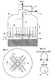
- Figures 1 and 2 show schematically an embodiment of the mixing system and distribution when that is placed at the head of a first granular bed of the reactor and when the fluids to be mixed can be introduced separately into the reactor.
- Figures 3A and 3B show a section through the perforated tubes.
- Figures 4 and 5 show schematically an exemplary embodiment of the mixing system and distribution when the one is placed at the head of the reactor or between two beds successive granular, and when the fluids to be mixed can be introduced separately in the reactor.
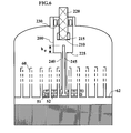
- FIG. 6 shows an exemplary embodiment of the mixing and distribution preferably placed upstream of a first granular bed, when the fluids to be brought into contact are introduced into the reactor as a mixture.
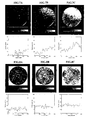
- Figures 7a; 7b; 7c are visualizations of the distribution of the dense fluid over a section of the reactor obtained by gamma tomography without the tubular system liquid supply, for different gas flow rates.
- Figures 8a; 8b; 8c are visualizations of the distribution of the dense fluid over a section of the reactor obtained by gamma tomography with the tubular system liquid supply, for the same gas flow rates as in the case of Figures 7a; 7b; 7c.
- the reactor shown diagrammatically in FIG. 1 is an elongated fixed bed reactor (10) containing one or more successive beds, which operates in gas / liquid flow with downward cocurrent.
- a liquid charge (12) is injected near the head of the reactor, through a line (2), into at least one tube (50) which will also be called a tubular system.
- a gaseous charge (11) is injected into one or more levels of the reactor (10), at least one of these levels being located at the head of the reactor.
- the gas charge is injected at the head of the reactor via a line (1).
- a pressure compensation system (13) composed of a control valve controlled by a differential pressure sensor, makes it possible to evacuate a part of liquid flow to line (1).
- a substantially horizontal plate (62) covering the entire section of the reactor is adhered to the wall of said reactor and supports a plurality of chimneys (60) open at their upper end and having along their side wall a series of orifices of passage (63) of either substantially circular or elongated shape. These chimneys are substantially parallel to the axis of the reactor.
- the liquid is advantageously injected as close as possible to the plate using at least one substantially vertical tube (50) possibly provided with slots (53) for the outlet of said fluid, these slots being arranged on the periphery at the bottom of the tube. (50).
- the slots of the tube are entirely immersed in the volume of liquid above the plate defined by the plate and a level of the orifices for lateral passage of the liquid, these orifices being preferably entirely submerged.
- the tube (50) can also be extended by a series of substantially horizontal tubes (51) provided with liquid outlet orifices (54).
- the tube (50) is connected to the liquid injection line (2) after passing through the wall of the reactor (10).
- the level at which the perforated tubes (51) or the peripheral slots (53) of the tube (50) are located is located below the lowest level (in the direction of fluid flow) of the side passage sections (63 ) or lateral openings of the chimneys (60) so that these perforated tubes (51) are immersed in a volume of liquid which feeds one or more levels of the lateral passage sections (63) of the chimneys (60).
- the liquid is thus injected directly via the line (2) and then passes into the supply tube (50) then the tubes (51) or the slots (53).
- the tubes (51) or the slots (53) are entirely immersed in the liquid volume retained by the plate (62).
- the present invention makes it possible, unlike the devices of the prior art involving chimneys, to maintain a stable and horizontal gas / liquid interface. Indeed, when numerous chimneys intended for the distribution of fluids are arranged on a tray to best cover the section of the reactor, it is of primary importance to create a stable and horizontal gas / liquid interface to ensure an identical supply of fluids between the different chimneys.
- the distance between the level of the tubes (51) or the top of the slots (53) and the lowest level of the lateral passage sections (63) of the chimneys (60), will be greater than 50 mm and preferably between 100 mm and 300 mm.
- the supply tube (s) (50) will generally be located in place of one or more chimneys (60), in a region close to the axis of the reactor, and the tubes (51) will be arranged along an approximately horizontal axis, between the rows of chimneys (60). Eight tubes (51) can thus be arranged between the chimneys (60), whether the pitch between these chimneys is triangular or square.
- Figure 2 shows an example of distribution of the tubes (51) in the case where the pitch between chimneys (60) is triangular.
- FIGS 3A and 3B show a section of a tube (51) and describe two examples of outlet section located on these tubes.
- the outlet sections (54) located on the tubes (51) may be orifices (54) of various sizes, or nozzles (55) with a substantially constant and circular passage section, or with a variable passage section so as to present a convergent part followed by a divergent part.
- These orifices (54) or nozzles (55) are arranged along the length of the tubes (51), substantially along a horizontal axis, and are directed generally downwards.
- the angle ( ⁇ ) between the axis of the orifices or nozzles and the vertical will be between -90 ° and 90 ° and preferably between -45 ° and 45 °, positively counting the angles located on the right half with respect to the vertical axis passing through the tubes (51), and negatively the angles located on the left half with respect to this same axis.
- the speed of injection of the liquid will be determined so that the tube (50) is always filled with liquid.
- the speed of injection of the liquid at the level of the orifices or nozzles for the outlet of the tubes (51) or of the slots (53) will generally be between 0.5 and 5 m / s. This speed range therefore allows a range of variation in liquid feed rate from 1 to 10.
- the lateral passage sections (63), arranged on several levels along the chimneys (60) are not specifically assigned to the passage of the liquid phase or the vapor phase, but will be distributed naturally as a function of the position of the interface, in an upper group with respect to this interface which will see the gas phase pass, and a lower group with respect to said interface which will see the liquid phase pass.
- This interface has the property of being flat and remaining very well defined over the entire range of gas and liquid flow rates envisaged, due to the characteristics of the device according to the present invention, particularly of the liquid introduction system (50).
- a given lateral passage section (63), and all the passage sections (63) belonging to the same level, will therefore see passing either the liquid phase or the gas phase, as a function of the respective flow rates of these phases. It is clear that the greater the flow of liquid phase, the higher the interface between said liquid phase and the gas phase, but this level will never exceed the level of the upper end of the chimneys ( 60).
- the operating principle of the device according to the present invention consists in carrying out a pre-mixing of the liquid and gas phases in the chimneys (60) before injecting this mixture at different points of the entry of the bed through the open lower ends of the say chimneys (65).
- the lateral orifices (63) can be of various shapes, for example they can be in the form of orifices, or one or more slots. These lateral openings are arranged on at least two different levels, preferably between 3 and 10 levels, of which at least one level, located lowest, is used for the passage of the liquid and at least one level, located highest, is used for the passage of gas.
- the geometry of the chimneys (60) thus allows great flexibility of use of the plate in terms of variation of the liquid flow and the gas flow.
- the distance between two levels of consecutive orifices or slots is greater than 20 mm and preferably at least 50 mm.
- the maximum width of the lateral passage section which corresponds, depending on the case, to the maximum width in the case of a slot, or to the maximum diameter in the case of an orifice, will advantageously be less than 75% the diameter of a chimney and usually more than 2 mm.
- a certain density of chimneys will be necessary. This density will generally be between 100 and 700 chimneys / m 2 of bed section, and preferably between 150 and 500 chimneys / m 2 .
- the distance (H) between the level of the lowest passage sections along the chimneys (60) and the level of the tubes (51) or the level of the top of the slots (53) will generally be greater than 100 mm and preferably between 100 and 300 mm.
- This distance firstly has the effect of leaving a sufficient volume of liquid to dissipate the kinetic energy of the liquid jets coming from the tubes (51) through the orifices (54) or the nozzles (55) or slots (53), and to prevent these jets of liquid from disturbing the gas / liquid interface which must remain as much as possible, parallel to the plate (62).
- This distance also has the effect of lengthening the residence time of the liquid gas mixture in the chimneys (60), and therefore of optimizing the mass transfer between the gas and the liquid.
- the chimneys (60) of the tray (62) thus play the role of a static mixer.
- the chimneys (60) will advantageously be extended by a distance (h) below the chimney support plate (62) in order to prevent part of the liquid from spreading under the underside of the plate (62) and to reduce the space between the point of exit of the mixture and the entry into the bed.
- the distance (h) will preferably be between 10 and 100 mm.
- the distance between the lower end of the tubes (60) and the top of the bed will preferably be between 0 and 50 mm, 0 excluded and even more preferably between 0 and 20 mm, 0 excluded.
- inert spherical particles 70
- a guard bed to maintain distribution of intact gas and liquid fluids to the catalytic bed.
- the thickness of this layer will generally be greater than 50 mm, preferably between 80 and 500 mm, and even more preferably, between 100 and 300 mm.
- the diameter of the inert spherical particles used will generally be greater than 6 mm and preferably greater than 15 mm.
- Figures 4 and 5 show a second embodiment of the distribution system according to the invention when it is arranged at the reactor head, upstream of the first bed or between two successive beds, and when at least one of the fluids to be mixed is introduced directly from outside the reactor.
- the primary fluid is injected along the axis of the reactor.
- This fluid can be the gaseous feed when the system is located at the head of the reactor or a gas / liquid mixture coming from an upstream granular bed when the system is located between two successive granular beds.
- the secondary fluid is injected by a system of perforated tubes (120) whose main tube (110) passes through the side wall of the reactor.
- the secondary fluid can be the liquid feed when the system is located at the head of the reactor or a liquid or gaseous effluent intended to cool the gas / liquid mixture coming from an upper bed when the system is located between two successive granular beds.
- the mixing and the distribution of the primary fluid and the secondary fluid takes place through perforated chimneys (60) arranged on a plate (62).
- the characteristics of these chimneys (60) are identical to those described in the first example.
- the tube (110) called the main tube, is arranged substantially horizontally between two rows of chimneys and can be extended by side secondary tubes (120) connected to the main tube and also extending along a substantially horizontal axis or simply perforated by circular, elliptical or rectangular holes.
- the secondary tubes (120) are preferably located in the same plane as the main tube. Generally, the distance between the level of the tubes (110) and (120) and the lowest level of the lateral passage sections (63) located on the chimneys (60) will be greater than 50 mm and preferably between 100 and 500 mm. This distance allows the kinetic energy of the liquid or gaseous jets from the tubes (120) to dissipate so as not to disturb the gas / liquid interface located above the plate. In addition, when the secondary fluid aims to cool the gas / liquid mixture coming from a granular bed located upstream, this distance makes it possible to increase the contact time necessary to achieve good heat exchange.
- Figure (5) shows an example configuration from above, of the network of tubes (120) used for the injection of the secondary fluid in the case where the pitch between the chimneys (60) is square.
- the secondary tubes (120) are arranged substantially orthogonally to the main tube (110).
- the characteristics of the outlet sections of the secondary tubes (120) are the same as those described in FIG. (3).
- the outlet sections of the tubes (120) or (110) may be orifices (54) of various shapes or nozzles (55), the passage section of which may be approximately constant and circular or variable so as to have a converging portion followed of a divergent part.
- orifices or nozzles will be directed generally downwards, and preferably the angle (57) between the axis of the orifice and the vertical will be between -90 ° and 90 °, and preferably between -45 ° and 45 °.
- the speed of injection of the liquid at the level of the orifices (54) or of the nozzles (55) will be between 0.5 and 3 m / s.
- the injection speed at the orifices (54) or the nozzles (55) will advantageously be between 0.5 and 5 m / s. This speed range therefore allows a range of variation in gas flow from 1 to 10.
- Figure (6) shows a third embodiment of the dispensing device according to the invention when it is arranged at the head of the reactor, and when the fluids to be mixed and dispensed are introduced as a mixture, which will also be called mixed phase, in the reactor.
- these fluids are generally introduced in the form of a downward co-current two-phase flow.
- the distribution system always consists of a chimney tray (60) having lateral passage sections (63) for supplying the two fluids, but it is preceded by a separation system (200 ) allowing the separation of the two fluids upstream of the plate (62).
- the introduction of the gaseous fluid resulting from this separation at the head of the reactor is done by means of lateral outlet windows (230), and the introduction of the liquid fluid resulting from said separation at the level of the plate (62) is done by a system of concentric tubes (240) and (245) which feed the network of tubes (51) under the same conditions as in the case previously described.
- the characteristics of the chimneys (60) are identical to those described in the first example.
- the separation system (200) consists of a central cylindrical tube (210) terminated by at least one tangential outlet (215) for the liquid and by at least one tangential outlet for the gas (230), imposing the flow a rotation of at least 90 ° relative to the axis of the tube.
- This system allows rapid separation of a gas / liquid mixture whose ratio of mass flow rates of gas to liquid is between 0.1 and 10.
- the number of tangential outlets for the gas and for the liquid is between 1 and 4, preferably equal to two for each phase.
- the ratio of the opening sections of each tangential outlet to the passage section of the tube (210) is between 0.25 and 1, and preferably between 0.4 and 0.6.
- the ratio between the height and the width of the tangential outlet (215) is generally between 1 and 4, preferably substantially equal to 2.
- a propeller (220) can be added inside the tube (210) and upstream of the tangential outlets (215. This propeller (220) can be single revolution or double revolution.
- the ratio of the width of the propeller, corresponding to the cross-section of the fluids, to the diameter of the tube can be between 0.5 and 1.
- the number of propeller steps i.e. the ratio of the total height of the propeller to the pitch of the propeller
- the fluids from the tube (210) are recovered in an enclosure (225) whose diameter is greater than twice the diameter of the tube (210) and less than 90% of the diameter of the reactor.
- the purpose of this enclosure is to dampen the fluctuations in the flow rate of the liquid to be injected at the level of the plate (62).
- the gas is discharged from the enclosure (225) through the tangential outlet sections (230).
- These outlet sections may consist, for example, of holes of circular or elliptical shape, or of slots of rectangular shape.
- the ratio of the total area of the outlet sections (230), i.e. the sum of the areas of the sections (230) divided by the area of the section of the tube (210) will be between 0.5 and 4 , preferably substantially equal to 2.
- the distance (p) separating the outlet sections (230) from the outlet sections (215) will generally be at least 50 mm and in particular between 100 and 300 mm.
- the liquid is discharged from the enclosure (225) using at least one tube (240) whose upper end is connected to the bottom of the enclosure (225) and whose lower end is connected to the minus a horizontal perforated tube (51).
- the outlet sections of the tubes (51) may be orifices (54) of various sizes or nozzles (55), the passage section of which may be approximately constant and circular or variable, so as to have a convergent part followed by a divergent part.
- orifices (54) or nozzles (55) will be directed generally downwards and preferably the angle (57) between the axis of the orifice and the vertical will be between -90 ° and 90 °, and preferably between -45 ° and 45 °.
- the diameter of the orifices (54) or of the nozzles (55) will be calculated so as to keep the tube (240) filled with liquid, or more generally with dense fluid over the entire range of flow of this fluid.
- the flow variation range will therefore correspond to the variation in the height of the level of the dense fluid in the enclosure (225). This level will always be less than the distance separating the bottom of the tube (210) from the bottom of the enclosure (225).
- a second enclosure discharge tube (225) can be added. This second tube (245), generally concentric and located inside the tube (240), opens into the enclosure (225) by its upper end which serves as an inlet for the dense fluid.
- This upper end of the tube (245) is located at a distance h e from the bottom of the enclosure (225) so that this second tube (245) is only used when the dense fluid flow corresponds to a dense fluid level. in the enclosure (225) greater than the distance h e .
- This tube (245) is also connected at its lower part to at least one perforated tube (52) of the same type as the perforated tubes (51).
- This tube (245) can be concentric with the tube (240) as shown in Figure (5) or independent from the tube (240).
- the characteristics of the tubes (52) are the same as those of the tubes (51).
- the passage diameter of the outlet orifices or nozzles of the tubes (52) is calculated so that the level of dense fluid in the enclosure (225) at the maximum flow rate of this dense fluid, never exceeds the distance between the bottom of the enclosure (225) and the lower end of the tube (210).
- a comparative test was carried out between a conventional system consisting of a tray with perforated chimneys supplied by a co-current gas / liquid flow and a system, as described in FIG. 4, comprising a tray with perforated chimneys supplied with liquid by a radial tube. Both systems have been tested on a 400 mm diameter reactor.
- the reference distribution system or according to the prior art, consists of a tray on which are fixed 55 chimneys of diameter 15 mm. fireplaces are perforated with 20 circular 7 mm diameter holes spanning 10 levels between 50 and 250 mm from the level of the plate.
- the distribution system was directly supplied by a Downward co-current gas / liquid flow introduced substantially according to the direction of the vertical axis, at the top of the reactor.
- the distribution system as described in the present application consists of a tray on which are fixed 55 chimneys (60) with a diameter of 15 mm.
- the chimneys (60) are perforated with 16 circular orifices 7 mm in diameter located on 8 levels ranging between 90 and 250 mm from the level of the plate.
- the liquid is introduced using a tube (110) passing through the side wall of the reactor according to the geometry described in figure n ° 4.
- This tube is perforated with 68 holes of diameter 7 mm arranged approximately equally, according to the following angles (57) relative to the vertical of: -45 °, -30 °, 30 ° and 45 °.
- the liquid velocity at the level of these orifices is equal to 3.8 m / s.
- the distance between the level of the orifices of the tube (110) and the lowest level of the orifices of the chimneys is 50 mm.
- Figure 7 shows a comparison of the distribution of the gas rate measured in the catalytic bed using a gamma ray tomograph located at a distance of 500 mm from the bottom of the chimneys (60).
- Figures 7 and 8 show the image of the gas rate measured respectively when the conventional distribution system is used and when the system described according to the invention is implemented.
- the color scale ranges from black for a gas rate of zero (liquid flow only) to white for a gas rate of 60%.
- the liquid flow rate reported in the vacuum section of the reactor is 56 kg / m 2 / h
- the gas flow rate is 0.2 kg / m 2 / h ( Figure 7a and 8a), 0.5 Kg / m2 / h ( Figure 7b and 8b) and 1 kg / m 2 / h ( Figure 7c and 8c).
- Figure 7a and 8a the distribution of gas over the section of the bed is markedly degraded in that the figures (7) show gray levels much less uniform than those figures (8).
- the gas rate is not at all homogeneous over the entire section.
- the liquid level is unbalanced at the level of the tray and the chimneys are not all supplied in the same way.
- the system as described according to the invention makes it possible to obtain a homogeneous distribution of the gas over the entire section of the bed.
- the gas rate profiles obtained on a reactor diameter are all very horizontal.
- the efficiency of the distribution system remains excellent when the volume gas content in the gas / liquid mixture varies from 20 to 50%.
Landscapes
- Chemical & Material Sciences (AREA)
- Chemical Kinetics & Catalysis (AREA)
- Engineering & Computer Science (AREA)
- Analytical Chemistry (AREA)
- General Chemical & Material Sciences (AREA)
- Oil, Petroleum & Natural Gas (AREA)
- Organic Chemistry (AREA)
- Devices And Processes Conducted In The Presence Of Fluids And Solid Particles (AREA)
Abstract
Description
L'invention s'applique également dans les cas où la réaction est fortement exothermique et nécessite l'introduction dans le réacteur d'un fluide supplémentaire, le plus souvent gazeux, pour refroidir le mélange gaz/liquide.
Le premier fluide, le moins dense, est injecté par l'entrée du réacteur en amont du plateau. Le second fluide, le plus dense, peut être injecté par l'intermédiaire d'un système tubulaire comprenant un tube principal sensiblement vertical avantageusement complété d'une multiplicité de tubes secondaires sensiblement horizontaux décrits plus loin, ce système tubulaire comportant une multiplicité d'orifices débouchant de préférence à un niveau situé légèrement au dessus du niveau du plateau supportant les cheminées, et ce niveau étant entièrement immergé dans le volume de ce second fluide surmontant le plateau. Les deux fluides étant injectés séparément à l'amont du plateau, une interface plane s'établit entre le volume du second fluide reposant sur le plateau supportant les cheminées, et le volume du premier fluide qui occupe l'espace laissé libre entre la partie supérieure du second fluide et la partie supérieure du réacteur. Le système décrit dans cette invention permet de maintenir cette interface, entre le volume du second fluide et le volume du premier fluide, plane et horizontale de manière à contrôler une alimentation homogène des différentes cheminées perforées, par chacun des deux fluides. Plus précisément, la majeure partie du premier fluide est introduite dans les cheminées par des orifices situés à l'extrémité supérieure des dites cheminées et par une première partie des orifices latéraux disposés selon plusieurs niveaux le long des cheminées, et le second fluide est introduit par une seconde partie de ces orifices latéraux située au dessous de la première partie. Ce système permet d'éviter les phénomènes de bouillonnement ou de moussage qui peuvent apparaítre dans le volume de fluide dense et perturber l'alimentation des cheminées. Plus précisément, le présent dispositif permet de garantir que l'alimentation des cheminées par le fluide dense se fasse bien selon un état physique homogène de ce fluide dense et identique d'une cheminée à l'autre, et non pas selon un état plus ou moins aéré par la présence d'une partie du fluide léger dans le fluide dense sous forme d'une émulsion ou de très fines bulles, comme cela est possible lorsque l'interface entre les deux fluides est perturbée.
La densité des cheminées exprimée en nombre de cheminées par m2 de section de réacteur sera généralement comprise entre 100 et 700 par m2 et préférentiellement entre 150 et 500 par m2.
Par phase essentiellement gazeuse, on entend une phase contenant au moins 50% de gaz, de préférence au moins 70% de gaz, et de manière encore plus préférée au moins 90% de gaz. Par phase essentiellement liquide, on entend une phase contenant au moins 50% de liquide, de préférence au moins 70% de liquide, et de manière encore plus préférée au moins 90% de liquide.
Dans certains cas, l'arrivée des phases et leur introduction dans le réacteur peut se faire à l'état mixte. Pour que l'invention puisse néanmoins être mise en oeuvre, il faut alors disposer en tête du réacteur un système de séparation de cette phase mixte de manière à disposer en sortie du dit système de séparation, d'une phase essentiellement gazeuse et d'une phase essentiellement liquide au sens qui a été donné un peu plus haut. Ce système de séparation fait partie intégrante de la présente invention lorsque les phases gazeuse et liquide sont introduites en mélange dans le réacteur.
Une charge gazeuse (11) est injectée en un ou plusieurs niveaux du réacteur (10), au moins un de ces niveaux étant situé en tête du réacteur. La charge gazeuse est injectée en tête du réacteur par une ligne (1). En cas de montée en pression du système tubulaire (50) ou de la ligne (2), un système de compensation de pression (13) composé d'une vanne de régulation asservie à un capteur de pression différentiel, permet d'évacuer une partie du débit liquide vers la ligne (1).
Un plateau (62) sensiblement horizontal et couvrant toute la section du réacteur est adhérent à la paroi du dit réacteur et supporte une pluralité de cheminées (60) ouvertes à leur extrémité supérieure et présentant le long de leur paroi latérale une série d'orifices de passage (63) de forme soit sensiblement circulaire, soit allongée. Ces cheminées sont sensiblement parallèles à l'axe du réacteur.
Le liquide est injecté avantageusement au plus près du plateau à l'aide d'au moins un tube sensiblement vertical (50) éventuellement muni de fentes (53) de sortie du dit fluide, ces fentes étant disposées sur la périphérie en partie basse du tube (50). Les fentes du tube sont entièrement immergées dans le volume de liquide au dessus du plateau défini par le plateau et un niveau des orifices de passage latéral du liquide, ces orifices étant de préférence entièrement immergés. Le tube (50) pourra également être prolongé par une série de tubes sensiblement horizontaux (51) munis d'orifices de sortie du liquide (54). Le tube (50) est raccordé à la ligne d'injection du liquide (2) après avoir traversé la paroi du réacteur (10).
Le niveau auquel sont situés les tubes perforés (51) ou les fentes périphériques (53) du tube (50) est situé au dessous du niveau le plus bas (dans le sens de l'écoulement des fluides) des sections de passage latérales (63) ou orifices latéraux des cheminées (60) de telle sorte que ces tubes perforés (51) sont immergés dans un volume de liquide qui alimente un ou plusieurs niveaux des sections de passages latérales (63) des cheminées( 60). Le liquide est ainsi injecté directement via la ligne (2) et passe ensuite dans le tube d'alimentation (50) puis les tubes (51) ou les fentes (53).
Les tubes (51) ou les fentes (53) sont entièrement immergés dans le volume liquide retenu par le plateau (62). De cette façon, la présente invention permet, à la différence des dispositifs de l'art antérieur faisant intervenir des cheminées, de maintenir une interface gaz/liquide stable et horizontale. En effet, lorsque de nombreuses cheminées destinées à la distribution des fluides sont disposées sur un plateau pour couvrir au mieux la section du réacteur, il est de première importance de créer une interface gaz/liquide stable et horizontale pour assurer une alimentation en fluides identique entre les différentes cheminées.
De façon à ce que l'installation du système d'injection du liquide limite le moins possible le nombre de points d'injection gaz/liquide, le ou les tube(s) d'alimentation (50) seront généralement situés à la place d'une ou plusieurs cheminées (60), dans une région voisine de l'axe du réacteur, et les tubes (51) seront disposés selon un axe approximativement horizontal, entre les rangées de cheminées (60). Huit tubes (51) peuvent ainsi être disposés entre les cheminées (60), que le pas entre ces cheminées soit triangulaire ou carré.
Ces orifices (54) ou buses (55) sont disposés sur la longueur des tubes (51), sensiblement selon un axe horizontal, et sont dirigés généralement vers le bas. De façon préférée, l'angle (α) entre l'axe des orifices ou buses et la verticale sera compris entre -90° et 90° et de préférence compris entre -45° et 45°, en comptant positivement les angles situés sur la moitié droite par rapport à l'axe vertical traversant les tubes (51), et négativement les angles situés sur la moitié gauche par rapport à ce même axe.
La vitesse d'injection du liquide sera déterminée de façon à ce que le tube (50) soit toujours rempli de liquide. La vitesse d'injection du liquide au niveau des orifices ou buses de sortie des tubes (51) ou des fentes (53) sera en général comprise entre 0,5 et 5 m/s. Cette gamme de vitesse permet donc une plage de variation en débit d'alimentation liquide de 1 à 10.
Il faut donc noter que les sections de passage latérales (63), disposées sur plusieurs niveaux au long des cheminées (60) ne sont pas spécifiquement affectées au passage de la phase liquide ou de la phase vapeur, mais se répartiront naturellement en fonction de la position de l'interface, en un groupe supérieur par rapport à cet interface qui verra passer la phase gaz, et un groupe inférieur par rapport au dit interface qui verra passer la phase liquide.
Cet interface a la propriété d'être plan et de rester très bien défini sur toute la plage de débits gaz et liquide envisagée, en raison des caractéristiques du dispositif selon la présente invention, particulièrement du système d'introduction du liquide (50). Une section de passage (63) latérale donnée, et l'ensemble des sections de passage (63) appartenant au même niveau, verront donc passer soit la phase liquide soit la phase gaz , en fonction des débits respectifs de ces phases.
Il est clair que plus le débit de phase liquide sera important, plus l'interface entre la dite phase liquide et la phase gaz sera situé à un niveau élevé, mais ce niveau ne dépassera toutefois jamais le niveau de l'extrémité supérieure des cheminées (60).
Les orifices latéraux (63) peuvent être de forme diverse, par exemple ils peuvent se présenter sous forme d'orifices, ou d'une ou plusieurs fentes. Ces orifices latéraux sont disposés sur au moins deux niveaux différents, de préférence entre 3 et 10 niveaux, dont au moins un niveau, situé le plus bas, est utilisé pour le passage du liquide et au moins un niveau, situé le plus haut, est utilisé pour le passage du gaz. La géométrie des cheminées (60) permet ainsi une grande souplesse d'utilisation du plateau en terme de variation du débit liquide et du débit gaz.
La distance entre deux niveaux d'orifices ou de fentes consécutifs est supérieure à 20 mm et de préférence d'au moins 50 mm. La largeur maximale de la section de passage latérale qui correspond selon les cas à la largeur maximale s'il s'agit d'une fente, ou au diamètre maximum s'il s'agit d'un orifice, sera avantageusement inférieure à 75 % du diamètre d'une cheminée et habituellement supérieur à 2 mm. Pour assurer une bonne répartition des points d'injection du mélange gaz liquide résultant en tête de lit catalytique, une certaine densité de cheminées sera nécessaire. Cette densité sera en général comprise entre 100 et 700 cheminées/m2 de section de lit , et de préférence comprise entre 150 et 500 cheminées/m2. La distance (H) entre le niveau des sections de passage situé le plus bas le long des cheminées (60) et le niveau des tubes (51) ou le niveau du haut des fentes (53) sera en général supérieure à 100 mm et de préférence comprise entre 100 et 300 mm.
Cette distance a d'abord pour effet de laisser un volume de liquide suffisant pour dissiper l'énergie cinétique des jets de liquide issus des tubes (51) par les orifices (54) ou les buses (55) ou des fentes (53), et d'éviter que ces jets de liquide ne perturbent l'interface gaz/liquide qui doit rester autant que possible, parallèle au plateau (62). Cette distance a de plus pour effet d'allonger le temps de séjour du mélange gaz liquide dans les cheminées (60), et donc d'optimiser le transfert de masse entre le gaz et le liquide. Les cheminées ( 60) du plateau (62) jouent ainsi le rôle d'un mélangeur statique.
Enfin les cheminées (60) seront avantageusement prolongées d'une distance (h )en dessous de la plaque de support des cheminées (62) afin d'éviter qu'une partie du liquide se propage sous la face inférieure du plateau (62) et de diminuer l'espace compris entre le point de sortie du mélange et l'entrée dans le lit. La distance (h) sera de préférence comprise entre 10 et 100 mm.
Ensuite, afin d'éviter la séparation du mélange liquide gaz avant son injection dans le lit, la distance entre l'extrémité inférieure des tubes (60) et le haut du lit sera de préférence comprise entre 0 et 50 mm, 0 exclu et de manière encore plus préférée entre 0 et 20 mm, 0 exclu.
Ce fluide peut être la charge gazeuse lorsque le système est situé en tête de réacteur ou un mélange gaz/liquide issu d'un lit granulaire amont lorsque le système est situé entre deux lits granulaires successifs. Le fluide secondaire est lui injecté par un système de tubes perforés (120) dont le tube principal (110) traverse la paroi latérale du réacteur.
Le fluide secondaire peut être la charge liquide lorsque le système est situé en tête de réacteur ou un effluent liquide ou gazeux destiné à refroidir le mélange gaz/liquide issu d'un lit supérieur lorsque le système est situé entre deux lits granulaires successifs. Le mélange et la distribution du fluide primaire et du fluide secondaire s'effectue à travers des cheminées perforées (60) disposées sur un plateau (62).
Les caractéristiques de ces cheminées (60) sont identiques à celles décrites dans le premier exemple. Le tube (110), appelé tube principal, est disposé de manière sensiblement horizontale entre deux rangées de cheminées et peut être prolongé de tubes secondaires (120) latéraux raccordées au tube principal et s'étendant également selon un axe sensiblement horizontal ou simplement perforé par des orifices circulaires, elliptiques ou rectangulaires.
Les tubes secondaires (120) sont de préférence situés dans le même plan que le tube principal. De façon générale, la distance entre le niveau des tubes (110) et (120) et le niveau situé le plus bas des sections de passage latérales (63) situées sur les cheminées (60) sera supérieure à 50 mm et de préférence comprise entre 100 et 500 mm.
Cette distance permet à l'énergie cinétique des jets liquide ou gazeux issus des tubes (120) de se dissiper afin de ne pas perturber l'interface gaz/liquide situé au dessus du plateau. De plus lorsque le fluide secondaire a pour but de refroidir le mélange gaz/liquide issu d'un lit granulaire situé en amont, cette distance permet d'augmenter le temps de contact nécessaire pour réaliser un bon échange thermique.
Les sections de sortie des tubes (120) ou (110) pourront être des orifices (54) de formes diverses ou des buses (55) dont la section de passage peut être approximativement constante et circulaire ou variable de manière à présenter une partie convergente suivie d'une partie divergente.
Ces orifices ou buses seront dirigés généralement vers le bas, et de façon préférée l'angle (57) entre l'axe de l'orifice et la verticale sera compris entre -90° et 90°, et de préférence compris entre -45° et 45°. Lorsque le fluide secondaire est liquide, la vitesse d'injection du liquide au niveau des orifices (54) ou des buses (55) sera comprise entre 0,5 et 3 m/s. Lorsque le fluide secondaire est gazeux, la vitesse d'injection au niveau des orifices (54) ou des buses (55) sera avantageusement comprise entre 0.5 et 5 m/s. Cette gamme de vitesse permet donc une plage de variation en débit de gaz de 1 à 10.
Dans ce cas, le système de distribution est toujours constitué d'un plateau à cheminées (60) disposant de sections de passage latérales (63) pour l'alimentation des deux fluides, mais, il est précédé d'un système de séparation (200) permettant la séparation des deux fluides à l'amont du plateau (62). L'introduction du fluide gazeux résultant de cette séparation en tête du réacteur se fait au moyen de fenêtres de sortie latérales (230), et l'introduction du fluide liquide résultant de la dite séparation au niveau du plateau (62) se fait par un système de tubes concentriques (240) et (245) qui alimentent le réseau de tubes (51) dans les mêmes conditions que dans le cas précédemment décrit.
Les caractéristiques des cheminées (60) sont identiques à celles décrites dans le premier exemple. Le système de séparation (200) est constitué d'un tube cylindrique central (210) terminé par au moins une sortie tangentielle (215) pour le liquide et par au moins une sortie tangentielle pour le gaz (230), imposant à l'écoulement une rotation d'au moins 90° par rapport à l'axe du tube.
Ce système, déjà décrit dans le brevet FR 2 798 864, permet une séparation rapide d'un mélange gaz/liquide dont le rapport des débits massiques du gaz sur le liquide est compris entre 0,1 et 10. Le nombre de sorties tangentielles pour le gaz et pour le liquide est compris entre 1 et 4, de préférence égal à deux pour chaque phase. A titre d'exemple, le rapport des sections d'ouverture de chaque sortie tangentielle sur la section de passage du tube (210) est compris entre 0,25 et 1, et de préférence entre 0,4 et 0,6.
Le rapport entre la hauteur et la largeur de la sortie tangentielle (215) est en général compris entre 1 et 4, de préférence sensiblement égal à 2. A l'intérieur du tube (210) et en amont des sorties tangentielles (215), une hélice (220) peut être ajoutée. Cette hélice (220) peut être à simple révolution ou à double révolution. Le rapport de la largeur de l'hélice, correspondant à la section de passage des fluides, sur la diamètre du tube peut être compris entre 0,5 et 1.
Le nombre de pas de l'hélice (soit le rapport de la hauteur totale de l'hélice sur le pas de l'hélice) est compris généralement entre 1 et 6, et préférentiellement entre 2 et 3.
Le gaz est évacué de l'enceinte (225) à travers les sections de sortie tangentielles (230). Ces sections de sortie peuvent être constituées par exemple d'orifices de forme circulaire ou elliptique, ou de fentes de forme rectangulaire. Le rapport de l'aire totale des sections de sortie (230), c'est à dire la somme des aires des sections (230) divisée par l'aire de la section du tube (210) sera compris entre 0,5 et 4, de préférence sensiblement égal à 2.
La distance (p) séparant les sections de sortie (230) des sections de sortie (215) sera en général au moins égale à 50 mm et en particulier comprise entre 100 et 300 mm. Le liquide est évacué de l'enceinte (225) à l'aide d'au moins un tube (240) dont l'extrémité supérieure est raccordé au fond de l'enceinte (225) et dont l'extrémité inférieure est raccordée à au moins un tube perforé horizontal (51).
Les sections de sortie des tubes (51) pourront être des orifices (54) de taille diverse ou des buses (55) dont la section de passage pourra être approximativement constante et circulaire ou variable, de manière à présenter une partie convergente suivie d'une partie divergente. Ces orifices (54) ou buses (55) seront dirigés généralement vers le bas et de façon préférée l'angle (57) entre l'axe de l'orifice et la verticale sera compris entre -90° et 90°, et de préférence compris entre -45° et 45°. Le diamètre des orifices (54) ou des buses (55) sera calculé de façon à maintenir le tube (240) rempli de liquide, ou plus généralement de fluide dense sur toute la plage de débit de ce fluide. La plage de variation de débit correspondra donc à la variation de la hauteur du niveau du fluide dense dans l'enceinte (225).
Ce niveau sera toujours inférieur à la distance séparant le bas du tube (210) du fond de l'enceinte (225). Pour augmenter la plage de débit en fluide dense, un deuxième tube d'évacuation de l'enceinte (225) peut être ajouté. Ce deuxième tube (245), généralement concentrique et situé à l'intérieur du tube (240), débouche dans l'enceinte (225) par son extrémité supérieure qui sert d'orifice d'entrée du fluide dense.
Les caractéristiques des tubes (52) sont les mêmes que celles des tubes (51). Le diamètre de passage des orifices ou buses de sortie des tubes (52) est calculé de façon à ce que le niveau en fluide dense dans l'enceinte (225) au débit maximum de ce fluide dense, ne dépasse jamais la distance comprise entre le fond de l'enceinte (225) et l'extrémité inférieure du tube (210).
Comme on peut le constater en l'absence d'un système d'amenée du liquide, la distribution du gaz sur la section du lit est nettement dégradée en ce sens que les figures (7) montrent des niveaux de gris beaucoup moins uniformes que ceux des figures (8). En effet, comme le montrent les profils obtenus sur un diamètre du réacteur, le taux de gaz n'est pas du tout homogène sur toute la section.
En effet, le niveau liquide est déséquilibré au niveau du plateau et les cheminées ne sont pas toutes alimentées de la même façon. Par contre, le système tel que décrit selon l'invention permet d'obtenir une distribution homogène du gaz sur toute la section du lit. Les profils de taux de gaz obtenus sur un diamètre de réacteurs sont tous très horizontaux. L'efficacité du système de distribution reste excellente lorsque le taux de gaz volumique dans le mélange gaz/liquide varie de 20 à 50 %.
Claims (20)
- Dispositif de mélange et de répartition d'un fluide dense, généralement liquide, et d'un fluide léger, généralement gazeux, placé dans une enceinte réactionnelle en amont d'un lit granulaire ou entre deux lits granulaires successifs, le dit dispositif comportant :un plateau (62) sensiblement horizontal, couvrant toute la section de l'enceinte réactionnelle et supportantune multiplicité de cheminées (60) sensiblement verticales comportant une extrémité supérieure communiquant avec la partie du réacteur située au dessus du plateau (62), une extrémité inférieure communiquant avec la partie du réacteur située au dessous du plateau (62), les dites cheminées étant percées d'orifices latéraux (63), permettant l'introduction du fluide dense et d'une partie du fluide léger à l'intérieur des cheminées (60), le dit dispositif étant caractérisé par un système tubulaire (50) d'amenée du fluide dense depuis l'extérieur du réacteur dans un volume compris entre le plateau et le niveau d'au moins un orifice latéral (63) des cheminées en contact avec le fluide dense, le système tubulaire présentant des fentes de sortie du fluide dense entièrement immergées dans ledit volume surmontant le plateau (62).
- Dispositif de mélange et de répartition suivant la revendication 1 dans lequel le système tubulaire est situé à un niveau voisin du niveau du plateau.
- Dispositif selon l'une des revendications 1 à 2 dans lequel la densité des cheminées est comprise entre 100 et 700 par m2 de section de réacteur, et préférentiellement comprise entre 150 et 500 par m2 de section de réacteur.
- Dispositif selon l'une des revendications 1 à 3 dans lequel les orifices latéraux (63) sont répartis le long des cheminées ( 60) sur plusieurs niveaux, le niveau le plus bas étant situé à une distance comprise entre 100 et 300 mm par rapport au niveau où débouche le système tubulaire (50).
- Dispositif selon l'une des revendications 1 à 4 dans lequel les cheminées (60) sont prolongées d'une distance h au dessous du niveau du plateau (62), cette distance h étant préférentiellement comprise entre 10 et 100 mm.
- Dispositif selon les revendications 1 à 5 dans lequel la distance (d) séparant l'extrémité inférieure des cheminées (60) du niveau supérieur du lit situé immédiatement au dessous est comprise entre 0 et 50 mm, 0 exclu, et de préférence comprise entre 0 et 20 mm, 0 exclu.
- Dispositif selon l'une des revendications 1 à 6 dans lequel le système tubulaire (50) comprend un tube principal sensiblement vertical et une multiplicité de tubes secondaires (51) sensiblement horizontaux munis d'orifices de sortie (54).
- Dispositif selon l'une des revendications 1 à 7 dans lequel le système tubulaire (50) comprend un tube sensiblement vertical muni à son extrémité inférieure de fentes latérales (53) situées à une distance par rapport au niveau le plus bas des orifices latéraux (63) des cheminées (60), comprise entre 100 mm et 500 mm.
- Dispositif selon l'une des revendications 7 à 8 dans lequel les orifices de sortie (54) des tubes secondaires (51) sont dirigés vers le bas en formant un angle par rapport à la verticale qui est compris entre -90 et + 90° et préférentiellement compris entre -45° et + 45°.
- Dispositif selon l'une des revendications 7 à 9 dans lequel les orifices de sortie (54) des tubes secondaires (51) ont la forme de buse à section sensiblement constante.
- Dispositif selon l'une des revendications 7 à 10 dans lequel les orifices de sortie (54) des tubes secondaires (51) ont la forme de buse à section variable de manière à présenter dans le sens d'écoulement du fluide une partie convergente suivie d'une partie divergente.
- Dispositif selon l'une des revendications 1 à 11 dans lequel les orifices latéraux ( 63) des cheminées (60) sont réparties sur au moins deux niveaux, les dits niveaux étant distants entre eux d'au moins 20 mm.
- Dispositif selon l'une des revendications 1 à 12 dans lequel la largeur maximale des sections de passage (63), ou leur diamètre lorsqu'elles sont circulaires, est inférieure à 75 % du diamètre des cheminées (60) et supérieure à 2 mm.
- Dispositif selon l'une des revendications 1 à 13 dans lequel on ajoute en tête du réacteur un système de séparation (200) des phases gaz et liquide lorsque les fluides à distribuer sont introduits en mélange, le dit système de séparation comprenant un tube cylindrique (210) muni d'internes permettant une mise en rotation et une séparation du dit mélange.
- Dispositif selon la revendication 14 dans lequel le système de séparation (200) possède de 1 à 4 sorties tangentielles pour la phase liquide (215) et pour la phase gaz (230), le rapport de l'aire totale des sections de sortie du gaz (230), c'est à dire la somme des aires des sections (230) divisée par l'aire de la section du tube (210) étant compris entre 0,5 et 4 fois la section de passage du tube cylindrique (210), et préférentiellement sensiblement égal à 2.
- Dispositif selon l'une des revendications 14 à 15 dans lequel les sorties tangentielles( 215) pour le liquide et (230) pour le gaz du système de séparation (200), sont distantes d'une distance (p) supérieure à 50 mm et préférentiellement comprise entre 100 mm et 300 mm.
- Dispositif selon l'une des revendications 14 à 16 dans lequel le tube cylindrique (210) du système de séparation (200) contient une hélice dont le nombre de pas est compris entre 1 et 6, et préférentiellement entre 2 et 3.
- Utilisation du dispositif selon l'une quelconque des revendications 1 à 17 dans un procédé d'hydrotraitement d'hydrocarbures.
- Utilisation du dispositif selon la revendication 18 dans des réacteurs à co courant descendant de gaz et de liquide dans lesquels le rapport volumique gaz sur liquide est compris entre 0 et 400, 0 exclu.
- Utilisation du dispositif selon la revendication 19 dans des réacteurs à co courant descendant de gaz et de liquide, le flux de liquide étant compris entre 0,5 et 100 kg/m2/seconde et préférentiellement compris entre 10 et 80 kg/m2/seconde.
Applications Claiming Priority (2)
| Application Number | Priority Date | Filing Date | Title |
|---|---|---|---|
| FR0209076A FR2842435B1 (fr) | 2002-07-16 | 2002-07-16 | Dispositif de melange et de distribution d'un fluide dense et d'un fluide leger place en amont d'un lit granulaire et son utilisation en ecoulement descendant |
| FR0209076 | 2002-07-16 |
Publications (2)
| Publication Number | Publication Date |
|---|---|
| EP1382376A1 true EP1382376A1 (fr) | 2004-01-21 |
| EP1382376B1 EP1382376B1 (fr) | 2008-07-02 |
Family
ID=29763903
Family Applications (1)
| Application Number | Title | Priority Date | Filing Date |
|---|---|---|---|
| EP03291653A Expired - Lifetime EP1382376B1 (fr) | 2002-07-16 | 2003-07-03 | Dispositif de mélange et de distribution d'un fluide dense et d'un fluide léger placé en amont d'un lit granulaire et son utilisation en écoulement descendant |
Country Status (7)
| Country | Link |
|---|---|
| US (1) | US7250142B2 (fr) |
| EP (1) | EP1382376B1 (fr) |
| JP (1) | JP4697572B2 (fr) |
| KR (1) | KR101015929B1 (fr) |
| DE (1) | DE60321864D1 (fr) |
| DK (1) | DK1382376T3 (fr) |
| FR (1) | FR2842435B1 (fr) |
Cited By (5)
| Publication number | Priority date | Publication date | Assignee | Title |
|---|---|---|---|---|
| WO2008021917A3 (fr) * | 2006-08-09 | 2008-08-28 | Amt Int Inc | Distillation extractive triphasique avec de multiples colonnes connectées en série |
| EP3037164A1 (fr) * | 2014-12-23 | 2016-06-29 | Haldor Topsøe A/S | Réacteur chimique catalytique de séparation de particules et séparateur de particules |
| CN109701299A (zh) * | 2018-12-25 | 2019-05-03 | 重庆纳斯美科技发展有限公司 | 一种涂料除泡机 |
| CN114768482A (zh) * | 2022-03-09 | 2022-07-22 | 山东神驰石化有限公司 | 一种异戊橡胶装置的溶剂回收装置 |
| CN116440682A (zh) * | 2023-03-01 | 2023-07-18 | 武汉船用电力推进装置研究所(中国船舶集团有限公司第七一二研究所) | 一种净化装置 |
Families Citing this family (15)
| Publication number | Priority date | Publication date | Assignee | Title |
|---|---|---|---|---|
| GB0220338D0 (en) * | 2002-09-02 | 2002-10-09 | Secretary Trade Ind Brit | Production of variable concentration fluid mixtures |
| FR2853260B1 (fr) | 2003-04-02 | 2005-05-06 | Inst Francais Du Petrole | Dispositif ameliore de melange et de distribution d'une phase gaz et d'une phase liquide alimentant un lit granulaire |
| US7473405B2 (en) * | 2004-10-13 | 2009-01-06 | Chevron U.S.A. Inc. | Fluid distribution apparatus for downflow multibed poly-phase catalytic reactor |
| FR2883200B1 (fr) * | 2005-03-17 | 2007-05-11 | Inst Francais Du Petrole | Dispositif pour le melange et la repartition d'un gaz et d' un liquide en amont d'un lit granulaire |
| US20080257147A1 (en) * | 2005-12-06 | 2008-10-23 | Johnson Matthey Plc | Gas Distributor |
| WO2008155399A1 (fr) * | 2007-06-21 | 2008-12-24 | Basf Se | Réacteur en vue de la réalisation d'une réaction triphasique entre une phase liquide et une phase gazeuse sur un lit fixe de catalyseur |
| DE102011103634A1 (de) * | 2011-06-08 | 2012-12-13 | Linde Aktiengesellschaft | Flüssigkeitsverteiler |
| JP5998915B2 (ja) * | 2012-12-19 | 2016-09-28 | 富士電機株式会社 | 排ガス処理装置 |
| CN104906947B (zh) * | 2015-05-18 | 2017-11-14 | 南京泽众环保科技有限公司 | 氨气分布系统 |
| CN105195036A (zh) * | 2015-09-18 | 2015-12-30 | 宁波天工机械密封有限公司 | 混合搅拌机 |
| FR3065171B1 (fr) * | 2017-04-13 | 2021-02-12 | Saipem Sa | Dispositif de double distribution de liquide utile dans une colonne de fractionnement ou de lavage sur un support flottant |
| US10441932B2 (en) * | 2017-06-28 | 2019-10-15 | Uop Llc | Apparatus for vapor-liquid distribution |
| TWI826653B (zh) * | 2019-03-27 | 2023-12-21 | 美商科氏格利奇有限合夥公司 | 用於質量傳遞柱的二階段液體分布裝置及在質量傳遞柱內分布液體之方法 |
| CN111676056A (zh) * | 2020-06-19 | 2020-09-18 | 中耐工程科技有限公司 | 具有立体网格进料结构的渣油加氢反应器、含有该反应器的渣油加氢系统及其渣油加氢工艺 |
| TWI764774B (zh) * | 2021-07-02 | 2022-05-11 | 信紘科技股份有限公司 | 氣液混合裝置及方法 |
Citations (6)
| Publication number | Priority date | Publication date | Assignee | Title |
|---|---|---|---|---|
| FR703029A (fr) * | 1930-09-24 | 1931-04-22 | Dispositif d'arrosage pour tours d'absorption, de lavage et analogues | |
| US5014740A (en) * | 1990-05-21 | 1991-05-14 | Cameron Gordon M | Distributor for packed tower |
| WO1995035159A1 (fr) * | 1994-06-20 | 1995-12-28 | Mobil Oil Corporation | Systeme de distribution de deux phases pour reacteurs a ecoulement descendant |
| US5679290A (en) * | 1996-09-16 | 1997-10-21 | Cameron; Gordon M. | Packed absorption towers |
| US5688445A (en) * | 1995-07-31 | 1997-11-18 | Haldor Topsoe A/S | Distributor means and method |
| US6042090A (en) * | 1997-05-16 | 2000-03-28 | Sulzer Chemtech Ag | Distributor device for a column |
Family Cites Families (14)
| Publication number | Priority date | Publication date | Assignee | Title |
|---|---|---|---|---|
| GB1450715A (en) * | 1973-12-07 | 1976-09-29 | British Petroleum Co | Multi-bed reactors |
| GB8721964D0 (en) * | 1987-09-18 | 1987-10-28 | Shell Int Research | Multitube reactor |
| US4839108A (en) * | 1987-12-21 | 1989-06-13 | Mobil Oil Corp. | Liquid distribution device and pan |
| US5799877A (en) * | 1996-01-03 | 1998-09-01 | Exxon Research And Engineering Company | Fluid distribution across a particulate bed |
| FR2745820B1 (fr) * | 1996-03-08 | 1998-04-17 | Inst Francais Du Petrole | Conversion du gaz de synthese en hydrocarbures en presence d'une phase liquide |
| US5837208A (en) * | 1996-06-12 | 1998-11-17 | Uop | Hydroprocessing reactor mixer/distributor |
| US6017443A (en) * | 1998-02-05 | 2000-01-25 | Mobil Oil Corporation | Hydroprocessing process having staged reaction zones |
| US6554994B1 (en) * | 1999-04-13 | 2003-04-29 | Chevron U.S.A. Inc. | Upflow reactor system with layered catalyst bed for hydrotreating heavy feedstocks |
| FR2798864B1 (fr) * | 1999-09-24 | 2001-12-14 | Inst Francais Du Petrole | Systeme de separation gaz/liquide intervenant dans un procede de conversion d'hydrocarbures |
| FR2807673B1 (fr) * | 2000-04-17 | 2003-07-04 | Inst Francais Du Petrole | Dispositif de distribution d'un melange polyphasique sur un lit de solide granulaire comportant un element brise-jet poreux |
| FR2813024B1 (fr) * | 2000-08-17 | 2004-02-13 | Inst Francais Du Petrole | Dispositif d'injection d'un fluide place entre deux lits successifs permettant de realiser et de distribuer simultanement un melange polyphasique |
| FR2813023B1 (fr) * | 2000-08-17 | 2003-10-24 | Inst Francais Du Petrole | Dispositif de distribution permettant de realiser un melange polyphasique et reacteur associe |
| WO2002048286A1 (fr) * | 2000-12-11 | 2002-06-20 | Shell Internationale Research Maatschappij B.V. | Mélangeur à chambre de turbulence pour liquides |
| FR2832075B1 (fr) * | 2001-11-09 | 2005-02-04 | Inst Francais Du Petrole | Dispositif de distribution d'un melange polyphasique sur un lit de solide granulaire comportant un element brise jet poreux a rebords |
-
2002
- 2002-07-16 FR FR0209076A patent/FR2842435B1/fr not_active Expired - Fee Related
-
2003
- 2003-07-03 DE DE60321864T patent/DE60321864D1/de not_active Expired - Lifetime
- 2003-07-03 EP EP03291653A patent/EP1382376B1/fr not_active Expired - Lifetime
- 2003-07-03 DK DK03291653T patent/DK1382376T3/da active
- 2003-07-15 KR KR1020030048403A patent/KR101015929B1/ko not_active Expired - Fee Related
- 2003-07-16 US US10/619,557 patent/US7250142B2/en not_active Expired - Fee Related
- 2003-07-16 JP JP2003275473A patent/JP4697572B2/ja not_active Expired - Fee Related
Patent Citations (6)
| Publication number | Priority date | Publication date | Assignee | Title |
|---|---|---|---|---|
| FR703029A (fr) * | 1930-09-24 | 1931-04-22 | Dispositif d'arrosage pour tours d'absorption, de lavage et analogues | |
| US5014740A (en) * | 1990-05-21 | 1991-05-14 | Cameron Gordon M | Distributor for packed tower |
| WO1995035159A1 (fr) * | 1994-06-20 | 1995-12-28 | Mobil Oil Corporation | Systeme de distribution de deux phases pour reacteurs a ecoulement descendant |
| US5688445A (en) * | 1995-07-31 | 1997-11-18 | Haldor Topsoe A/S | Distributor means and method |
| US5679290A (en) * | 1996-09-16 | 1997-10-21 | Cameron; Gordon M. | Packed absorption towers |
| US6042090A (en) * | 1997-05-16 | 2000-03-28 | Sulzer Chemtech Ag | Distributor device for a column |
Cited By (11)
| Publication number | Priority date | Publication date | Assignee | Title |
|---|---|---|---|---|
| WO2008021917A3 (fr) * | 2006-08-09 | 2008-08-28 | Amt Int Inc | Distillation extractive triphasique avec de multiples colonnes connectées en série |
| EP3037164A1 (fr) * | 2014-12-23 | 2016-06-29 | Haldor Topsøe A/S | Réacteur chimique catalytique de séparation de particules et séparateur de particules |
| WO2016102342A1 (fr) * | 2014-12-23 | 2016-06-30 | Haldor Topsøe A/S | Réacteur chimique catalytique de séparation de particules et séparateur de particules |
| US10159950B2 (en) | 2014-12-23 | 2018-12-25 | Haldor Topsøe As | Particle separating catalytic chemical reactor and particle separator |
| US10328407B2 (en) | 2014-12-23 | 2019-06-25 | Haldor Topsøe A/S | Particle separating catalytic chemical reactor and particle separator |
| EA034191B1 (ru) * | 2014-12-23 | 2020-01-15 | Хальдор Топсёэ А/С | Каталитический химический реактор с разделением частиц и сепаратор частиц |
| CN109701299A (zh) * | 2018-12-25 | 2019-05-03 | 重庆纳斯美科技发展有限公司 | 一种涂料除泡机 |
| CN109701299B (zh) * | 2018-12-25 | 2021-01-08 | 重庆纳斯美科技发展有限公司 | 一种涂料除泡机 |
| CN114768482A (zh) * | 2022-03-09 | 2022-07-22 | 山东神驰石化有限公司 | 一种异戊橡胶装置的溶剂回收装置 |
| CN114768482B (zh) * | 2022-03-09 | 2023-06-23 | 山东神驰石化有限公司 | 一种异戊橡胶装置的溶剂回收装置 |
| CN116440682A (zh) * | 2023-03-01 | 2023-07-18 | 武汉船用电力推进装置研究所(中国船舶集团有限公司第七一二研究所) | 一种净化装置 |
Also Published As
| Publication number | Publication date |
|---|---|
| FR2842435B1 (fr) | 2004-09-24 |
| US7250142B2 (en) | 2007-07-31 |
| DK1382376T3 (da) | 2008-11-03 |
| JP2004130301A (ja) | 2004-04-30 |
| JP4697572B2 (ja) | 2011-06-08 |
| DE60321864D1 (de) | 2008-08-14 |
| FR2842435A1 (fr) | 2004-01-23 |
| EP1382376B1 (fr) | 2008-07-02 |
| KR101015929B1 (ko) | 2011-02-23 |
| US20040086435A1 (en) | 2004-05-06 |
| KR20040030232A (ko) | 2004-04-09 |
Similar Documents
| Publication | Publication Date | Title |
|---|---|---|
| EP1382376B1 (fr) | Dispositif de mélange et de distribution d'un fluide dense et d'un fluide léger placé en amont d'un lit granulaire et son utilisation en écoulement descendant | |
| EP1180393B1 (fr) | Réacteur avec dispositif de mélange. | |
| EP1147809B1 (fr) | Dispositif de distribution d'un mélange polyphasique sur un lit de solide granulaire comportant un élément brisejet poreux | |
| EP1464383B1 (fr) | Réacteur comprenant un dispositif de mélange et de distribution d'une phase gaz et d'une phase liquide alimentant un lit granulaire et procédé d'hydrogénation sélective l'utilisant | |
| CA2343844C (fr) | Sous-ensemble polyfonctionnel assurant la mise en contact, la distribution de matiere et l'echange de chaleur et/ou de matiere d'au moins une phase gazeuse et d'au moins une phaseliquide | |
| EP2739383B1 (fr) | Plateau distributeur d'un gaz et d'un liquide, reacteur equipe d'un tel plateau et utilisation dudit plateau | |
| EP1866068B1 (fr) | Dispositif pour le melange et la repartition d'un gaz et d'un liquide en amont d'un lit granulaire | |
| EP2813283B1 (fr) | Dispositif de distribution d'un fluide | |
| CA2462450C (fr) | Dispositif de distribution d'un melange polyphasique sur un lit de solide granulaire comportant un element brise jet poreux a rebords | |
| EP1922391A1 (fr) | Plateau filtrant pour reacteur a lit fixe a co-courant descendant de gaz et de liquide | |
| FR2813023A1 (fr) | Dispositif de distribution permettant de realiser un melange polyphasique et reacteur associe | |
| EP2162207B1 (fr) | Enceinte contenant un lit granulaire et une distribution d'une phase gazeuse et d'une phase liquide circulant en un écoulement ascendant dans cette enceinte. | |
| EP1032464A1 (fr) | Distributeur de liquide pour colonne de distillation non verticale, et colonne de distillation ainsi equipee | |
| FR3050658A1 (fr) | Dispositif de melange et de distribution avec zones de melange et d'echange et deflecteurs. | |
| FR2861605A1 (fr) | Methode de melange et de distribution d'une phase liquide et d'une phase gazeuse | |
| CA2751523A1 (fr) | Dispositif de distribution d'un melange polyphasique comportant un plateau brise-jet perfore avec differents types de trous | |
| FR2484864A1 (fr) | Distributeur d'alimentation d'un reacteur a courant ascendant | |
| FR2818559A1 (fr) | Dispositif permettant de realiser une injection separee et une distribution homogene de deux fluides | |
| FR2824495A1 (fr) | Enceinte reactionnelle de forme allongee le long d'un axe contenant au moins un lit de catalyseur solide et au moins une boite de contact, de melange et de trempe | |
| EP1646444B1 (fr) | Plateau de distribution d'une phase gazeuse et d'une phase liquide | |
| CA2751499A1 (fr) | Dispositif de distribution d'un melange polyphasique comportant un plateau brise-jet avec element de separation | |
| CA3071466C (fr) | Dispositif de melange et de distribution avec ouverture longitudinale | |
| CA3071466A1 (fr) | Dispositif de melange et de distribution avec ouverture longitudinale | |
| WO2016066387A1 (fr) | Reacteur comprenant un dispositif de distribution et de separation gaz/liquide avec nuage gazeux reduit | |
| FR2964326A1 (fr) | Dispositif de distribution d'un melange polyphasique comportant un plateau brise-jet perfore avec differents types de trous |
Legal Events
| Date | Code | Title | Description |
|---|---|---|---|
| PUAI | Public reference made under article 153(3) epc to a published international application that has entered the european phase |
Free format text: ORIGINAL CODE: 0009012 |
|
| AK | Designated contracting states |
Kind code of ref document: A1 Designated state(s): AT BE BG CH CY CZ DE DK EE ES FI FR GB GR HU IE IT LI LU MC NL PT RO SE SI SK TR |
|
| AX | Request for extension of the european patent |
Extension state: AL LT LV MK |
|
| 17P | Request for examination filed |
Effective date: 20040721 |
|
| AKX | Designation fees paid |
Designated state(s): DE DK FR GB IT NL |
|
| GRAP | Despatch of communication of intention to grant a patent |
Free format text: ORIGINAL CODE: EPIDOSNIGR1 |
|
| GRAS | Grant fee paid |
Free format text: ORIGINAL CODE: EPIDOSNIGR3 |
|
| GRAA | (expected) grant |
Free format text: ORIGINAL CODE: 0009210 |
|
| AK | Designated contracting states |
Kind code of ref document: B1 Designated state(s): DE DK FR GB IT NL |
|
| REG | Reference to a national code |
Ref country code: GB Ref legal event code: FG4D Free format text: NOT ENGLISH |
|
| REF | Corresponds to: |
Ref document number: 60321864 Country of ref document: DE Date of ref document: 20080814 Kind code of ref document: P |
|
| REG | Reference to a national code |
Ref country code: DK Ref legal event code: T3 |
|
| PLBE | No opposition filed within time limit |
Free format text: ORIGINAL CODE: 0009261 |
|
| STAA | Information on the status of an ep patent application or granted ep patent |
Free format text: STATUS: NO OPPOSITION FILED WITHIN TIME LIMIT |
|
| 26N | No opposition filed |
Effective date: 20090403 |
|
| REG | Reference to a national code |
Ref country code: FR Ref legal event code: CD |
|
| REG | Reference to a national code |
Ref country code: DE Ref legal event code: R081 Ref document number: 60321864 Country of ref document: DE Owner name: IFP ENERGIES NOUVELLES, FR Free format text: FORMER OWNER: INSTITUT FRANCAIS DU PETROLE, RUEIL-MALMAISON, HAUTS-DE-SEINE, FR Effective date: 20110331 |
|
| REG | Reference to a national code |
Ref country code: FR Ref legal event code: PLFP Year of fee payment: 14 |
|
| REG | Reference to a national code |
Ref country code: FR Ref legal event code: PLFP Year of fee payment: 15 |
|
| REG | Reference to a national code |
Ref country code: FR Ref legal event code: PLFP Year of fee payment: 16 |
|
| PGFP | Annual fee paid to national office [announced via postgrant information from national office to epo] |
Ref country code: DE Payment date: 20180730 Year of fee payment: 16 Ref country code: NL Payment date: 20180724 Year of fee payment: 16 Ref country code: IT Payment date: 20180731 Year of fee payment: 16 Ref country code: FR Payment date: 20180725 Year of fee payment: 16 |
|
| PGFP | Annual fee paid to national office [announced via postgrant information from national office to epo] |
Ref country code: GB Payment date: 20180724 Year of fee payment: 16 Ref country code: DK Payment date: 20180724 Year of fee payment: 16 |
|
| REG | Reference to a national code |
Ref country code: DE Ref legal event code: R119 Ref document number: 60321864 Country of ref document: DE |
|
| REG | Reference to a national code |
Ref country code: DK Ref legal event code: EBP Effective date: 20190731 |
|
| GBPC | Gb: european patent ceased through non-payment of renewal fee |
Effective date: 20190703 |
|
| PG25 | Lapsed in a contracting state [announced via postgrant information from national office to epo] |
Ref country code: NL Free format text: LAPSE BECAUSE OF NON-PAYMENT OF DUE FEES Effective date: 20190801 Ref country code: GB Free format text: LAPSE BECAUSE OF NON-PAYMENT OF DUE FEES Effective date: 20190703 Ref country code: DE Free format text: LAPSE BECAUSE OF NON-PAYMENT OF DUE FEES Effective date: 20200201 |
|
| REG | Reference to a national code |
Ref country code: NL Ref legal event code: MM Effective date: 20190801 |
|
| PG25 | Lapsed in a contracting state [announced via postgrant information from national office to epo] |
Ref country code: FR Free format text: LAPSE BECAUSE OF NON-PAYMENT OF DUE FEES Effective date: 20190731 |
|
| PG25 | Lapsed in a contracting state [announced via postgrant information from national office to epo] |
Ref country code: DK Free format text: LAPSE BECAUSE OF NON-PAYMENT OF DUE FEES Effective date: 20190731 |
|
| PG25 | Lapsed in a contracting state [announced via postgrant information from national office to epo] |
Ref country code: IT Free format text: LAPSE BECAUSE OF NON-PAYMENT OF DUE FEES Effective date: 20190703 |