EP1382253A1 - Improvements in and relating to bread makers - Google Patents
Improvements in and relating to bread makers Download PDFInfo
- Publication number
- EP1382253A1 EP1382253A1 EP02258695A EP02258695A EP1382253A1 EP 1382253 A1 EP1382253 A1 EP 1382253A1 EP 02258695 A EP02258695 A EP 02258695A EP 02258695 A EP02258695 A EP 02258695A EP 1382253 A1 EP1382253 A1 EP 1382253A1
- Authority
- EP
- European Patent Office
- Prior art keywords
- kneader
- kneading
- rotatable
- door
- oven compartment
- Prior art date
- Legal status (The legal status is an assumption and is not a legal conclusion. Google has not performed a legal analysis and makes no representation as to the accuracy of the status listed.)
- Granted
Links
Images



Classifications
-
- A—HUMAN NECESSITIES
- A21—BAKING; EDIBLE DOUGHS
- A21B—BAKERS' OVENS; MACHINES OR EQUIPMENT FOR BAKING
- A21B1/00—Bakers' ovens
-
- A—HUMAN NECESSITIES
- A21—BAKING; EDIBLE DOUGHS
- A21B—BAKERS' OVENS; MACHINES OR EQUIPMENT FOR BAKING
- A21B7/00—Baking plants
- A21B7/005—Baking plants in combination with mixing or kneading devices
Definitions
- the present invention relates to bread makers, to kneaders for bread makers and to kneader assemblies for bread makers, and more particularly, though not exclusively to a bread maker that automatically returns a rotatable kneader to a kneading position when the door of the bread maker is closed.
- a bread maker disclosed in Korean Patent Application No. KR-A-2000-83355 includes a main body 101 forming an oven compartment 110, a door 103 opening and closing the oven compartment 110, and a control panel 102 provided in a front side of the main body 101 allowing a user to control the bread maker.
- upper and lower kneading drums 111 and 112 are rotatably provided in parallel, on which opposite ends of a mixing bag (not shown) filled with raw materials (ingredients) for bread are attached and wound in clockwise and counterclockwise directions.
- a mixing bag not shown
- raw materials for bread are attached and wound in clockwise and counterclockwise directions.
- a baking tray 104 that is capable of being withdrawn outside the bread maker and contains kneaded dough therein.
- the fixed and rotatable kneaders 113 and 114 knead the dough in the mixing bag and prevent the dough from moving to the upper kneading drum 111.
- the fixed kneader 113 has a first kneading roller along a lengthwise direction thereof, which faces the rotatable kneader 114 and contacts the mixing bag.
- the rotatable kneader 114 has a second kneading roller along a lengthwise direction thereof, which faces the fixed kneader 113 and contacts the mixing bag.
- the mixing bag when the mixing bag is to be installed on the upper kneading drum 111, the second kneading roller of the rotatable kneader 114 is first rotated downwards to leave a space between the fixed kneader 113 and the rotatable kneader 114. Thereafter, the mixing bag is attached to the upper kneading drum 111, and the rotatable kneader 114 is returned to its initial position, (i.e., a kneading position).
- the dough in the mixing bag is not successfully kneaded and also moves to the upper kneading drum 111.
- a user is likely to carelessly forget to return the rotatable kneader 114 to the kneading position.
- a bread maker having a main body forming an oven compartment, a door opening and closing the oven compartment, a fixed kneader in the oven compartment with a first kneading roller contacting a mixing bag, and a rotatable kneader in the oven compartment with a second kneading roller, the rotatable kneader rotating between a kneading position at which the first kneading roller and the second kneading roller face each other with the mixing bag therebetween, arid a released position at which the second kneading roller is spaced apart from the first kneading roller, the bread maker comprising: a spring having a first end attached to a side wall of the oven compartment and a second end coupled to the rotatable kneader, and elastically returns the rotatable kneader to the knea
- the bread maker further includes a rotatable arm connecting the spring and the rotatable kneader.
- a kneader for a bread maker having a main body forming an oven compartment and a door opening and closing the oven compartment, the kneader comprising: a fixed kneader in the oven compartment having a first kneading roller; a rotatable kneader in the oven compartment having a second kneading roller and being rotatable between a kneading position and a released position, the kneading position being a position at which the first kneading roller and the second kneading roller face one another to knead a mixing bag filled with bread ingredients placed therebetween, and the released position being a position at which the second kneading roller is spaced apart from the first kneading roller; and an elastic member having a first end attached to a side wall of the oven compartment and a second end attached to the kneading roller;
- a kneading assembly for a bread maker having a main body forming an oven compartment and a door opening and closing the oven compartment, the kneading assembly comprising: a fixed kneader in the oven compartment; a rotatable kneader in the oven compartment adjacent the fixed kneader and being rotatable between a kneading position and a released position, the kneading position being a position at which the rotatable kneader and the fixed kneader face one another to knead a mixing bag filled with bread ingredients placed therebetween, and the released position being a position at which the rotatable kneader is rotated away from the fixed kneader; a pusher on an inside surface of the door to push the rotatable kneader from the released position when the door is opened to the knead
- FIG. 1 is a perspective view illustrating a bread maker according to an embodiment of the present invention.
- a bread maker according to the present invention includes a main body 1 forming an oven compartment 10 and an electric component compartment (not shown), a door 3 in the front of the main body 1 to open and close the oven compartment 10, and a control panel 5 in a front side of the main body 1 allowing a user to control the bread maker.
- upper and lower kneading drums 11 and 12 are rotatably provided in parallel, on which opposite ends of a mixing bag (not shown) filled with raw materials for the bread are attached and wound.
- a mixing bag (not shown) filled with raw materials for the bread are attached and wound.
- a baking tray 15 At a lower inside portion of the oven compartment 10, between the upper and lower kneading drums 11 and 12, is a baking tray 15 in which kneaded dough is contained.
- a drum driving part (not shown) rotating the upper and lower kneading drums 11 and 12 in clockwise and counterclockwise directions.
- a kneader 50 At an upper inside portion of the oven compartment 10, between the upper kneading drum 11 and the baking tray 15, is a kneader 50.
- the kneader 50 includes a fixed kneader 40 and a rotatable kneader 30 forming a pair.
- the fixed and rotatable kneaders 40 and 30 knead the dough in the mixing bag and prevent the dough from moving beyond the inside of the baking tray 15 to the upper kneading drum 111.
- the door 3 has a pusher 20 on the inside surface thereof.
- the pusher 20 pushes the rotatable kneader 30 as the door 3 is closed, thereby returning the rotatable kneader 30 from a downward rotated position (i.e., from a released position) to a kneading position.
- the fixed kneader 40 is attached to a side wall 9 of the oven compartment 10 and has a first kneading roller 44 along a lengthwise direction thereof, which faces the rotatable kneader 30 and contacts the mixing bag.
- the rotatable kneader 30 is attached to the side wall 9 of the oven compartment 10 and has a second kneading roller 33 along a lengthwise direction thereof, which faces the fixed kneader 40 ( Figure 4) and contacts the mixing bag.
- the rotatable and fixed kneaders 30 and 40 form a slit (not shown) through which the mixing bag passes.
- a rotatable arm 60 extended and bent from one end of the rotatable kneader 30, and a spring 70 elastically rotating the rotatable kneader 30 to its kneading position.
- the rotatable arm 60 has a first end part connected to one end of the rotatable kneader 30 that passes through the side wall 9 of the oven compartment 10, and a second end part extended from the first end part and coupled to the spring 70, which is connected to the side wall 9 of the oven compartment 10.
- the spring 70 is a toggle spring, and has a first end part coupled to the side wall 9 of the oven compartment 10 and a second end part coupled to the rotatable arm 60.
- the spring 70 elastically returns the rotatable kneader 30, which moves as the mixing bag moves, to the kneading position when the door 3 is closed and elastically maintains the rotatable kneader 30 at the released position when the door 3 is opened.
- the pusher 20 on the inside surface of the door 3 pushes the rotatable kneader 30 when the door 3 is closed, thereby returning the rotatable kneader 30 from a downward rotated position to the kneading position.
- the pusher 20 pushes only enough for the rotatable kneader 30 to be elastically returned to the kneading position by the spring 70. Thus, the user does not need to return the rotatable kneader 30 to the kneading position.
- the pusher 20 may be made of a metal or heat-resistant plastic materials and has a size sufficient to return the rotatable kneader 30 to the kneading position without damaging the mixing bag when the door 3 is closed.
- the rotatable kneader 30 is automatically returned to the kneading position by the pusher 20 on the inside surface of the door 3, thereby preventing the dough from being kneaded when the rotatable kneader 30 has not been returned to the kneading position.
- the embodiment of the present invention provides a bread maker with a pusher on the inside surface of a door, so that a rotatable kneader is automatically returned to a kneading position when the door is closed.
Landscapes
- Life Sciences & Earth Sciences (AREA)
- Engineering & Computer Science (AREA)
- Food Science & Technology (AREA)
- Food-Manufacturing Devices (AREA)
- Baking, Grill, Roasting (AREA)
- Manufacturing And Processing Devices For Dough (AREA)
Abstract
Description
- The present invention relates to bread makers, to kneaders for bread makers and to kneader assemblies for bread makers, and more particularly, though not exclusively to a bread maker that automatically returns a rotatable kneader to a kneading position when the door of the bread maker is closed.
- As shown in Figure 5, a bread maker disclosed in Korean Patent Application No. KR-A-2000-83355 includes a
main body 101 forming anoven compartment 110, adoor 103 opening and closing theoven compartment 110, and acontrol panel 102 provided in a front side of themain body 101 allowing a user to control the bread maker. - Inside the
oven compartment 110, upper andlower kneading drums oven compartment 110, between the upper andlower kneading drums - Between the upper kneading
drum 111 and the baking tray 104 are afixed kneader 113 and arotatable kneader 114 forming a pair. The fixed androtatable kneaders drum 111. Thefixed kneader 113 has a first kneading roller along a lengthwise direction thereof, which faces therotatable kneader 114 and contacts the mixing bag. Therotatable kneader 114 has a second kneading roller along a lengthwise direction thereof, which faces thefixed kneader 113 and contacts the mixing bag. - In the conventional bread maker, when the mixing bag is to be installed on the
upper kneading drum 111, the second kneading roller of therotatable kneader 114 is first rotated downwards to leave a space between thefixed kneader 113 and therotatable kneader 114. Thereafter, the mixing bag is attached to the upper kneadingdrum 111, and therotatable kneader 114 is returned to its initial position, (i.e., a kneading position). If the dough is kneaded with therotatable kneader 114 not in the kneading position, the dough in the mixing bag is not successfully kneaded and also moves to the upper kneadingdrum 111. However, a user is likely to carelessly forget to return therotatable kneader 114 to the kneading position. - It is an aim of preferred embodiments of the present invention to provide a bread maker in which a rotatable kneader is automatically returned to a kneading position when the door of the bread maker is closed.
- According to an aspect of the present invention, there is provided a bread maker having a main body forming an oven compartment, a door opening and closing the oven compartment, a fixed kneader in the oven compartment with a first kneading roller contacting a mixing bag, and a rotatable kneader in the oven compartment with a second kneading roller, the rotatable kneader rotating between a kneading position at which the first kneading roller and the second kneading roller face each other with the mixing bag therebetween, arid a released position at which the second kneading roller is spaced apart from the first kneading roller, the bread maker comprising: a spring having a first end attached to a side wall of the oven compartment and a second end coupled to the rotatable kneader, and elastically returns the rotatable kneader to the kneading position as the door is closed and elastically maintains the rotatable kneader at the released position when the door is opened; and a pusher on an inside surface of the door pushes the rotatable kneader from the released position to the kneading position as the door is closed.
- Suitably, the bread maker further includes a rotatable arm connecting the spring and the rotatable kneader.
- According to another aspect of the present invention, there is provided a kneader for a bread maker having a main body forming an oven compartment and a door opening and closing the oven compartment, the kneader comprising: a fixed kneader in the oven compartment having a first kneading roller; a rotatable kneader in the oven compartment having a second kneading roller and being rotatable between a kneading position and a released position, the kneading position being a position at which the first kneading roller and the second kneading roller face one another to knead a mixing bag filled with bread ingredients placed therebetween, and the released position being a position at which the second kneading roller is spaced apart from the first kneading roller; and an elastic member having a first end attached to a side wall of the oven compartment and a second end attached to the rotatable kneader, and elastically maintaining the rotatable kneader at the released position when the door is opened and the rotatable kneader is rotated away from the fixed kneader, and elastically returning the rotatable kneader to the kneading position as the door is closed.
- According to another aspect of the present invention, there is provided a kneading assembly for a bread maker having a main body forming an oven compartment and a door opening and closing the oven compartment, the kneading assembly comprising: a fixed kneader in the oven compartment; a rotatable kneader in the oven compartment adjacent the fixed kneader and being rotatable between a kneading position and a released position, the kneading position being a position at which the rotatable kneader and the fixed kneader face one another to knead a mixing bag filled with bread ingredients placed therebetween, and the released position being a position at which the rotatable kneader is rotated away from the fixed kneader; a pusher on an inside surface of the door to push the rotatable kneader from the released position when the door is opened to the kneading position as the door is closed; and an elastic member having a first end attached to a side wall of the oven compartment and a second end attached to the rotatable kneader, the elastic member elastically maintaining the rotatable kneader at the released position when the door is opened and the rotatable kneader is rotated away from the fixed kneader, and elastically returning the rotatable kneader to the kneading position as the door is closed and the pusher pushes the rotatable kneader to the kneading position.
- Further features of the present invention are set out in the appended claims.
- These together with other aspects and advantages which will be subsequently apparent, reside in the details of construction and operation as more fully hereinafter described and claimed, reference being had to the accompanying drawings forming a part thereof, wherein like numerals refer to like parts throughout.
- The present invention will become apparent and more readily appreciated from the following description of the embodiments, by way of example only, taken in conjunction with the accompany drawings, of which:
- Figure 1 is a perspective view illustrating a bread maker according to an embodiment of the present invention;
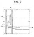
- Figure 2 is a partial sectional view illustrating a combination of a rotatable kneader, a rotatable arm, and a spring in the bread maker shown in Figure 1;
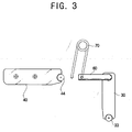
- Figures 3 and 4 illustrate operations of the rotatable kneader of Figure 2; and
- Figure 5 is a perspective view of a conventional bread maker.
-
- Hereinafter, embodiments of the present invention will be described in detail with reference to the attached drawings, wherein like reference numerals refer to the like elements throughout. The present invention may, however, be embodied in many different forms and should not be construed as being limited to the embodiments set forth herein; rather, these embodiments are provided so that the present disclosure will be thorough and complete, and will fully convey the concept of the invention to those skilled in the art.
- Figure 1 is a perspective view illustrating a bread maker according to an embodiment of the present invention. As shown therein, a bread maker according to the present invention includes a
main body 1 forming anoven compartment 10 and an electric component compartment (not shown), adoor 3 in the front of themain body 1 to open and close theoven compartment 10, and acontrol panel 5 in a front side of themain body 1 allowing a user to control the bread maker. - Inside the
oven compartment 10, upper andlower kneading drums oven compartment 10, between the upper and lower kneadingdrums baking tray 15 in which kneaded dough is contained. Inside the electric component compartment is a drum driving part (not shown) rotating the upper andlower kneading drums - At an upper inside portion of the
oven compartment 10, between the upper kneadingdrum 11 and thebaking tray 15, is akneader 50. - The
kneader 50 includes afixed kneader 40 and arotatable kneader 30 forming a pair. The fixed androtatable kneaders baking tray 15 to the upper kneadingdrum 111. - The
door 3 has apusher 20 on the inside surface thereof. Thepusher 20 pushes therotatable kneader 30 as thedoor 3 is closed, thereby returning therotatable kneader 30 from a downward rotated position (i.e., from a released position) to a kneading position. - As shown in Figures 2 through 4, the
fixed kneader 40 is attached to aside wall 9 of theoven compartment 10 and has afirst kneading roller 44 along a lengthwise direction thereof, which faces therotatable kneader 30 and contacts the mixing bag. Therotatable kneader 30 is attached to theside wall 9 of theoven compartment 10 and has asecond kneading roller 33 along a lengthwise direction thereof, which faces the fixed kneader 40 (Figure 4) and contacts the mixing bag. Hence, the rotatable andfixed kneaders - At an area in which the
rotatable kneader 30 is attached to theside wall 9 of theoven compartment 10, there are arotatable arm 60 extended and bent from one end of therotatable kneader 30, and aspring 70 elastically rotating therotatable kneader 30 to its kneading position. - The
rotatable arm 60 has a first end part connected to one end of therotatable kneader 30 that passes through theside wall 9 of theoven compartment 10, and a second end part extended from the first end part and coupled to thespring 70, which is connected to theside wall 9 of theoven compartment 10. - The
spring 70 is a toggle spring, and has a first end part coupled to theside wall 9 of theoven compartment 10 and a second end part coupled to therotatable arm 60. Thespring 70 elastically returns therotatable kneader 30, which moves as the mixing bag moves, to the kneading position when thedoor 3 is closed and elastically maintains therotatable kneader 30 at the released position when thedoor 3 is opened. - The
pusher 20 on the inside surface of thedoor 3 pushes therotatable kneader 30 when thedoor 3 is closed, thereby returning therotatable kneader 30 from a downward rotated position to the kneading position. Thepusher 20 pushes only enough for therotatable kneader 30 to be elastically returned to the kneading position by thespring 70. Thus, the user does not need to return therotatable kneader 30 to the kneading position. - The
pusher 20 may be made of a metal or heat-resistant plastic materials and has a size sufficient to return therotatable kneader 30 to the kneading position without damaging the mixing bag when thedoor 3 is closed. - Thus, the
rotatable kneader 30 is automatically returned to the kneading position by thepusher 20 on the inside surface of thedoor 3, thereby preventing the dough from being kneaded when therotatable kneader 30 has not been returned to the kneading position. - As described above, the embodiment of the present invention provides a bread maker with a pusher on the inside surface of a door, so that a rotatable kneader is automatically returned to a kneading position when the door is closed.
- Although a single embodiment of the present invention has been shown and described, it will be appreciated by those skilled in the art that changes may be made in this embodiment without departing from the principles and spirit of the invention, the scope of which is defined in the appended claims and their equivalents.
- The reader's attention is directed to all papers and documents which are filed concurrently with or previous to this specification in connection with this application and which are open to public inspection with this specification, and the contents of all such papers and documents are incorporated herein by reference.
- All of the features disclosed in this specification (including any accompanying claims, abstract and drawings), and/or all of the steps of any method or process so disclosed, may be combined in any combination, except combinations where at least some of such features and/or steps are mutually exclusive.
- Each feature disclosed in this specification (including any accompanying claims, abstract and drawings), may be replaced by alternative features serving the same, equivalent or similar purpose, unless expressly stated otherwise. Thus, unless expressly stated otherwise, each feature disclosed is one example only of a generic series of equivalent or similar features.
- The invention is not restricted to the details of the foregoing embodiment(s). The invention extends to any novel one, or any novel combination, of the features disclosed in this specification (including any accompanying claims, abstract and drawings), or to any novel one, or any novel combination, of the steps of any method or process so disclosed.
Claims (27)
- A bread maker having a main body (1) forming an oven compartment (10), a door (3) opening and closing the oven compartment (10), a fixed kneader (40) in the oven compartment (10) with a first kneading roller (44) contacting a mixing bag, and a rotatable kneader (30) in the oven compartment (10) with a second kneading roller (33), the rotatable kneader rotating between a kneading position at which the first kneading roller (44) and the second kneading roller (33) face each other with the mixing bag therebetween, and a released position at which the second kneading roller (33) is spaced apart from the first kneading roller (44), the bread maker comprising:a spring (70) having a first end attached to a side wall (9) of the oven compartment (10) and a second end coupled to the rotatable kneader (30), and elastically returning the rotatable kneader (30) to the kneading position as the door (3) is closed 'and elastically maintaining the rotatable kneader (30) at the released position when the door (3) is opened; anda pusher (20) on an inside surface of the door (3), pushing the rotatable (30) kneader from the released position to the kneading position as the door (3) is closed.
- The bread maker according to claim 1, further comprising a rotatable arm (60) connecting the spring (70) and the rotatable kneader (30).
- The bread maker according to claim 1 or claim 2, wherein the first kneading roller (44) extends lengthwise along the fixed kneader (40) and the second kneading roller (33) extends lengthwise along the rotatable kneader (30).
- The bread maker according to any preceding claim, wherein the pusher (20) is made of a metal or a heat-resistant plastic and has a size sufficient to automatically return the rotatable kneader (30) to the kneading position without damaging the mixing bag when the door (3) is closed.
- The bread maker according to claim 2, wherein the spring (70) is between the side wall (9) and the main body (1) and the rotatable arm (60) extends from the rotatable kneader (30) through the side wall (9) of the oven compartment (10) and is bent between an end connected to the spring (70) and an end extending through the side wall (9).
- The bread maker according to any preceding claim, further comprising an upper kneading drum (11) and a lower kneading drum (12) on which opposite ends of the mixing bag are attached and wound as the upper kneading drum (11) and the lower kneading drum (12) rotate in clockwise and counterclockwise directions.
- The bread maker according to claim 6, wherein the fixed kneader (40) and the rotatable kneader (30) knead dough in the mixing bag and prevent the dough from moving outside a baking tray (15) toward the upper kneading drum (11).
- The bread maker according to claim 6 or claim 7, wherein the mixing bag is kneaded by the fixed kneader (40) and the rotatable kneader (30) when the rotatable kneader (30) is in the kneading position as the mixing bag is wound and unwound on the upper kneading drum (11) and the lower kneading drum (12).
- A kneader for a bread maker having a main body (1) forming an oven compartment (10) and a door (3) opening and closing the oven compartment (10), the kneader comprising:a fixed kneader (40) in the oven compartment (10) having a first kneading roller (44);a rotatable kneader (30) in the oven compartment (10) having a second kneading roller (33) and being rotatable between a kneading position and a released position, the kneading position being a position at which the first kneading roller (44) and the second kneading roller (33) face one another to knead a mixing bag filled with bread ingredients placed therebetween, and the released position being a position at which the second kneading roller (33) is spaced apart from the first kneading roller (44); andan elastic member (70) having a first end attached to a side wall (9) of the oven compartment (10) and a second end attached to the rotatable kneader (30), and elastically maintaining the rotatable kneader (30) at the released position when the door (3) is opened and the rotatable kneader (30) is rotated away from the fixed kneader (40), and elastically returning the rotatable kneader (30) to the kneading position as the door (3) is closed.
- The kneader according to claim 9, further comprising a rotatable arm (60) connecting the elastic member (70) and the rotatable kneader (30).
- The kneader according to claim 9 or claim 10, wherein the first kneading roller (44) extends lengthwise along the fixed kneader (40) and the second kneading roller (33) extends lengthwise along the rotatable kneader (30).
- The kneader according to any one of claims 9-11, wherein the elastic member (70) is a toggle spring.
- The kneader according to claim 9, wherein a pusher (20) in an inner surface of the door (3) pushes the rotatable kneader (30) from the released position to the kneading position as the door (3) is closed.
- The kneader according to claim 13, wherein the pusher (20) is made of a metal or a heat-resistant plastic and has a size sufficient to automatically return the rotatable kneader (30) to the kneading position without damaging the mixing bag when the door (3) is closed.
- The kneader according to claim 10, wherein the elastic member (70) is between the side wall (9) and the main body (1) and the rotatable arm (60) extends from the rotatable kneader (30) through the side wall (9) of the oven compartment (10) and is bent between an end connected to the elastic member (70) and an end extending through the side wall (9).
- The kneader according to any one of claims 9-15, wherein the bread maker has an upper kneading drum (11) and a lower kneading drum (12) on which opposite ends of the mixing bag are attached and wound as the upper kneading drum (11) and the lower kneading drum (12) rotate in clockwise and counterclockwise directions.
- The kneader according to claim 16, wherein the fixed kneader (40) and the rotatable kneader (30) knead dough in the mixing bag and prevent the dough/from moving outside a baking tray (15) toward the upper kneading drum (11).
- The kneader according to claim 16 or claim 17, wherein the mixing bag is kneaded by the fixed kneader (40) and the rotatable kneader (30) when the rotatable kneader (30) is in the kneading position as the mixing bag is wound and unwound on the upper kneading drum (11) and the lower kneading drum (12).
- A kneading assembly for a bread maker having a main body (1) forming an oven compartment (10) and a door (3) opening and closing the oven compartment (10), the kneading assembly comprising:a fixed kneader (40) in the oven compartment (10);a rotatable kneader (30) in the oven compartment (10) adjacent the fixed kneader (40) and being rotatable between a kneading position and a released position, the kneading position being a position at which the rotatable kneader (30) and the fixed kneader (40) face one another to knead a mixing bag filled with bread ingredients placed therebetween, and the released position being a position at which the rotatable kneader (30) is rotated away from the fixed kneader (40);a pusher (20) on an inside surface of the door (3) to push the rotatable kneader (30) from the released position when the door (3) is opened to the kneading position as the door (3) is closed; andan elastic member (70) having a first end attached to a side wall (9) of the oven compartment (10) and a second end attached to the rotatable kneader (30), the elastic member (70) elastically maintaining the rotatable kneader (30) at the released position when the door (3) is opened and the rotatable kneader (30) is rotated away from the fixed kneader (40), and elastically returning the rotatable kneader (30) to the kneading position as the door (3) is closed and the pusher pushes the rotatable kneader (30) to the kneading position.
- The kneading assembly according to claim 19, further comprising a rotatable arm (60) connecting the elastic member (70) and the rotatable kneader (30).
- The kneading assembly according to claim 19 or claim 20, wherein a first kneading roller (44) extends lengthwise along the fixed kneader (40) and the second kneading roller (33) extends lengthwise along the rotatable kneader (30).
- The kneading assembly according to any one of claims 19-21, wherein the elastic member (70) is a toggle spring.
- The kneading assembly according to any one of claims 19-22, wherein the pusher (60) is made of a metal or a heat-resistant plastic and has a size sufficient to automatically return the rotatable kneader (30) to the kneading position without damaging the mixing bag when the door (3) is closed.
- The kneading assembly according to claim 20, wherein the elastic member (70) is between the side wall (9) and the main body (1) and the rotatable arm (60) extends from the rotatable kneader (30) through the side wall (9) of the oven compartment (10) and is bent between an end connected to the elastic member (60) and an end extending through the side wall (9).
- The kneading assembly according to any one of claims 19-24, wherein the bread maker has an upper kneading drum (11) and a lower kneading drum (12) on which opposite ends of the mixing bag are attached and wound as the upper kneading drum (11) and the lower kneading drum (12) rotate in clockwise and counterclockwise directions.
- The kneading assembly according to claim 25, wherein the fixed kneader (40) and the rotatable kneader (30) knead dough in the mixing bag and prevent the dough from moving outside a baking tray (15) toward the upper kneading drum (11).
- The kneading assembly according to claim 25 or claim 26, wherein the mixing bag is kneaded by the fixed kneader (40) and the rotatable kneader (30) when the rotatable kneader (30) is in the kneading position as the mixing bag is wound and unwound on the upper kneading drum (11) and the lower kneading drum (12).
Applications Claiming Priority (2)
| Application Number | Priority Date | Filing Date | Title |
|---|---|---|---|
| KR2002042767 | 2002-07-20 | ||
| KR10-2002-0042767A KR100471072B1 (en) | 2002-07-20 | 2002-07-20 | baking machine |
Publications (2)
| Publication Number | Publication Date |
|---|---|
| EP1382253A1 true EP1382253A1 (en) | 2004-01-21 |
| EP1382253B1 EP1382253B1 (en) | 2006-11-08 |
Family
ID=29775044
Family Applications (1)
| Application Number | Title | Priority Date | Filing Date |
|---|---|---|---|
| EP02258695A Expired - Lifetime EP1382253B1 (en) | 2002-07-20 | 2002-12-17 | Improvements in and relating to bread makers |
Country Status (5)
| Country | Link |
|---|---|
| US (1) | US6745670B2 (en) |
| EP (1) | EP1382253B1 (en) |
| JP (1) | JP3634838B2 (en) |
| KR (1) | KR100471072B1 (en) |
| DE (1) | DE60215928T2 (en) |
Families Citing this family (7)
| Publication number | Priority date | Publication date | Assignee | Title |
|---|---|---|---|---|
| KR20040096135A (en) * | 2003-05-07 | 2004-11-16 | 삼성전자주식회사 | Bake oven |
| KR20040096217A (en) * | 2003-05-07 | 2004-11-16 | 삼성전자주식회사 | Oven for baking bread |
| KR20040096137A (en) * | 2003-05-07 | 2004-11-16 | 삼성전자주식회사 | Baking machine and control method thereof |
| KR20040096218A (en) * | 2003-05-07 | 2004-11-16 | 삼성전자주식회사 | Bake oven |
| KR20040096215A (en) * | 2003-05-07 | 2004-11-16 | 삼성전자주식회사 | Oven for Baking Bread |
| CN108937624B (en) * | 2018-09-12 | 2025-04-18 | 中山市正梁电器制造有限公司 | Oven structure in which the baking utensils can be pulled out as the door opens and closes |
| CN110326634B (en) * | 2019-08-01 | 2020-07-14 | 北京鲲鹏神通科技有限公司 | Automatic pancake baking robot |
Citations (5)
| Publication number | Priority date | Publication date | Assignee | Title |
|---|---|---|---|---|
| WO1986003931A1 (en) * | 1984-12-27 | 1986-07-17 | Hedenteam A.G. | An apparatus for automatically making food products such as bread, cakes and the like |
| US4803086A (en) * | 1985-12-23 | 1989-02-07 | Heden-Team Aktiengesellschaft | Automatically making food products such as bread, cakes and the like |
| WO1992010100A1 (en) * | 1990-12-13 | 1992-06-25 | Heden-Team Ag | Automatic baking apparatus and mixbag therefor |
| WO1999025467A1 (en) * | 1997-11-17 | 1999-05-27 | Heden-Team Ag | Automatic baking apparatus and mixbag therefor |
| KR20020053646A (en) * | 2000-12-27 | 2002-07-05 | 윤종용 | Bake oven |
Family Cites Families (14)
| Publication number | Priority date | Publication date | Assignee | Title |
|---|---|---|---|---|
| SE8207438D0 (en) | 1982-12-28 | 1982-12-28 | Gunnar Hedenberg | KIT FOR MANUFACTURE OF FOOD PRODUCTS LIKE BREAD, COOKIES AND SIMILAR AND BAKING MACHINE FOR MANUFACTURE OF SAID PRODUCTS |
| US4550654A (en) * | 1983-04-01 | 1985-11-05 | Heden Team A.G. | Apparatus for automatic preparation of food products such as bread, cakes and the like |
| US4590850A (en) * | 1983-12-27 | 1986-05-27 | Heden Team A.G. | Apparatus for automatically making of food products such as bread, cakes and the like |
| JPH01300912A (en) | 1988-05-31 | 1989-12-05 | Sanyo Electric Co Ltd | Bread baking machine |
| JPH0261424A (en) | 1988-08-24 | 1990-03-01 | Matsushita Electric Ind Co Ltd | heating cooker |
| JPH02140518A (en) | 1988-11-21 | 1990-05-30 | Matsushita Electric Ind Co Ltd | Heat cooker with bread making function |
| US5146840A (en) * | 1989-11-22 | 1992-09-15 | Heden-Team Ag | Automatic baking apparatus and mixbag therefore |
| JPH0458555A (en) | 1990-06-28 | 1992-02-25 | Toshiba Corp | Power-on reset circuit |
| KR930003152B1 (en) | 1990-09-21 | 1993-04-22 | 삼성전자 주식회사 | Multinumbers enrollment method |
| KR930005280B1 (en) | 1990-10-31 | 1993-06-17 | 삼성전기 주식회사 | Machine for baking |
| JPH06327565A (en) | 1993-05-24 | 1994-11-29 | Matsushita Electric Ind Co Ltd | Automatic baking oven |
| JPH11346930A (en) | 1998-06-08 | 1999-12-21 | Matsushita Electric Ind Co Ltd | Automatic bread maker |
| KR200253646Y1 (en) | 1998-12-10 | 2001-12-13 | 황기연 | Pressure locking device for load switchgear with integrated bellows housing |
| KR100406308B1 (en) * | 2002-02-28 | 2003-11-19 | 삼성전자주식회사 | baking machine |
-
2002
- 2002-07-20 KR KR10-2002-0042767A patent/KR100471072B1/en not_active Expired - Fee Related
- 2002-11-28 JP JP2002346554A patent/JP3634838B2/en not_active Expired - Fee Related
- 2002-12-17 EP EP02258695A patent/EP1382253B1/en not_active Expired - Lifetime
- 2002-12-17 DE DE60215928T patent/DE60215928T2/en not_active Expired - Lifetime
-
2003
- 2003-06-11 US US10/458,658 patent/US6745670B2/en not_active Expired - Fee Related
Patent Citations (5)
| Publication number | Priority date | Publication date | Assignee | Title |
|---|---|---|---|---|
| WO1986003931A1 (en) * | 1984-12-27 | 1986-07-17 | Hedenteam A.G. | An apparatus for automatically making food products such as bread, cakes and the like |
| US4803086A (en) * | 1985-12-23 | 1989-02-07 | Heden-Team Aktiengesellschaft | Automatically making food products such as bread, cakes and the like |
| WO1992010100A1 (en) * | 1990-12-13 | 1992-06-25 | Heden-Team Ag | Automatic baking apparatus and mixbag therefor |
| WO1999025467A1 (en) * | 1997-11-17 | 1999-05-27 | Heden-Team Ag | Automatic baking apparatus and mixbag therefor |
| KR20020053646A (en) * | 2000-12-27 | 2002-07-05 | 윤종용 | Bake oven |
Non-Patent Citations (1)
| Title |
|---|
| DATABASE WPI Section Ch Week 200303, Derwent World Patents Index; Class D11, AN 2003-036595, XP002259437 * |
Also Published As
| Publication number | Publication date |
|---|---|
| US6745670B2 (en) | 2004-06-08 |
| JP3634838B2 (en) | 2005-03-30 |
| DE60215928T2 (en) | 2007-06-28 |
| US20040011214A1 (en) | 2004-01-22 |
| DE60215928D1 (en) | 2006-12-21 |
| KR100471072B1 (en) | 2005-03-10 |
| EP1382253B1 (en) | 2006-11-08 |
| JP2004049878A (en) | 2004-02-19 |
| KR20040008995A (en) | 2004-01-31 |
Similar Documents
| Publication | Publication Date | Title |
|---|---|---|
| EP1382253A1 (en) | Improvements in and relating to bread makers | |
| EP0823830B1 (en) | Microwave oven with improved door | |
| US11029035B2 (en) | Oven | |
| US6729227B2 (en) | Bread maker | |
| EP1382252B1 (en) | Improvements in and relating to bread makers | |
| JPH01184332A (en) | Cooking apparatus | |
| EP1474983A1 (en) | Improvements in and relating to bread makers | |
| US7360480B2 (en) | Bread maker | |
| US7275479B2 (en) | Bread maker | |
| EP1474976A1 (en) | Bread maker | |
| EP1477064A1 (en) | A bread maker | |
| EP1474981B1 (en) | Improvements in and relating to bread makers | |
| CN1235485C (en) | Bread making machine | |
| EP1474979B1 (en) | Bread maker | |
| EP1474982B1 (en) | A bread maker | |
| KR100456586B1 (en) | Baking machine | |
| EP1382257B1 (en) | Improvements in and relating to bread makers | |
| EP1475020A1 (en) | Bread maker | |
| EP1474978A1 (en) | Bread maker | |
| US20040221726A1 (en) | Bread maker |
Legal Events
| Date | Code | Title | Description |
|---|---|---|---|
| PUAI | Public reference made under article 153(3) epc to a published international application that has entered the european phase |
Free format text: ORIGINAL CODE: 0009012 |
|
| 17P | Request for examination filed |
Effective date: 20030113 |
|
| AK | Designated contracting states |
Kind code of ref document: A1 Designated state(s): AT BE BG CH CY CZ DE DK EE ES FI FR GB GR IE IT LI LU MC NL PT SE SI SK TR |
|
| AX | Request for extension of the european patent |
Extension state: AL LT LV MK RO |
|
| AKX | Designation fees paid |
Designated state(s): DE GB SE |
|
| 17Q | First examination report despatched |
Effective date: 20050504 |
|
| GRAP | Despatch of communication of intention to grant a patent |
Free format text: ORIGINAL CODE: EPIDOSNIGR1 |
|
| GRAS | Grant fee paid |
Free format text: ORIGINAL CODE: EPIDOSNIGR3 |
|
| GRAA | (expected) grant |
Free format text: ORIGINAL CODE: 0009210 |
|
| AK | Designated contracting states |
Kind code of ref document: B1 Designated state(s): DE GB SE |
|
| REG | Reference to a national code |
Ref country code: GB Ref legal event code: FG4D |
|
| REF | Corresponds to: |
Ref document number: 60215928 Country of ref document: DE Date of ref document: 20061221 Kind code of ref document: P |
|
| REG | Reference to a national code |
Ref country code: SE Ref legal event code: TRGR |
|
| PLBE | No opposition filed within time limit |
Free format text: ORIGINAL CODE: 0009261 |
|
| STAA | Information on the status of an ep patent application or granted ep patent |
Free format text: STATUS: NO OPPOSITION FILED WITHIN TIME LIMIT |
|
| 26N | No opposition filed |
Effective date: 20070809 |
|
| PGFP | Annual fee paid to national office [announced via postgrant information from national office to epo] |
Ref country code: GB Payment date: 20101215 Year of fee payment: 9 Ref country code: SE Payment date: 20101213 Year of fee payment: 9 |
|
| PGFP | Annual fee paid to national office [announced via postgrant information from national office to epo] |
Ref country code: DE Payment date: 20101215 Year of fee payment: 9 |
|
| REG | Reference to a national code |
Ref country code: SE Ref legal event code: EUG |
|
| GBPC | Gb: european patent ceased through non-payment of renewal fee |
Effective date: 20111217 |
|
| REG | Reference to a national code |
Ref country code: DE Ref legal event code: R119 Ref document number: 60215928 Country of ref document: DE Effective date: 20120703 |
|
| PG25 | Lapsed in a contracting state [announced via postgrant information from national office to epo] |
Ref country code: SE Free format text: LAPSE BECAUSE OF NON-PAYMENT OF DUE FEES Effective date: 20111218 Ref country code: DE Free format text: LAPSE BECAUSE OF NON-PAYMENT OF DUE FEES Effective date: 20120703 Ref country code: GB Free format text: LAPSE BECAUSE OF NON-PAYMENT OF DUE FEES Effective date: 20111217 |