EP1381230A1 - Satellite broadcast receiving tuner with compensation of cable loss - Google Patents
Satellite broadcast receiving tuner with compensation of cable loss Download PDFInfo
- Publication number
- EP1381230A1 EP1381230A1 EP03015278A EP03015278A EP1381230A1 EP 1381230 A1 EP1381230 A1 EP 1381230A1 EP 03015278 A EP03015278 A EP 03015278A EP 03015278 A EP03015278 A EP 03015278A EP 1381230 A1 EP1381230 A1 EP 1381230A1
- Authority
- EP
- European Patent Office
- Prior art keywords
- satellite
- filter
- amplifier
- broadcast receiving
- switch
- Prior art date
- Legal status (The legal status is an assumption and is not a legal conclusion. Google has not performed a legal analysis and makes no representation as to the accuracy of the status listed.)
- Granted
Links
- 238000010276 construction Methods 0.000 description 8
- 238000010586 diagram Methods 0.000 description 4
- 230000006835 compression Effects 0.000 description 3
- 238000007906 compression Methods 0.000 description 3
- 230000003247 decreasing effect Effects 0.000 description 3
- 229920006395 saturated elastomer Polymers 0.000 description 2
- 238000006243 chemical reaction Methods 0.000 description 1
Images
Classifications
-
- H—ELECTRICITY
- H03—ELECTRONIC CIRCUITRY
- H03J—TUNING RESONANT CIRCUITS; SELECTING RESONANT CIRCUITS
- H03J5/00—Discontinuous tuning; Selecting predetermined frequencies; Selecting frequency bands with or without continuous tuning in one or more of the bands, e.g. push-button tuning, turret tuner
- H03J5/24—Discontinuous tuning; Selecting predetermined frequencies; Selecting frequency bands with or without continuous tuning in one or more of the bands, e.g. push-button tuning, turret tuner with a number of separate pretuned tuning circuits or separate tuning elements selectively brought into circuit, e.g. for waveband selection or for television channel selection
- H03J5/242—Discontinuous tuning; Selecting predetermined frequencies; Selecting frequency bands with or without continuous tuning in one or more of the bands, e.g. push-button tuning, turret tuner with a number of separate pretuned tuning circuits or separate tuning elements selectively brought into circuit, e.g. for waveband selection or for television channel selection used exclusively for band selection
- H03J5/244—Discontinuous tuning; Selecting predetermined frequencies; Selecting frequency bands with or without continuous tuning in one or more of the bands, e.g. push-button tuning, turret tuner with a number of separate pretuned tuning circuits or separate tuning elements selectively brought into circuit, e.g. for waveband selection or for television channel selection used exclusively for band selection using electronic means
Definitions
- the present invention relates to a satellite broadcast receiving tuner that tunes in a satellite-broadcasting signal that undergoes conversion into an intermediate frequency band by an outdoor downconverter.
- a known satellite broadcast receiving tuner (hereinafter, referred to as a BS tuner) is described with reference to Fig. 4.
- the satellite-broadcasting signal having a plurality of channels is converted into an intermediate frequency band of approximately 0.95 to 2.15 GHz by an outdoor downconverter (not shown), is brought indoors via a cable (not shown), and is fed via an input terminal (IN) of the BS tuner to a band-pass filter 21.
- the band-pass filter 21 has a passband of the 0.95 to 2.15 GHz.
- the band-pass filter 21 is connected to a first-stage amplifier 22, which is connected to a distributor 23.
- One output terminal of the distributor 23 is connected to a second-stage amplifier 24.
- the second-stage amplifier 24 includes a variable gain amplifier and is gain-controlled in accordance with an AGC (Automatic Gain Control) voltage.
- the satellite-broadcasting signal amplified by the second-stage amplifier 24 is fed into an IQ demodulator 25.
- a carrier whose frequency is equal to that of the satellite-broadcasting signal to be received is fed from an oscillator (not shown) to the IQ demodulator 25 where the satellite-broadcasting signal to be received is mixed with the carrier into two baseband signals (I signal and Q signal) whose phases intersect each other.
- the satellite-broadcasting signal to be received is tuned in by the IQ demodulator 25.
- the AGC voltage is produced based on the demodulated baseband signal.
- the filter may include a high-pass filter.
- the switch, the amplifier, and the IQ demodulator may be integrated in an integrated circuit, which further includes terminals for allowing the filter to be connected in parallel with the switch.
- a BS tuner of the present invention will be described with reference to Fig. 1.
- a satellite broadcasting signal having a plurality of channels is frequency-converted into an intermediate frequency band of approximately 0.95 to 2.15 GH z by an outdoor downconverter (not shown), is brought indoors via a cable (not shown), and is fed via an input terminal (IN) of the BS tuner into the band-pass filter 1.
- the band-pass filter 1 has a passband of the 0.95 to 2.15 GHz.
- the band-pass filter 1 is connected to a first-stage amplifier 2, which is connected to a distributor 3.
- One output terminal of the distributor 3 is connected to a variable attenuator 4.
- the variable attenuator 4 is controlled in accordance with the level of the satellite-broadcasting signal to be received.
- a switch 6 At the subsequent stage of the variable attenuator 4 is disposed a switch 6, which is connected in parallel with a filter 5.
- the filter 5 includes a band-pass filter or a high-pass filter so as to permit passing of a satellite-broadcasting signal whose frequency is higher than or equal to a predetermined frequency of the intermediate frequency band.
- the passband thereof can be shifted so as to be able to accommodate the frequency of the satellite broadcasting signal to be received in a range that is higher than or equal to the predetermined frequency.
- the switch 6 is controlled so as to be normally ON (closed) and OFF (open) when the satellite-broadcasting signal whose frequency is higher than or equal to the predetermined frequency is received.
- a second-stage amplifier (subsequent-stage amplifier) 7 is disposed at the subsequent stage of the switch 6 and the filter 5.
- An IQ demodulator 8 is disposed at the subsequent stage of the second-stage amplifier 7.
- the satellite broadcasting signal amplified by the second-stage amplifier 7 is fed into the IQ demodulator 8.
- a carrier whose frequency is equal to that of the satellite broadcasting signal to be received is fed from an oscillator (not shown) to the IQ demodulator 8 where the satellite broadcasting signal to be received is mixed with the carrier to be converted into two baseband signals (I signal and Q signal) whose phases intersect each other. Therefore, the satellite-broadcasting signal to be received is tuned in by the IQ demodulator 25.
- the variable attenuator 4 is controlled by an AGC voltage produced based on the demodulated baseband signal.
- the satellite-broadcasting signal produced from the other terminal of the distributor 3 is fed into another indoor BS tuner.
- the level of the satellite broadcasting signal in the band of 0.95 to 2.15 GHz fed to the input terminal (IN) of the BS tuner is high in lower frequency (Lf) channels and low in higher frequency (Hf) channels. This is due to not only that the signal loss occurring in the cable has frequency characteristics but also that the frequency characteristics of a booster amplifier or a distributor provided in the middle are added.
- the switch 6 is turned off, allowing the satellite broadcasting signal produced from the variable attenuator 4 to be fed via the filter 5 to the second-stage amplifier 7.
- This causes the filter 5 to attenuate a high-level satellite-broadcasting signal in the lower frequency (Lf) region.
- the level thereof is decreased.
- the gain compression does not occur. Therefore, when the low-level higher frequency region satellite-broadcasting signal is demodulated, the insufficient amount of the baseband signal level does not occur.
- the switch 6 When the lower frequency region satellite-broadcasting signal is received, the switch 6 is turned on. In addition, when the level of the satellite-broadcasting signal fed into the input terminal (IN) is determined to be substantially uniform over the above entire intermediate frequency band, the switch 6 is turned on and connecting to the filter 5 is not required.
- the switch 6 is disposed between the distributor 3 and the second-stage amplifier 7.
- a node of one output terminal of the distributor 3 and the switch 6 is connected to a filter connection terminal 10c provided in the integrated circuit 10.
- a node of the switch 6 and the second-stage amplifier 7 is connected to a filter connection terminal 10d provided in the integrated circuit 10. Connecting the filter 5 between the two nodes 10c and 10d causes the filter 5 to be connected in parallel with the switch 6.
- the IQ demodulator 8 is disposed next to the second-stage amplifier 7.
- the variable attenuator 4 in Fig. 1 is not included in the integrated circuit 10.
- the second-stage amplifier 7 includes a variable gain amplifier which is gain-controlled by the AGC voltage.
Landscapes
- Input Circuits Of Receivers And Coupling Of Receivers And Audio Equipment (AREA)
- Two-Way Televisions, Distribution Of Moving Picture Or The Like (AREA)
- Circuits Of Receivers In General (AREA)
Abstract
Description
- The present invention relates to a satellite broadcast receiving tuner that tunes in a satellite-broadcasting signal that undergoes conversion into an intermediate frequency band by an outdoor downconverter.
- A known satellite broadcast receiving tuner (hereinafter, referred to as a BS tuner) is described with reference to Fig. 4. The satellite-broadcasting signal having a plurality of channels is converted into an intermediate frequency band of approximately 0.95 to 2.15 GHz by an outdoor downconverter (not shown), is brought indoors via a cable (not shown), and is fed via an input terminal (IN) of the BS tuner to a band-
pass filter 21. The band-pass filter 21 has a passband of the 0.95 to 2.15 GHz. - The band-
pass filter 21 is connected to a first-stage amplifier 22, which is connected to adistributor 23. One output terminal of thedistributor 23 is connected to a second-stage amplifier 24. The second-stage amplifier 24 includes a variable gain amplifier and is gain-controlled in accordance with an AGC (Automatic Gain Control) voltage. The satellite-broadcasting signal amplified by the second-stage amplifier 24 is fed into anIQ demodulator 25. A carrier whose frequency is equal to that of the satellite-broadcasting signal to be received is fed from an oscillator (not shown) to theIQ demodulator 25 where the satellite-broadcasting signal to be received is mixed with the carrier into two baseband signals (I signal and Q signal) whose phases intersect each other. Thus, the satellite-broadcasting signal to be received is tuned in by theIQ demodulator 25. The AGC voltage is produced based on the demodulated baseband signal. - The satellite-broadcasting signal output from the other terminal of the
distributor 23 is fed into another indoor BS tuner. - In the above construction, the longer the distance between the outdoor downconverter and the indoor BS tuner is, the larger the signal loss due to the cable. Accordingly, a booster amplifier is inserted in the middle of the cable in order to compensate the loss. In addition, when the signal is fed into another BS tuner, another distributor is inserted. In this state, the frequency characteristics of the booster amplifier and the distributor are added to the frequency characteristics of the cable. Compared to the level of the satellite-broadcasting signal in a lower frequency region of the intermediate frequency band fed into the BS tuner, the level of the signal in a higher frequency region is significantly decreased. The difference between the levels of the two frequency regions may be several tens of dB.
- When the low-level satellite-broadcasting signal in the higher frequency region is received in such a state, the high-level satellite-broadcasting signal in the lower frequency region causes the second-
stage amplifier 24 to be saturated, causing gain compression. This causes a problem in which the insufficient amount of the demodulated baseband signal level occurs since the satellite-broadcasting signal in the higher frequency region cannot be sufficiently amplified. - To solve this problem, it is only required that a band-pass filter whose passband is capable of being shifted over the entire intermediate frequency band is provided between the
distributor 23 and the second-stage amplifier 24. However, constructing a band-pass filter whose passband is capable of being shifted over such a wide range of the passband is difficult. - Accordingly, it is an object of the present invention to provide a BS tuner with a simple construction that prevents an amplifier from failing to sufficiently amplify a low-level satellite-broadcasting signal due to gain compression that a high-level satellite-broadcasting signal causes the amplifier to generate when the low-level satellite-broadcasting signal is received.
- To this end, there is provided a satellite broadcast receiving tuner including an amplifier for amplifying a plurality of satellite broadcasting signals in an intermediate frequency band, the plurality of satellite broadcasting signals fed through a cable from an outdoor downconverter, an IQ demodulator disposed at the subsequent stage of the amplifier, the IQ demodulator demodulating the satellite broadcasting signals, a switch, and a filter for allowing the satellite broadcasting signals in a higher frequency region of the intermediate frequency band to pass. In the satellite broadcast receiving tuner, the satellite broadcasting signals are fed into the amplifier through one of the switch and the filter.
- The filter may include a high-pass filter.
- The filter may include a band-pass filter whose passband can be shifted.
- Alternatively, the switch, the amplifier, and the IQ demodulator may be integrated in an integrated circuit, which further includes terminals for allowing the filter to be connected in parallel with the switch.
- Embodiments of the present invention will now be described, by way of example, with reference to the accompanying diagrammatic drawings, in which:
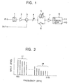
- Fig. 1 is a circuit diagram showing a construction of a satellite broadcast receiving tuner of the present invention;
- Fig. 2 is a diagram showing the level of a satellite-broadcasting signal fed into the satellite broadcast receiving tuner of the present invention;
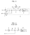
- Fig. 3 is a circuit diagram showing another construction of the satellite broadcast receiving tuner of the present invention; and
- Fig. 4 is a circuit diagram showing a construction of a known satellite broadcast receiving tuner.
-
- A BS tuner of the present invention will be described with reference to Fig. 1. A satellite broadcasting signal having a plurality of channels is frequency-converted into an intermediate frequency band of approximately 0.95 to 2.15 GHz by an outdoor downconverter (not shown), is brought indoors via a cable (not shown), and is fed via an input terminal (IN) of the BS tuner into the band-pass filter 1. The band-pass filter 1 has a passband of the 0.95 to 2.15 GHz.
- The band-pass filter 1 is connected to a first-
stage amplifier 2, which is connected to adistributor 3. One output terminal of thedistributor 3 is connected to a variable attenuator 4. The variable attenuator 4 is controlled in accordance with the level of the satellite-broadcasting signal to be received. At the subsequent stage of the variable attenuator 4 is disposed aswitch 6, which is connected in parallel with afilter 5. Thefilter 5 includes a band-pass filter or a high-pass filter so as to permit passing of a satellite-broadcasting signal whose frequency is higher than or equal to a predetermined frequency of the intermediate frequency band. - When the
filter 5 includes, for example, the band-pass filter, the passband thereof can be shifted so as to be able to accommodate the frequency of the satellite broadcasting signal to be received in a range that is higher than or equal to the predetermined frequency. Theswitch 6 is controlled so as to be normally ON (closed) and OFF (open) when the satellite-broadcasting signal whose frequency is higher than or equal to the predetermined frequency is received. - A second-stage amplifier (subsequent-stage amplifier) 7 is disposed at the subsequent stage of the
switch 6 and thefilter 5. AnIQ demodulator 8 is disposed at the subsequent stage of the second-stage amplifier 7. The satellite broadcasting signal amplified by the second-stage amplifier 7 is fed into theIQ demodulator 8. A carrier whose frequency is equal to that of the satellite broadcasting signal to be received is fed from an oscillator (not shown) to theIQ demodulator 8 where the satellite broadcasting signal to be received is mixed with the carrier to be converted into two baseband signals (I signal and Q signal) whose phases intersect each other. Therefore, the satellite-broadcasting signal to be received is tuned in by theIQ demodulator 25. The variable attenuator 4 is controlled by an AGC voltage produced based on the demodulated baseband signal. - The satellite-broadcasting signal produced from the other terminal of the
distributor 3 is fed into another indoor BS tuner. - As shown in Fig. 2, in the above construction, generally, the level of the satellite broadcasting signal in the band of 0.95 to 2.15 GHz fed to the input terminal (IN) of the BS tuner is high in lower frequency (Lf) channels and low in higher frequency (Hf) channels. This is due to not only that the signal loss occurring in the cable has frequency characteristics but also that the frequency characteristics of a booster amplifier or a distributor provided in the middle are added.
- Accordingly, when the satellite broadcasting signal in the higher frequency (Hf) region higher than or equal to the predetermined frequency, the region in which the level thereof is decreased, is received, the
switch 6 is turned off, allowing the satellite broadcasting signal produced from the variable attenuator 4 to be fed via thefilter 5 to the second-stage amplifier 7. This causes thefilter 5 to attenuate a high-level satellite-broadcasting signal in the lower frequency (Lf) region. Before the signal is fed into the second-stage amplifier 7, the level thereof is decreased. As a result of this, since the lower frequency region satellite-broadcasting signal does not cause the second-stage amplifier 7 to be saturated, the gain compression does not occur. Therefore, when the low-level higher frequency region satellite-broadcasting signal is demodulated, the insufficient amount of the baseband signal level does not occur. - When the lower frequency region satellite-broadcasting signal is received, the
switch 6 is turned on. In addition, when the level of the satellite-broadcasting signal fed into the input terminal (IN) is determined to be substantially uniform over the above entire intermediate frequency band, theswitch 6 is turned on and connecting to thefilter 5 is not required. - Referring to Fig. 3, the components following the first-
stage amplifier 2 among the construction shown in Fig. 1 are built in an integrated circuit (IC) 10, which is provided with aninput terminal 10a and anoutput terminal 10b to be connected to thefilter 5. The satellite-broadcasting signal fed to the input terminal of the BS tuner is input via the band-pass filter 1 to theinput terminal 10a. The other output terminal of thedistributor 3 is connected to theoutput terminal 10b of theintegrated circuit 10. A band-pass filter 11 provided outside of theintegrated circuit 10 is connected to theoutput terminal 10b Thus, the output from thedistributor 3 is fed via the band-pass filter 11 to an output terminal OUT of the BS tuner. - The
switch 6 is disposed between thedistributor 3 and the second-stage amplifier 7. A node of one output terminal of thedistributor 3 and theswitch 6 is connected to afilter connection terminal 10c provided in theintegrated circuit 10. Likewise, a node of theswitch 6 and the second-stage amplifier 7 is connected to afilter connection terminal 10d provided in theintegrated circuit 10. Connecting thefilter 5 between the twonodes filter 5 to be connected in parallel with theswitch 6. TheIQ demodulator 8 is disposed next to the second-stage amplifier 7. In this construction, the variable attenuator 4 in Fig. 1 is not included in theintegrated circuit 10. Instead, the second-stage amplifier 7 includes a variable gain amplifier which is gain-controlled by the AGC voltage.
Claims (4)
- A satellite broadcast receiving tuner comprising:an amplifier for amplifying a plurality of satellite broadcasting signals in an intermediate frequency band, the plurality of satellite broadcasting signals fed through a cable from an outdoor downconverter;an IQ demodulator disposed at the subsequent stage of the amplifier, the IQ demodulator demodulating the satellite broadcasting signals;a switch; anda filter for allowing the satellite broadcasting signals in a higher frequency region of the intermediate frequency band to pass, wherein the satellite broadcasting signals are fed into the amplifier through one of the switch and the filter.
- A satellite broadcast receiving tuner according to Claim 1, wherein the filter includes a high-pass filter.
- A satellite broadcast receiving tuner according to Claim 1, wherein the filter includes a band-pass filter whose passband can be shifted.
- A satellite broadcast receiving tuner according to one of Claims 1 to 3, wherein:the switch, the amplifier, and the IQ demodulator are integrated in an integrated circuit; andthe integrated circuit further includes terminals for allowing the filter to be connected in parallel with the switch.
Applications Claiming Priority (2)
| Application Number | Priority Date | Filing Date | Title |
|---|---|---|---|
| JP2002199383A JP2004048123A (en) | 2002-07-09 | 2002-07-09 | Tuner for receiving satellite broadcast |
| JP2002199383 | 2002-07-09 |
Publications (2)
| Publication Number | Publication Date |
|---|---|
| EP1381230A1 true EP1381230A1 (en) | 2004-01-14 |
| EP1381230B1 EP1381230B1 (en) | 2005-01-19 |
Family
ID=29728426
Family Applications (1)
| Application Number | Title | Priority Date | Filing Date |
|---|---|---|---|
| EP20030015278 Expired - Lifetime EP1381230B1 (en) | 2002-07-09 | 2003-07-07 | Satellite broadcast receiving tuner with compensation of cable loss |
Country Status (3)
| Country | Link |
|---|---|
| EP (1) | EP1381230B1 (en) |
| JP (1) | JP2004048123A (en) |
| DE (1) | DE60300276T2 (en) |
Citations (3)
| Publication number | Priority date | Publication date | Assignee | Title |
|---|---|---|---|---|
| EP0929149A1 (en) * | 1998-01-12 | 1999-07-14 | Alps Electric Co., Ltd. | Receiver for data transmission |
| EP1073199A2 (en) * | 1999-07-29 | 2001-01-31 | Alps Electric Co., Ltd. | Television tuner that generates no interfering signal |
| EP1104103A1 (en) * | 1999-11-25 | 2001-05-30 | Alps Electric Co., Ltd. | Switchable band filter |
-
2002
- 2002-07-09 JP JP2002199383A patent/JP2004048123A/en not_active Withdrawn
-
2003
- 2003-07-07 DE DE60300276T patent/DE60300276T2/en not_active Expired - Fee Related
- 2003-07-07 EP EP20030015278 patent/EP1381230B1/en not_active Expired - Lifetime
Patent Citations (3)
| Publication number | Priority date | Publication date | Assignee | Title |
|---|---|---|---|---|
| EP0929149A1 (en) * | 1998-01-12 | 1999-07-14 | Alps Electric Co., Ltd. | Receiver for data transmission |
| EP1073199A2 (en) * | 1999-07-29 | 2001-01-31 | Alps Electric Co., Ltd. | Television tuner that generates no interfering signal |
| EP1104103A1 (en) * | 1999-11-25 | 2001-05-30 | Alps Electric Co., Ltd. | Switchable band filter |
Also Published As
| Publication number | Publication date |
|---|---|
| EP1381230B1 (en) | 2005-01-19 |
| DE60300276T2 (en) | 2006-01-12 |
| JP2004048123A (en) | 2004-02-12 |
| DE60300276D1 (en) | 2005-02-24 |
Similar Documents
| Publication | Publication Date | Title |
|---|---|---|
| US6307599B1 (en) | Analog-digital broadcast shared receiving tuner | |
| CN1098558C (en) | Automatic Gain Control Circuit Device for Tuner | |
| EP0117654B2 (en) | Multistage amplifier | |
| EP1013092B1 (en) | Direct-conversion tuner integrated circuit for direct broadcast satellite television | |
| US5014349A (en) | Television tuner for common use in BS/UV | |
| JPH08154061A (en) | Broadcast signal receiver | |
| GB2323727A (en) | Gain control in a TV tuner with control applied to an attenuator and an amplifier | |
| US7212796B2 (en) | Antenna unit and receiving circuit | |
| JP4235560B2 (en) | Automatic gain control for tuners | |
| US8427586B2 (en) | Tuner comprising an IF filter with a controllable damping stage and receiver comprising a respective tuner | |
| EP1225697A2 (en) | Method and circuit for avoiding band interference wave in receiver | |
| EP1383248A2 (en) | Superheterodyne receiver | |
| US7088975B1 (en) | Automatic gain control system and method using multiple local AGC loops | |
| EP1381230B1 (en) | Satellite broadcast receiving tuner with compensation of cable loss | |
| EP1383318A2 (en) | Television tuner in which influence from analog signals is suppressed when receiving digital signals | |
| EP1197080A1 (en) | Method and apparatus for providing dual automatic gain control delay settings in a television receiver | |
| US6501513B1 (en) | Television signal receiving tuner | |
| KR100311808B1 (en) | Digital Tuner Improves Adjacent Channel Rejection Characteristics of Low Symbol Signals | |
| US5303410A (en) | Signal strength meter circuit for radio receiver | |
| KR100384463B1 (en) | Loop through circuit of digital ground wave tuner | |
| JP2003298438A (en) | CS tuner | |
| EP1005155B1 (en) | Television signal receiving tuner | |
| KR0133242Y1 (en) | Satellite broadcast tuner complementing strong-electric field | |
| JPS6211539B2 (en) | ||
| MXPA98001898A (en) | Shared receiver of analogue-digi transmission |
Legal Events
| Date | Code | Title | Description |
|---|---|---|---|
| PUAI | Public reference made under article 153(3) epc to a published international application that has entered the european phase |
Free format text: ORIGINAL CODE: 0009012 |
|
| AK | Designated contracting states |
Kind code of ref document: A1 Designated state(s): AT BE BG CH CY CZ DE DK EE ES FI FR GB GR HU IE IT LI LU MC NL PT RO SE SI SK TR |
|
| AX | Request for extension of the european patent |
Extension state: AL LT LV MK |
|
| 17P | Request for examination filed |
Effective date: 20040105 |
|
| 17Q | First examination report despatched |
Effective date: 20040216 |
|
| GRAP | Despatch of communication of intention to grant a patent |
Free format text: ORIGINAL CODE: EPIDOSNIGR1 |
|
| AKX | Designation fees paid |
Designated state(s): DE FR GB |
|
| GRAS | Grant fee paid |
Free format text: ORIGINAL CODE: EPIDOSNIGR3 |
|
| GRAA | (expected) grant |
Free format text: ORIGINAL CODE: 0009210 |
|
| AK | Designated contracting states |
Kind code of ref document: B1 Designated state(s): DE FR GB |
|
| REG | Reference to a national code |
Ref country code: GB Ref legal event code: FG4D |
|
| REG | Reference to a national code |
Ref country code: IE Ref legal event code: FG4D |
|
| REF | Corresponds to: |
Ref document number: 60300276 Country of ref document: DE Date of ref document: 20050224 Kind code of ref document: P |
|
| PLBE | No opposition filed within time limit |
Free format text: ORIGINAL CODE: 0009261 |
|
| STAA | Information on the status of an ep patent application or granted ep patent |
Free format text: STATUS: NO OPPOSITION FILED WITHIN TIME LIMIT |
|
| ET | Fr: translation filed | ||
| 26N | No opposition filed |
Effective date: 20051020 |
|
| PGFP | Annual fee paid to national office [announced via postgrant information from national office to epo] |
Ref country code: FR Payment date: 20060724 Year of fee payment: 4 |
|
| PGFP | Annual fee paid to national office [announced via postgrant information from national office to epo] |
Ref country code: DE Payment date: 20060925 Year of fee payment: 4 |
|
| GBPC | Gb: european patent ceased through non-payment of renewal fee |
Effective date: 20070707 |
|
| PG25 | Lapsed in a contracting state [announced via postgrant information from national office to epo] |
Ref country code: DE Free format text: LAPSE BECAUSE OF NON-PAYMENT OF DUE FEES Effective date: 20080201 |
|
| PG25 | Lapsed in a contracting state [announced via postgrant information from national office to epo] |
Ref country code: GB Free format text: LAPSE BECAUSE OF NON-PAYMENT OF DUE FEES Effective date: 20070707 |
|
| REG | Reference to a national code |
Ref country code: FR Ref legal event code: ST Effective date: 20080331 |
|
| PG25 | Lapsed in a contracting state [announced via postgrant information from national office to epo] |
Ref country code: FR Free format text: LAPSE BECAUSE OF NON-PAYMENT OF DUE FEES Effective date: 20070731 |