EP1381225A2 - Scene change detector and method thereof - Google Patents
Scene change detector and method thereof Download PDFInfo
- Publication number
- EP1381225A2 EP1381225A2 EP03011638A EP03011638A EP1381225A2 EP 1381225 A2 EP1381225 A2 EP 1381225A2 EP 03011638 A EP03011638 A EP 03011638A EP 03011638 A EP03011638 A EP 03011638A EP 1381225 A2 EP1381225 A2 EP 1381225A2
- Authority
- EP
- European Patent Office
- Prior art keywords
- scene change
- signal
- detector according
- change detector
- pixels
- Prior art date
- Legal status (The legal status is an assumption and is not a legal conclusion. Google has not performed a legal analysis and makes no representation as to the accuracy of the status listed.)
- Withdrawn
Links
Images


Classifications
-
- H—ELECTRICITY
- H04—ELECTRIC COMMUNICATION TECHNIQUE
- H04N—PICTORIAL COMMUNICATION, e.g. TELEVISION
- H04N5/00—Details of television systems
- H04N5/14—Picture signal circuitry for video frequency region
- H04N5/147—Scene change detection
-
- H—ELECTRICITY
- H04—ELECTRIC COMMUNICATION TECHNIQUE
- H04N—PICTORIAL COMMUNICATION, e.g. TELEVISION
- H04N9/00—Details of colour television systems
- H04N9/64—Circuits for processing colour signals
- H04N9/646—Circuits for processing colour signals for image enhancement, e.g. vertical detail restoration, cross-colour elimination, contour correction, chrominance trapping filters
Definitions
- the present invention relates to a scene change detector and a method thereof, and more particularly, to a scene change detector and a method of detecting a scene change between motion pictures by using co-relation information between histograms with respect to color signals of chroma or luminance.
- a scene change represents that a motion picture changes from one scene to another scene in consecutive scenes (screen pictures) after the one scene is finished.
- the scene change is generally divided into several modes: a fade-out and fade-in mode that a certain scene is gradually disappeared and another scene is slowly shown, an overlap mode that two certain scenes are overlapped slowly from different directions for a certain time interval, and a simple scene change mode.
- a scene change detector is an apparatus detecting the scene change of the motion picture and can be applied to digital TVs, a computer-based image processing system, and an MPEG signal processing system.
- an interframe coding technique using motion prediction and compensation is adapted to compress data that is closely related on an axis of time.
- a frequency of redundancy of same image data is low, thereby causing an amount of the data to be increased. Therefore, when the MPEG signal processing system is performed without reflecting special picture effects like the scene change, a rate of bit utilization is lowered and a quality of the motion picture deteriorates, thus it is necessary to perform the scene change detection before signal processing of the motion picture.
- US Patent No. 6,049,363 entitled “Object detection method and system for scene change analysis in TV and IR data” discloses a pixel difference method based on information of edges of two frames for scene change detection.
- US Patent No. 5,032,905 entitled “Accurate detection of a drastic change between successive pictures” discloses a frame difference method applied between two frames for scene change detection.
- US patent No. 5,835,663 entitled “Apparatus for recording image data representative of cuts in a video signal” discloses another method of a scene change detection in that a histogram with respect to a chroma color signal of each sub block is obtained after two frames are divided into sub blocks, wherein correlation information is calculated to be statistically processed through a total comparison of the sub blocks.
- the conventional scene change detectors and the methods thereof cannot provide an effective method to improve the quality of the moving picture by detecting Tl ("Title Insertion"), that is a subtitle displayed on the moving picture, or PIP ("Picture in Picture”), that is, another picture displayed in the moving picture to be considered together with the scene change.
- Tl Transmission Insertion
- PIP Picture in Picture
- the present invention has been made to overcome the above and/ other problems of the related art. Accordingly, it is the aspect of the present invention to provide a scene change detector and a method thereof which can be used when motion information in an image frame is not significant such as a case of improving a contrast of a picture in the image frame.
- Another aspect of the present invention is to provide a scene change detector and method capable of improving a quality of a picture when there is Tl (Title Insertion) or PIP (Picture In Picture) by considering a scene change.
- a scene change detector includes first and second histogram detection units individually calculating first and second histograms with respect to predetermined input first and second color signals, a cross correlation coefficient calculation unit calculating a correlation value between the first and second histograms calculated from the first and the second histogram detection units respectively, and a decision unit outputting a scene change signal by comparing the correlation value with a predetermined threshold.
- the scene change detector further includes first and second frame buffers storing two image frame data to detect the scene change, respectively, and first and second color space conversion units converting the image frame data stored in the first and the second frame buffers into the predetermined first and second color signals and outputting the predetermined first and second color signals to the first and the second histogram detection units, respectively.
- the predetermined first and second color signals are luminance color signals or chroma color signals. It is possible that the first and the second histogram detection units quantize the respective ones of the input color signals to a predetermined signal band, calculate the number of pixels having the same value of the quantized input color signal with respect to all pixels in a predetermined frame, and calculate the first and the second histograms by standardizing the calculated number. It is possible that the decision unit outputs the scene change signal when the correlation value is less than the predetermined threshold which is in a range of 0.9 to 0.95.
- a scene change detector includes first and second histogram detection units individually calculating histograms with respect to predetermined input first and second color signals, first and second average/maximum calculation units individually calculating average values and maximum values from the first and the second histograms calculated at the first and the second histogram detection units, respectively, a comparison unit outputting an average signal by comparing a first difference between the first and the second average values calculated from the first and the second average/maximum calculation units with a predetermined first threshold, respectively, and a maximum signal by comparing a second difference between the first and the second maximum values calculated from the first and the second average/maximum calculation units with a predetermined second threshold, first and second filters individually outputting first and second histograms having suppressed respective peak values by filtering the first and the second histograms, a cross correlation coefficient calculation unit calculating a correlation value between the filtered first and second histograms, and a decision unit outputting a scene change signal by comparing the correlation value with a pre
- the scene change detector further includes first and second frame buffers individually storing two image frame data to detect the scene change signal, and first and second color space conversion units to convert the image frame data stored in the first and the second frame buffers into the predetermined first and the second color signals and output the converted first and the second color signals to the first and the second histogram detection units, respectively.
- the predetermined first and the second color signals are luminance color signals or chroma color signals.
- the first and the second histogram detection units quantize the respective input color signals to a predetermined signal band, calculate the number of pixels having the same value of quantized color signal from the quantized input color signals with respect to all pixels in a predetermined frame, and calculate the first and the second histograms by standardizing the calculated number, respectively.
- the decision unit outputs the scene change signal when the correlation value is less than the predetermined third threshold which is in a range of 0.9 to 0.95.
- the comparison unit outputs the average signal when the difference between the first and the second average values are greater than the predetermined first threshold, and outputs the maximum signal when the difference between the first and the second maximum values are greater than the second threshold.
- the decision unit receives the average signal and the maximum signal, and outputs the Tl signal and the PIP signal when the scene change signal is greater than the predetermined first threshold.
- a method of scene detecting includes calculating first and second histograms with respect to predetermined input first and second color signals, calculating a correlation value between the first and the second histograms, and outputting a scene change signal when the correlation value is less than a predetermined threshold.
- the method of scene detecting further includes individually storing two image frame data to detect the scene change signal and converting the image frame data into the predetermined first and second color signals, respectively.
- a method of scene detecting includes individually calculating first and second histograms with respect to input predetermined first and second color signals, calculating first and second average values and first and second maximum values from the first and the second histograms, outputting an average signal when a first difference between the calculated first and second average values is greater than a predetermined first threshold, and outputting a maximum signal when a second difference between the first and the second maximum values is greater than a predetermined second threshold, filtering the first and the second histograms to limit peak values and individually output the filtered first and second histograms, calculating a correlation value between the filtered first and second histograms, outputting a scene change signal when the correlation value is less than a predetermined third threshold, inputting the average signal and the maximum signal, and outputting a Tl signal or a PIP signal when the correlation value is greater than the predetermined third threshold.
- the method of scene detecting of the present invention further includes individually storing two image frame data to detect the scene change signal and converting the image frame data into the predetermined first and second color signals.
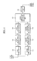
- FIG. 1 is a block diagram showing a scene change detector according to an embodiment of the present invention.
- the scene change detector includes a first frame buffer 100, a first color space conversion unit 102, a first histogram detection unit 104, a second frame buffer 110, a second color space conversion unit 112, a second histogram detection unit 114, a cross correlation coefficient calculator 120, and a decision unit 130.
- the first frame buffer and the second frame buffer 100 and 110 individually store two image frame data having a predetermined temporal interval to detect a scene change from input video stream data.
- the first and second color space conversion units 102 and 112 individually convert respective color spaces of the image frame data stored in the first and the second frame buffers 100 and 110 into respective color signals.
- the first and the second histogram detection units 104 and 114 individually calculate first and second histograms from the color signals converted at the first and the second color space conversion unit 102 and 112.
- the cross correlation coefficient calculator 120 calculates a correlation value C between the calculated first and second histograms, and the decision unit 130 compares the calculated correlation value C with a predetermined threshold and outputs a scene change signal.
- FIG. 2 is a flow chart showing an operation method of the scene change detector of FIG. 1.
- two image frame data having a predetermined temporal interval are respectively stored into the first and the second frame buffers 100 and 110 to detect a scene change from input video stream data in operation S150.
- the color spaces of the image frame data stored in the first and the second frame buffers 100 and 110 are converted at the first and the second color space conversion units 102 and 112 into chroma (or luminance) color signals in operation S152.
- the frame image data stored into the first and the second frame buffers 100 and 102 can have the color spaces, such as RGB, YIQ, YUV, YcbCr, or HLS based on a utility environment.
- These color spaces are converted into chroma (or luminance) color signals by using appropriate equations. For example, a calculation of the chroma (or luminance) color signal from an RGB color signal can be operated using the following equation 1.
- a, b, and c are conversion coefficients.
- a 0.29900
- b 0.58700
- c 0.1140. They are typical conversion coefficients used for JPEG compressing.
- the first and the second histogram detection units 104 and 114 individually calculate the histograms from the chroma (or luminance) color signals converted at the first and the second color space conversion units 102 and 112 in operation S154 .
- one of the histograms calculated at the first histogram calculation unit 104 is a first histogram
- the other one of the histograms calculated at the second histogram calculation unit 114 is a second histogram.
- the method of calculating the first and the second histograms is as follows.
- the chroma (or luminance) color signals converted from the respective color spaces by the first and the second color space conversion units 102 and 112 are quantized to a predetermined signal band, such as 0 ⁇ 100 scales, 0 ⁇ 127 scales, or 0-255 scales, and each histogram is calculated to count the number of values having the same value with respect to a selected local window or entire pixels of an image frame or field. After a maximum value is searched in the histogram, the histogram is calculated by normalizing to allow the maximum value to have a certain value (for example, 100).
- FIGS. 3A and 3B are views of the first and the second histograms calculated based on the above method.
- the shown histograms have the signal band of 0 ⁇ 255 and the maximum value of 100.
- an axis X is the signal band of 0 ⁇ 255
- an axis Y corresponding to each axis X is a counted value of the number of the pixels having the same value.
- the cross correlation coefficient calculation unit 120 calculates the correlation value C by using the following equation between the first histogram calculated at the first histogram calculation unit 104 and the second histogram calculated at the second histogram calculation unit 114 in operation S156.
- x i is a predetermined value on the axis X of the first histogram calculated at the first histogram calculation unit 104
- y i is a predetermined value on the axis X of the second histogram calculated at the second histogram calculation unit 114.
- x is an average value of individual histogram counters of the first histogram
- y is an average value of individual histogram counters of the second histogram.
- the correlation value C calculated by the equation 2 has a value between -1 and 1.
- the correlation value C is -1.
- the correlation value C is close to 1.
- the correlation value C is 1, it is determined that the first histogram and the second histogram are the same.
- the decision unit 130 creates a scene change signal C sc by comparing the correlation value C calculated at the equation 2 with the predetermined threshold. In other words, when the correlation value C is less than the predetermined threshold, it can be regarded that the scene change is generated.
- An experimentally calculated threshold is 0.9 to 0.95. Therefore, when the correlation value C is less than 0.9 to 0.95, it is determined that there exists the scene change, thus the scene change signal C sc is output as 1. When the correlation value C is greater than 0.9 to 0.95, the scene change signal C sc is 0.
- FIG. 4 is a block diagram showing another scene change detector according to another embodiment of the present invention.
- the scene change detector includes a first frame buffer 200, a first color space conversion unit 202, a first histogram detection unit 204, a first filter 206, a first average/maximum calculation unit 208, a second frame buffer 210, a second color space conversion unit 212, a second histogram detection unit 214, a second filter 216, a second average/maximum calculation unit 218, a cross correlation coefficient calculation unit 220, a comparison unit 222, and a decision unit 230.
- the scene change detector has more additional blocks, such as the first and the second filters 206 and 216, the first and the second average/maximum calculation units 208 and 218, and the comparison unit 222 than those of the scene change detector of FIG. 1.
- These additional blocks are used to detect mainly a picture-in-picture (PIP) signal or a title insertion (Tl) signal.
- PIP picture-in-picture
- Tl title insertion
- Respective functions of the first and the second frame buffers 200 and 210, the first and the second color space conversion units 202 and 212, the first and the second histogram detection units 204 and 214, and the cross correlation coefficient calculation unit 220 are the same as those of the scene change detector of FIG. 1. Therefore, hereinbelow, functions of the additional blocks will be described.
- the first and the second average/maximum calculation units 208 and 218 individually calculate an average value and a maximum value with respect to first and second histograms calculated at the first and the second histogram detection units 204 and 214.
- the average value and the maximum value calculated from the first histogram at the first average/maximum calculation unit 208 are a first average value and a first maximum value, respectively, and the average value and the maximum value calculated from the second histogram at the second average/maximum calculation unit 208 are a second average value and a second maximum value, respectively.
- the first and the second average values and the first and the second maximum values calculated at the first and the second average/maximum calculation units 208 and 218 are transmitted to the comparison unit 222.
- the comparison unit 222 calculates an average signal C mean and a maximum signal C max based on the following equations.
- ⁇ S mean S mean ( T - ⁇ T ) - S mean ( T )
- ⁇ T is a predetermined temporal interval
- S max (T - ⁇ T ) and S max (T) are the maximum values of the first and the second histograms, respectively.
- the case of the average values of the first and the second histograms is the same as described above.
- the average signal C mean and the maximum signal C max calculated at the comparison unit 230 are transmitted to the decision unit 230.
- the first and the second filters 206 and 216 reduce a peak value of the respective histograms formed by the Tl signal or the PIP signal by using a linear or a non-linear filter.
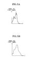
- FIG. 5A shows a histogram formed by the Tl or PIP signal
- FIG. 5B shows another histogram formed by the signals passing through the first filter 206 or the second filter 216.
- the peak value of the signals is limited when the signals pass through the first and the second filters 206 and 216.
- the scene change signal Csc is prevented from being unconditionally output.
- the first and the second filters 206 and 216 are a linear low pass filter or a non-linear medial filter.
- the following equation is an example of an output histogram value with respect to an input histogram value calculated by using a 5-Tab median filter.
- F out ( i ) Median [ F input ( i - 2), F input ( i -1), F input ( i ), F input ( i + 1), F input ( i + 2)]
- F input (i) is the input histogram value
- F out (i) is the output histogram value.
- a median operator is a filtering method to take a medium value by rearranging given histogram values by their magnitudes. Once a histogram is finished its filtering, the maximum value is set, and the maximum value is standardized to a predetermined value (for example, 100).
- the standardized histogram is transmitted to the cross correlation coefficient calculation unit 220.
- the cross correlation coefficient calculation unit 220 calculates the correlation value C by using the equation 2 explained above.
- the calculated correlation value C is transmitted to the decision unit 230.
- the decision unit 230 creates the scene change signal Csc and the PIP (picture in picture)/TI (title insertion) signals CTI/P based on the following signal by using the correlation value C, the average signal C mean and the maximum signal C max .
- the correlation value C when the correlation value C is less than a threshold, it is a case of a general scene change.
- the scene change signal Csc is output as 1.
- C max or C mean is 1 there is a significant change in preceding and following images, and at the same time, the correlation value C is greater than the threshold, then it is determined that the Tl or PIP exists.
- the scene change unrelated to the movement in the image frame can be detected by using correlation information between histograms of chroma or luminance color signal. Moreover, the quality of the picture can be more effectively improved since the scene change by the Tl or PIP and the general scene change can be separated from each other.
Landscapes
- Engineering & Computer Science (AREA)
- Multimedia (AREA)
- Signal Processing (AREA)
- Compression Or Coding Systems Of Tv Signals (AREA)
- Image Analysis (AREA)
- Color Television Systems (AREA)
- Processing Of Color Television Signals (AREA)
Abstract
Description

Claims (50)
- A scene change detector comprising:first and second histogram detection units computing histograms from input first and second color signals, respectively;i a cross correlation coefficient calculation unit calculating a correlation value between the first and second histograms computed by the first and second histogram detection units, respectively; anda decision unit outputting a scene change signal by comparing the correlation value with a threshold.
- The scene change detector according to claim 1, further comprising:first and second frame buffers storing two image frame data, respectively, to detect a scene change; andfirst and second color space conversion units converting the image frame data stored in the first and second frame buffers into the first and second color signals to be outputted to the first and second histogram detection units, respectively.
- The scene change detector according to claim 2, wherein the first and second color signals are luminance color signals.
- The scene change detector according to claim 2, wherein the first and second color signals are chroma color signals.
- The scene change detector according to claim 1, wherein the first and second histogram detection units quantize the input first and second color signals to signal bands, respectively, each calculate the number of pixels having the same values of the quantized first and second color signals with respect to all pixels in a predetermined frame region, and calculate the first and second histograms by standardizing the calculated respective numbers, respectively.
- The scene change detector according to claim 1, wherein the decision unit outputs the scene change signal when the correlation value is less than the threshold.
- The scene change detector according to claim 6, wherein the threshold is in a range of 0.9 to 0.95 inclusive.
- A scene change detector comprising:first and second histogram detection units calculating first and second histograms from input first and second color signals, respectively;first and second average/maximum calculation units calculating average values and maximum values from the first and second histograms calculated at the first and second histogram detection units, respectively;a comparison unit outputting an average signal by comparing a first difference between the first and second average values calculated from the first and second average/maximum calculation units, respectively, with a first threshold, and a maximum signal by comparing a second difference between the first and second maximum values calculated from the first and second average/maximum calculation units, respectively, with a second threshold;first and second filters filtering the first and second histograms to output the filtered first and second histograms having suppressed peak values, respectively;a cross correlation coefficient calculation unit calculating a correlation value between the filtered first and second histograms; anda decision unit outputting a scene change signal by comparing the correlation value with a third threshold, and a Tl (Title Insertion) or PIP (Picture In Picture) signal based on the scene change signal and the average signal and the maximum signal output from the comparison unit .
- The scene change detector according to claim 8, further comprisingfirst and second frame buffers storing two image frame data to detect a scene change; andfirst and second color space conversion units converting the image frame data stored in the first and second frame buffers into the first and second color signals and outputting the first and second color signals to the first and second histogram detection units, respectively.
- The scene change detector according to claim 9, wherein the first and second color signals are luminance color signals.
- The scene change detector according to claim 9, wherein the first and second color signals are chroma color signals.
- The scene change detector according to claim 8, wherein the first and second histogram calculation units quantize the input first and second color signals to respective signal bands, each calculate the number of pixels having the same values of the quantized first and second color signals with respect to all pixels in respective frame regions, and calculate the first and second histograms by standardizing the calculated respective numbers, respectively.
- The scene change detector according to claim 8, wherein the decision unit outputs the scene change signal when the correlation value is less than the third threshold.
- The scene change detector according to claim 8, wherein the third threshold is in a range of 0.9 to 0.95 inclusive.
- The scene change detector according to claim 13, wherein the comparison unit outputs the average signal when the difference between the first and second average values is greater than the first threshold, and the maximum signal when the difference between the first and second maximum values is greater than the second threshold.
- The scene change detector according to claim 8, wherein the decision unit receives the average signal and the maximum signal and outputs the Tl or PIP signal when the scene change signal is greater than the first threshold.
- A method of detecting a scene change, the method comprising:computing first and second histograms with respect to input first and second color signals, respectively;calculating a correlation value between the first and second histograms; andoutputting a scene change signal when the correlation value is less than a threshold.
- The method according to claim 17, wherein the computing of the first and second histograms comprises:storing two image frame data separately to detect the scene change; andconverting the stored two frame data into the first and second color signals.
- A method of detecting a scene change, the method comprising:computing first and second histograms with respect to input first and second color signals;calculating first and second average values and first and second maximum values from the first and second histograms, respectively;outputting an average signal when a first difference between the calculated first and second average values is greater than a first threshold, and outputting a maximum signal when a second difference between the first and second maximum values is greater than a second threshold;filtering the first and the second histograms to output the filtered first and second histograms having suppressed peak values;calculating a correlation value between the filtered first and second histograms; andoutputting a scene change signal when the correlation value is less than a third threshold, and outputting a Tl or PIP signal when the correlation value is greater than the third threshold with the average and maximum signals being inputted thereto.
- The method according to claim 19, wherein the computing of the first and second histograms comprises:storing two image frame data separately to detect the scene change; andconverting the stored two image frame data into the first and second color signals.
- A scene change detector comprising:first and second histogram detection units each computing each number of respective pixels having the same value from first and second video signals, respectively; anda decision unit outputting a scene change signal in accordance with the number of the pixels of each of the first and second video signals.
- The scene change detector according to claim 21, wherein the first and second video signals have a temporal interval in video stream data.
- The scene change detector according to claim 21, wherein the first and second video signals comprise:one of an RGB type signal, a YIQ type signal, a YUV type signal, a YcbCr type signal, and an HLS type signal.
- The scene change detector according to claim 21, further comprising:first and second memories storing the first and second video signals, respectively.
- The scene change detector according to claim 21, further comprising:first and second memories storing first and second image frame/field data of video stream data corresponding to the first and second video signals, respectively.
- The scene change detector according to claim 25, further comprising:first and second color space conversion units converting the stored first and second image frame/field data of video stream data into the first and second video signals, respectively.
- The scene change detector according to claim 21, wherein the first and second histogram detection units compute first and second histograms representing respective numbers of the respective pixels having the same value from first and second video signals, respectively.
- The scene change detector according to claim 27, wherein each of the first and second histograms comprises:first numbers each representing the number of the pixels having the same value; andsecond numbers each representing the number of the pixels having different values.
- The scene change detector according to claim 28, wherein decision unit outputs the scene change signal in accordance with the first numbers and the second numbers.
- The scene change detector according to claim 27, further comprising:a cross correlation coefficient calculation unit calculating a correlation value between the first and the second histograms, wherein the decision unit outputs the scene change signal upon comparing the correlation value with a threshold.
- The scene change detector according to claim 21, further comprising:first and second filters filtering the respective numbers of the pixels having the same value to suppress one of the respective numbers of the pixels which is greater than a peak value, respectively.
- The scene change detector according to claim 21, wherein the first and second histogram detection unit computes another number of the respective pixels having different values, respectively, and the decision unit outputs the scene change signal in accordance with the number and the another number of the pixels of each of the first and second video signals.
- The scene change detector according to claim 21, wherein the first and second histogram detection units compute another number of the respective pixels having different values, respectively, the number and the another number of the pixels are normalized in first and second ranges, respectively, and the decision unit outputs the scene change signal in accordance with the normalized number and the normalized another number of the pixels.
- The scene change detector according to claim 21, wherein the first and second histogram detection units compute another number of the respective pixels having different values, and the detector further comprises:first and second average/maximum calculation units calculating first and second average signals and first and second maximum signals from the number of the pixels, respectively.
- The scene change detector according to claim 34, wherein the decision unit outputs the scene change signal in accordance with the first and second average signals and the first and second maximum signals of the first and second average/maximum calculation units.
- The scene change detector according to claim 34, wherein the number and the another number of the pixels are normalized in first and second ranges, respectively.
- The scene change detector according to claim 36, wherein the first range is N times of a scale between 1 and 100 inclusive, and N is a positive number.
- The scene change detector according to claim 36, wherein the second range is N times of a scale between 0 and 255, inclusive, and N is a positive number.
- The scene change detector according to claim 34, wherein the number of the pixels has a maximum number of 100 when the number of the pixels is in a scale between 1 and 100 inclusive.
- The scene change detector according to claim 34, wherein the another number of the pixels has a maximum number of 255 when the number of the pixels is in a scale between 0 and 255 inclusive.
- The scene change detector according to claim 21, wherein the respective pixels have one of a second number of different values, and the detector further comprises:a cross correlation coefficient calculation unit calculating a correlation value between the first and second video signals in the respective numbers of the respective pixels corresponding to the second number of different values.
- The scene change detector according to claim 41, wherein the decision unit outputs the scene change signal upon comparing the correlation value with a threshold.
- The scene change detector according to claim 42, wherein the scene change signal represents that there is a scene change between the first and second video signals, when the correlation value is less than a threshold.
- The scene change detector according to claim 42, wherein the scene change signal represents that there is a title insertion signal or a picture-in-picture signal in the first and second video signals, when the correlation value is greater than a threshold.
- The scene change detector according to claim 21, wherein the respective pixels are a portion of or all pixels forming a frame or field corresponding the first and second video signals, respectively.
- A scene change detector comprising:first and second histogram detection units forming correlation information between histograms of a chroma or luminance color signal and detecting a scene change unrelated to a movement in an image frame from the formed correlation information; anda decision unit outputting a scene change signal in accordance with the detected scene change.
- A method in a scene change detector, the method comprising:computing respective numbers of respective pixels having the same value from first and second video signals, respectively; andoutputting a scene change signal in accordance with the respective numbers of the pixels of the first and second video signals.
- The method of claim 47, wherein the respective numbers comprises the second number of the pixels having different values, and the computing of the number of the respective pixels comprises:calculating a correlation value between the first and second video signals in the respective numbers of the respective pixels corresponding to the second number of different values.
- The method of claim 47, wherein the outputting of the scene change signal comprises:comparing the correlation value with a threshold to output the scene change signal representing one of a scene change and a title insertion or picture-in-picture signal in the first and second video signals.
- A method in a scene change detector, the method comprising:detecting a scene change unrelated to a movement in an image frame by using correlation information between histograms of a chroma or luminance color signal; andoutputting a scene change signal in accordance with the detected scene change.
Applications Claiming Priority (2)
| Application Number | Priority Date | Filing Date | Title |
|---|---|---|---|
| KR1020020039579A KR20040006065A (en) | 2002-07-09 | 2002-07-09 | Scene change detector and method thereof |
| KR2002039579 | 2002-07-09 |
Publications (2)
| Publication Number | Publication Date |
|---|---|
| EP1381225A2 true EP1381225A2 (en) | 2004-01-14 |
| EP1381225A3 EP1381225A3 (en) | 2004-05-06 |
Family
ID=29728781
Family Applications (1)
| Application Number | Title | Priority Date | Filing Date |
|---|---|---|---|
| EP20030011638 Withdrawn EP1381225A3 (en) | 2002-07-09 | 2003-05-22 | Scene change detector and method thereof |
Country Status (5)
| Country | Link |
|---|---|
| US (1) | US20040008284A1 (en) |
| EP (1) | EP1381225A3 (en) |
| JP (2) | JP3810392B2 (en) |
| KR (1) | KR20040006065A (en) |
| CN (2) | CN1984237A (en) |
Cited By (3)
| Publication number | Priority date | Publication date | Assignee | Title |
|---|---|---|---|---|
| EP1865463A3 (en) * | 2006-06-07 | 2009-08-19 | Ericsson AB | Temporal noise analysis of a video signal |
| CN102932582A (en) * | 2012-10-26 | 2013-02-13 | 华为技术有限公司 | Method and device for realizing motion detection |
| CN104811586A (en) * | 2015-04-24 | 2015-07-29 | 福建星网锐捷安防科技有限公司 | Scene change video intelligent analyzing method, device, network camera and monitoring system |
Families Citing this family (35)
| Publication number | Priority date | Publication date | Assignee | Title |
|---|---|---|---|---|
| US7219352B2 (en) * | 2002-04-15 | 2007-05-15 | Microsoft Corporation | Methods and apparatuses for facilitating processing of interlaced video images for progressive video displays |
| KR20040008067A (en) * | 2002-07-15 | 2004-01-28 | 삼성전자주식회사 | Image enhancing circuit using corelation between frames and method therefor |
| US7643675B2 (en) * | 2003-08-01 | 2010-01-05 | Microsoft Corporation | Strategies for processing image information using a color information data structure |
| US7030690B2 (en) * | 2004-02-12 | 2006-04-18 | Honeywell International, Inc. | Operational amplifier with selectable performance characteristics |
| KR100612494B1 (en) * | 2004-06-07 | 2006-08-14 | 삼성전자주식회사 | Device and method for adjusting color saturation |
| JP3912548B2 (en) * | 2004-11-04 | 2007-05-09 | 船井電機株式会社 | Optical disk device |
| CN100391232C (en) * | 2005-01-07 | 2008-05-28 | 智辉研发股份有限公司 | digital image flash scene detection and elimination method |
| US7880815B2 (en) * | 2005-01-10 | 2011-02-01 | Mavs Lab, Inc. | Method for detecting and eliminating flash scene in digital video |
| US7532256B2 (en) * | 2005-01-25 | 2009-05-12 | Teresis Media Management | Methods and apparatus for detecting scenes in a video medium |
| CN101119726B (en) | 2005-02-16 | 2011-02-02 | 麦仁斯有限公司 | Pharmaceutical composition for the treatment or prevention of diseases involving obesity, diabetes, metabolic syndrome, neuro-degenerative diseases and mitochondria dysfunction diseases |
| JP2007060169A (en) | 2005-08-23 | 2007-03-08 | Sony Corp | Image processing apparatus, image display apparatus, and image processing method |
| JP4419933B2 (en) | 2005-08-26 | 2010-02-24 | ソニー株式会社 | Image processing apparatus, image display apparatus, and image processing method |
| CN100435556C (en) * | 2005-10-31 | 2008-11-19 | 台湾新力国际股份有限公司 | camera system |
| CN101072342B (en) * | 2006-07-01 | 2010-08-11 | 腾讯科技(深圳)有限公司 | Situation switching detection method and its detection system |
| KR100812041B1 (en) * | 2006-07-19 | 2008-03-10 | 주식회사 대우일렉트로닉스 | Automatic Indexing Method Using Improved Scene Transition Detection Method |
| JP4849339B2 (en) * | 2007-03-30 | 2012-01-11 | ソニー株式会社 | Information processing apparatus and method |
| KR101359920B1 (en) | 2007-04-03 | 2014-02-12 | 포항공과대학교 산학협력단 | Driving apparatus for display device, display device including the same and driving method of display device |
| US20080247665A1 (en) * | 2007-04-04 | 2008-10-09 | Silicon Integrated Systems Corp. | Method and apparatus for dynamic contrast enhancement |
| US20100088232A1 (en) * | 2008-03-21 | 2010-04-08 | Brian Gale | Verification monitor for critical test result delivery systems |
| US20100104018A1 (en) * | 2008-08-11 | 2010-04-29 | New York University | System, method and computer-accessible medium for providing body signature recognition |
| JP4609559B2 (en) * | 2008-09-02 | 2011-01-12 | ソニー株式会社 | Filter device, image correction circuit, image display device, and image correction method |
| KR101149522B1 (en) * | 2008-12-15 | 2012-05-25 | 한국전자통신연구원 | Apparatus and method for detecting scene change |
| CN102333174A (en) * | 2011-09-02 | 2012-01-25 | 深圳市万兴软件有限公司 | Video image processing method and device for the same |
| US8971645B1 (en) * | 2012-05-18 | 2015-03-03 | Google Inc. | Video categorization using heterogeneous signals |
| US9195892B2 (en) * | 2013-03-15 | 2015-11-24 | Arris Technology, Inc. | System for and method of detecting strobe using spatial features in video frames |
| CN104184925A (en) * | 2014-09-11 | 2014-12-03 | 刘鹏 | Video scene change detection method |
| US20170004859A1 (en) * | 2015-06-30 | 2017-01-05 | Coursera, Inc. | User created textbook |
| JP6557592B2 (en) * | 2015-12-15 | 2019-08-07 | 日本放送協会 | Video scene division apparatus and video scene division program |
| KR20180135075A (en) | 2016-07-14 | 2018-12-19 | 삼성전자주식회사 | Chroma intra prediction method and apparatus therefor |
| CN106358029B (en) * | 2016-10-18 | 2019-05-03 | 北京字节跳动科技有限公司 | A kind of method of video image processing and device |
| CN109327655B (en) * | 2017-07-31 | 2020-12-22 | 展讯通信(上海)有限公司 | Continuous autofocus method and system |
| CN108171153B (en) * | 2017-12-26 | 2021-10-01 | 深圳Tcl新技术有限公司 | Scene change detection method, device, and computer-readable storage medium |
| CN109977738B (en) * | 2017-12-28 | 2023-07-25 | 深圳Tcl新技术有限公司 | A video scene segmentation judgment method, intelligent terminal and storage medium |
| JP7266179B2 (en) * | 2018-02-28 | 2023-04-28 | パナソニックIpマネジメント株式会社 | Image processing device and imaging device |
| US12079274B2 (en) | 2018-10-16 | 2024-09-03 | NBCUniversal Studios LLC | Systems and methods for identifying scene changes in video files |
Family Cites Families (14)
| Publication number | Priority date | Publication date | Assignee | Title |
|---|---|---|---|---|
| JPH05236458A (en) * | 1992-02-20 | 1993-09-10 | Toshiba Corp | Video processing device |
| US5719643A (en) * | 1993-08-10 | 1998-02-17 | Kokusai Denshin Denwa Kabushiki Kaisha | Scene cut frame detector and scene cut frame group detector |
| US5805733A (en) * | 1994-12-12 | 1998-09-08 | Apple Computer, Inc. | Method and system for detecting scenes and summarizing video sequences |
| JPH09130732A (en) * | 1995-11-01 | 1997-05-16 | Matsushita Electric Ind Co Ltd | Scene change detection method and moving image editing apparatus |
| US6219382B1 (en) * | 1996-11-25 | 2001-04-17 | Matsushita Electric Industrial Co., Ltd. | Method and apparatus for locating a caption-added frame in a moving picture signal |
| JP3730740B2 (en) * | 1997-02-24 | 2006-01-05 | 株式会社日立製作所 | Parallel job multiple scheduling method |
| KR100249826B1 (en) * | 1997-12-01 | 2000-03-15 | 정선종 | Digital moving image data automatic dividing device and method |
| WO1999041684A1 (en) * | 1998-02-13 | 1999-08-19 | Fast Tv | Processing and delivery of audio-video information |
| AU4239200A (en) * | 1999-04-16 | 2000-11-02 | Avid Technology, Inc. | Apparatus and method for generating and displaying histograms of color images for color correction |
| JP2000324499A (en) * | 1999-05-14 | 2000-11-24 | Fujitsu Ltd | Image processing apparatus and scene change detection method |
| KR100698106B1 (en) * | 2000-03-07 | 2007-03-26 | 엘지전자 주식회사 | Hierarchical Mixed Scene Change Detection Method in MPEG Compressed Video Environment |
| FR2807902B1 (en) * | 2000-04-17 | 2002-10-25 | Thomson Multimedia Sa | METHOD FOR DETECTING CHANGE OF PLANE IN SUCCESSION OF VIDEO IMAGES |
| US6995805B1 (en) * | 2000-09-29 | 2006-02-07 | Sonic Solutions | Method and system for scene change detection |
| KR20020040503A (en) * | 2000-11-24 | 2002-05-30 | 구자홍 | Shot detecting method of video stream |
-
2002
- 2002-07-09 KR KR1020020039579A patent/KR20040006065A/en not_active Ceased
-
2003
- 2003-05-22 EP EP20030011638 patent/EP1381225A3/en not_active Withdrawn
- 2003-07-03 US US10/611,953 patent/US20040008284A1/en not_active Abandoned
- 2003-07-09 JP JP2003272531A patent/JP3810392B2/en not_active Expired - Fee Related
- 2003-07-09 CN CNA2006101631868A patent/CN1984237A/en active Pending
- 2003-07-09 CN CNA031475086A patent/CN1471306A/en active Pending
-
2006
- 2006-04-14 JP JP2006112547A patent/JP2006254486A/en not_active Withdrawn
Cited By (6)
| Publication number | Priority date | Publication date | Assignee | Title |
|---|---|---|---|---|
| EP1865463A3 (en) * | 2006-06-07 | 2009-08-19 | Ericsson AB | Temporal noise analysis of a video signal |
| CN102932582A (en) * | 2012-10-26 | 2013-02-13 | 华为技术有限公司 | Method and device for realizing motion detection |
| CN102932582B (en) * | 2012-10-26 | 2015-05-27 | 华为技术有限公司 | Method and device for realizing motion detection |
| US9142032B2 (en) | 2012-10-26 | 2015-09-22 | Huawei Technologies Co., Ltd. | Method and apparatus for implementing motion detection |
| CN104811586A (en) * | 2015-04-24 | 2015-07-29 | 福建星网锐捷安防科技有限公司 | Scene change video intelligent analyzing method, device, network camera and monitoring system |
| CN104811586B (en) * | 2015-04-24 | 2018-01-16 | 福建星网物联信息系统有限公司 | Scene change Intelligent video analysis method, device, web camera and monitoring system |
Also Published As
| Publication number | Publication date |
|---|---|
| CN1984237A (en) | 2007-06-20 |
| KR20040006065A (en) | 2004-01-24 |
| EP1381225A3 (en) | 2004-05-06 |
| JP3810392B2 (en) | 2006-08-16 |
| CN1471306A (en) | 2004-01-28 |
| JP2004040808A (en) | 2004-02-05 |
| US20040008284A1 (en) | 2004-01-15 |
| JP2006254486A (en) | 2006-09-21 |
Similar Documents
| Publication | Publication Date | Title |
|---|---|---|
| EP1381225A2 (en) | Scene change detector and method thereof | |
| US8902990B2 (en) | Block error compensating apparatus of image frame and method thereof | |
| EP1711019B1 (en) | Motion compensated temporal filtering for noise reduction pre-processing of digital video data | |
| US8160161B2 (en) | Method and apparatus for performing motion compensated temporal filtering in video encoding | |
| US8233060B2 (en) | Image data processing apparatus, image data processing method, and program | |
| US20100165207A1 (en) | Apparatus and method of motion detection for temporal mosquito noise reduction in video sequences | |
| US6904096B2 (en) | Video data processing device and video data processing method | |
| US5589884A (en) | Adaptive quantization controlled by scene change detection | |
| US20080095232A1 (en) | Method and apparatus for implementing b-picture scene changes | |
| EP1506525B1 (en) | System for and method of sharpness enhancement for coded digital video | |
| US8023765B2 (en) | Block noise removal device | |
| US7734110B2 (en) | Method for filtering the noise of a digital image sequence | |
| KR20040069208A (en) | Improving temporal consistency in video sharpness enhancement | |
| GB2390951A (en) | Identifying telecine signals by comparing an inter-field motion pattern with a reference pattern | |
| US8184721B2 (en) | Recursive filtering of a video image | |
| JP4500112B2 (en) | Image feature amount detection device, image quality improvement device, display device, and receiver | |
| JP3334384B2 (en) | Picture prediction coding method |
Legal Events
| Date | Code | Title | Description |
|---|---|---|---|
| PUAI | Public reference made under article 153(3) epc to a published international application that has entered the european phase |
Free format text: ORIGINAL CODE: 0009012 |
|
| 17P | Request for examination filed |
Effective date: 20030522 |
|
| AK | Designated contracting states |
Kind code of ref document: A2 Designated state(s): AT BE BG CH CY CZ DE DK EE ES FI FR GB GR HU IE IT LI LU MC NL PT RO SE SI SK TR |
|
| AX | Request for extension of the european patent |
Extension state: AL LT LV MK |
|
| PUAL | Search report despatched |
Free format text: ORIGINAL CODE: 0009013 |
|
| AK | Designated contracting states |
Kind code of ref document: A3 Designated state(s): AT BE BG CH CY CZ DE DK EE ES FI FR GB GR HU IE IT LI LU MC NL PT RO SE SI SK TR |
|
| AX | Request for extension of the european patent |
Extension state: AL LT LV MK |
|
| AKX | Designation fees paid |
Designated state(s): DE FR GB NL |
|
| STAA | Information on the status of an ep patent application or granted ep patent |
Free format text: STATUS: THE APPLICATION HAS BEEN WITHDRAWN |
|
| 18W | Application withdrawn |
Effective date: 20080717 |