EP1381138A1 - Electronic apparatus having charging function - Google Patents
Electronic apparatus having charging function Download PDFInfo
- Publication number
- EP1381138A1 EP1381138A1 EP02717178A EP02717178A EP1381138A1 EP 1381138 A1 EP1381138 A1 EP 1381138A1 EP 02717178 A EP02717178 A EP 02717178A EP 02717178 A EP02717178 A EP 02717178A EP 1381138 A1 EP1381138 A1 EP 1381138A1
- Authority
- EP
- European Patent Office
- Prior art keywords
- power supply
- rechargeable battery
- external power
- current
- electronic appliance
- Prior art date
- Legal status (The legal status is an assumption and is not a legal conclusion. Google has not performed a legal analysis and makes no representation as to the accuracy of the status listed.)
- Withdrawn
Links
Images





Classifications
-
- H—ELECTRICITY
- H02—GENERATION; CONVERSION OR DISTRIBUTION OF ELECTRIC POWER
- H02J—ELECTRIC POWER NETWORKS; CIRCUIT ARRANGEMENTS OR SYSTEMS FOR SUPPLYING OR DISTRIBUTING ELECTRIC POWER; SYSTEMS FOR STORING ELECTRIC ENERGY
- H02J7/00—Circuit arrangements for charging or discharging batteries or for supplying loads from batteries
- H02J7/60—Circuit arrangements for charging or discharging batteries or for supplying loads from batteries including safety or protection arrangements
- H02J7/663—Circuit arrangements for charging or discharging batteries or for supplying loads from batteries including safety or protection arrangements using battery or load disconnect circuits
- H02J7/667—Circuit arrangements for charging or discharging batteries or for supplying loads from batteries including safety or protection arrangements using battery or load disconnect circuits disconnection of loads if battery is not under charge, e.g. in vehicle if engine is not running
-
- H—ELECTRICITY
- H02—GENERATION; CONVERSION OR DISTRIBUTION OF ELECTRIC POWER
- H02J—ELECTRIC POWER NETWORKS; CIRCUIT ARRANGEMENTS OR SYSTEMS FOR SUPPLYING OR DISTRIBUTING ELECTRIC POWER; SYSTEMS FOR STORING ELECTRIC ENERGY
- H02J7/00—Circuit arrangements for charging or discharging batteries or for supplying loads from batteries
- H02J7/865—Battery or charger load switching, e.g. concurrent charging and load supply
-
- H—ELECTRICITY
- H02—GENERATION; CONVERSION OR DISTRIBUTION OF ELECTRIC POWER
- H02J—ELECTRIC POWER NETWORKS; CIRCUIT ARRANGEMENTS OR SYSTEMS FOR SUPPLYING OR DISTRIBUTING ELECTRIC POWER; SYSTEMS FOR STORING ELECTRIC ENERGY
- H02J7/00—Circuit arrangements for charging or discharging batteries or for supplying loads from batteries
- H02J7/90—Regulation of charging or discharging current or voltage
- H02J7/933—Regulation of charging or discharging current or voltage the cycle being controlled or terminated in response to electric parameters
Definitions
- the present invention is related to an electronic appliance having a charging function and equipped with a rechargeable battery, such as a portable telephone, and an information terminal unit.
- electronic appliances such as portable telephones and information terminal units, employing rechargeable batteries as power sources thereof, and are equipped with charging functions of these rechargeable batteries.
- Fig. 7 is a block diagram for indicating a general-purpose portable telephone equipped with a conventional charging function.
- an external power supply obtained from a power supply adapter (not shown), a charging unit (not shown), and an on-vehicle connector (not shown), which are known in this field, is connected to an input terminal 2 of the external power supply.
- the rechargeable battery 1 can be charged, and also, the load 7, the control means 8 and the like, which constitute the electronic appliance, can be operated by employing the charged voltage thereof.
- this electronic appliance owns such a problem that even when the charge operation is ended, the discharge operation is commenced immediately after this charge operation, and after a predetermined time period has passed, the rechargeable battery 1 is brought into a relatively low voltage state, which again requires the charge operation.
- This electronic appliance owns such a merit. That is, when the charge operation is completed and then the switch means 4 is turned OFF, the rechargeable battery 1 is already separated from the load 7 and the control means 8. Under such a condition that the external power supply 2 is connected to the electronic appliance, there is substantially no possibility that the rechargeable battery 1 is unnecessarily discharged. After the charge operation has been accomplished, when the electronic appliance is electrically disconnected from the external power supply 2 any time, the rechargeable battery 1 is brought into the substantially full charge state.
- the load 7 contains a transmission circuit, a reception circuit, a storage circuit, a display circuit, a power amplifier, a speaker, a receiver, and many other circuits.
- a charging device functioning as the external power supply 2 also must own a relatively large capacity. When considering a heating aspect, there is another problem that this charging device becomes bulky.
- the present invention has been made to solve the above-described problems, and therefore, has an object to provide such an electronic appliance equipped with a superior charging function, in which after a charge operation is accomplished, a rechargeable battery is not automatically discharged, or a relatively small amount of battery energy is discharged, or a very small amount of battery energy is discharged.
- a capacity of this external power supply is not so large.
- an electric appliance equipped with a charging function is arranged in such a manner that a load, a control means, and the like, which constitute the electronic appliance, are connected to a circuit point of a charging switch means on the side of an external power supply.
- an electric appliance equipped with a charging function is arranged in such a manner that while a detection means is provided so as to detect a current flowing through the rechargeable battery during charge operation, when a completion of the charge operation of this rechargeable battery is detected based upon the output of the detection means, the charging switch means is turned OFF.
- the charging switch means is turned OFF.
- an electronic appliance equipped with a charging operation is arranged in such a manner that an external current-carrying detection means and a means for forcibly turning ON the switchmeans are provided, and when this external current-carrying detection means detects that no current-carrying operation is performed by the external power supply, this means forcibly turns ON the switch means.
- the switch means is forcibly turned ON, and while the rechargeable battery is used as the power supply, the current-carrying operation to the load and the control means, which constitute the electronic appliance, can be correctly carried out.
- loads which constitute an electronic appliance are subdivided into a first load and a second load.
- the first load is connected to a circuit point of the charging switch means on the side of the external power supply
- the second load is connected to a circuit point of the charging switch means on the side of the rechargeable battery.
- an electronic appliance equipped with a charging function is arranged in such a manner that a detection means is provided which detects a current flowing through the rechargeable battery during a charge operation, and the charging switch means is turned OFF when a completion of the charge operation of the rechargeable battery is detected based upon an output of this detecting means .
- an electronic appliance equipped with a charging function is arranged in such a manner that while an external current-carrying detection means is employed which detects a current-carrying operation of the external power supply, and when this external current-carrying detection means detects that no current-carrying operation is performed by the external power supply, it forcibly turns ON the switch means.
- the switch means is forcibly turned ON.
- reference numeral 1 shows a rechargeable battery
- reference numeral 2 indicates an input terminal of an external power supply
- reference numerals 3, 9, 14 represent reverse-current blocking diode
- reference numeral 4 indicates a switch means
- reference numeral 5 shows a current detecting means
- reference numeral 6 denotes a regulator
- reference numeral 7 shows a load
- reference numeral 8 shows a control means
- reference numeral 10 indicates an external current detecting circuit
- reference numeral 11 denotes an inverter
- reference numeral 12 is a NOR circuit
- reference numeral 13 indicates a power amplifier.
- a first embodiment mode of the present invention is such an electronic appliance equipped with a charging function, in which a switch means is provided, and a power supply voltage is applied from a junction point between an external power supply and the switch means to a load, while this switch means is turned ON so as to connect the external power supply to a rechargeable battery when a charge operation is carried out; this switch means is turned OFF when the charge operation is accomplished; and this switch means is turned ON when the external power supply is disconnected from the electronic appliance.
- Fig. 1 is a functional block diagram for indicating the electronic appliance equipped with the charging function according to the first embodiment mode of the present invention.
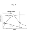
- Fig. 2 is an explanatory diagram for explaining operations of this electronic appliance equipped with the charging function.
- the input terminal 2 of the external power supply is connected via the reverse current blocking diode 3, the switch means 4, and the current detecting means 5 to the rechargeable battery 1.
- the regulator 6 is connected to a circuit point of the switch means 4 on the side of the external power supply, namely, a junction point between the diode 3 and the switch means 4.
- a voltage which is regulated by this regulator 6 is applied to the load 7 and the control means 8, which constitute the electronic appliance, as a power supply.
- an output of the current detecting means 5 is supplied to the control means 8, and an output of the control means 8 is supplied to one input terminal of the NOR circuit 12.
- An external power supply current-carrying detection means 11 is connected via the diode 9 to the input terminal 2 of the external power supply. An output of this external power supply current-carrying detection means 11 is supplied via the inverter 11 to another input terminal of the NOR circuit 12.
- the switch means 4 is constituted by an MOS-FET, a diode, and the like.
- the switch means 4 is arranged in such a manner that this switch means 4 is changed by receiving an output signal of the control means 8 supplied via the above-described NOR circuit 12 into an ON state, a half ON state, and an OFF state, respectively.
- the current detecting means 5 is constructed of a resistor and a means for monitoring a voltage across both ends of this resistor.
- This resistor owns a relatively small resistance value, and is connected between the switch means 4 and the rechargeable battery 1.
- the control means 8 is arranged in such a manner that this control means 8 directly detects a voltage of the rechargeable battery 1, and outputs such a signal which causes the switch means 4 to be brought into three states, namely the ON state, the half ON state, and the OFF state in accordance with this voltage detection result and the current detection result of the current detecting means 5 (will be explained later).
- the voltage of the external power supply applied to the input terminal 2 is normally higher than, or equal to 5.8 V.
- the battery voltage must be set that this battery voltage does not become higher than, or equal to 4.2 V.
- a charge current must be set that this charge current does not become larger than, or equal to 700 mA.
- the switch means 4 is controlled to be brought into the half ON state so as to satisfy such a condition.
- Fig. 2 indicates this state.
- the control means 8 When the voltage of the rechargeable battery 1 is brought into a very low state, this state is sensed by the control means 8, and then, such a signal having a sufficiently large value by which the switch means 4 may be turned ON is outputted from the control means 8. As a result, the switch means 4 is brought into the completely ON state, and a relatively large charge current may flow into the rechargeable battery 1.
- the charge operation is advanced and thus the voltage of the rechargeable battery 1 is gradually increased, the value of the signal outputted from the control means 8 is gradually lowered in response to this voltage increase, and the switch means 4 is brought into the half ON state under which the charge operation is carried out.
- the charge operation is advanced, the voltage of the rechargeable battery 1 is increased and also the charge current flowing into the rechargeable battery 1 is gradually decreased in response to this voltage increase.
- the charge current flowing through the rechargeable battery 1 is detected by the charge current detecting means 5, and the detected current value is applied to the control means 8.
- a resistor having 0.15 ohms is used as the resistor for constituting the charge current detecting means 5
- the charge current flowing through the rechargeable battery 1 can be correctly grasped by detecting the voltage appeared across both ends of this resistor.
- control means 8 also monitors the charge current flowing through the rechargeable battery 1, and when the charge current is lowered to a certain constant value, for example, 50 mA, the control means 8 senses this charge current and controls the switch means 4 to be brought into the OFF state.
- the switch means 4 is constituted by the MOS-FET, the diode, andthe like, the complete OFF state of this switch means 4 cannot be obtained.
- the external power supply is connected to the input terminal 2 since the potential at the input side of the regulator 6 never becomes lower than the potential at the rechargeable battery 1, the electron charges which are charged into the rechargeable battery 1 are not consumed via the switch means 4 and the regulator 6 by the load 7 and the control means 8 even under this condition, but the necessary power supply voltage may be applied only from the external power supply input terminal 2.
- the rechargeable battery 1 can be set to the full charge state even in any timing until the electronic appliance is removed from the charging unit and the like and is electrically cut out from the external power supply.
- the lithium ion battery is employed as the rechargeable battery.
- a nickel hydrogen battery, and other rechargeable batteries may be similarly employed.
- the current detecting means 5 is provided at the circuit point on the side of the rechargeable battery 1 of the switch means 4.
- this current detecting means 5 may be provided at the circuit point on the side of the external power supply of the switch means 4.
- the current detecting means 5 may be provided at a position where the charge current flows into the rechargeable battery 1.
- the external current-carrying detection circuit 10 is separately provided in order to detect this fact.
- a means for detecting an application condition of an external power supply voltage is provided in the control means 8.
- Fig. 3 is a functional block diagram of an electronic appliance equipped with a charging function according to a second embodiment mode of the present invention. It should be understood that the same reference numerals shown in Fig. 1 will be employed as those for indicating the same circuit elements shown in Fig. 3. A different point of this electronic appliance is such that a diode 13 is connected to the external power supply 2, an output side of this diode 13 is connected to the control means 8, and then, connection/disconnection of the external power supply 2 is directly detected by the control means 8. Even in such a case that the electronic appliance is arranged in this manner, it is easily possible to arrange that when the external power supply 2 is not connected, the switch means 4 can be forcibly turned ON under control of the above-described control means 8.
- the control means 8 since the power supply voltage applied to the control means 8 is applied from the input terminal 2 via the diode 3 and the regulator 6, the sufficiently high power supply voltage is applied.
- the control means 8 receives only the power supply voltage from the rechargeable battery 1, this power supply voltage is slightly lower than the power supply voltage obtained when the external power supply is connected. As a result, if a difference between these power supply voltage is detected by the control means 8, then the control means 8 can readily detect as to whether or not the external power supply is connected to the electronic appliance.
- the control means 8 controls the switch means 4 to be turned from the ON state into the half ON state and the OFF state based upon the output signal from the current detecting means 5. In the case that it is so detected that the external power supply is not connected, the control means 8 automatically controls the switch means 4 to be brought into the ON state.
- the voltage of the rechargeable battery 1 is not dropped by the above-described resistor which constitutes the current detecting means, but may be effectively applied via the switch 4 and the regulator 6 to the load 7 and the control means 8.
- Fig. 4 is an electronic connection diagram for schematically showing a third embodiment mode of an electronic appliance equipped with a charging unit according to the present invention.
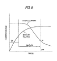
- Fig. 5 is an explanatory diagram for explaining operations of the respective units of the electronic appliance according to the third embodiment mode.
- an input terminal 2 of an external power supply is connected via a reverse current blocking diode 3, a switch means 4, and a current detecting means 5 to a rechargeable battery 1.
- a regulator 6 is connected to a circuit point of the switch means 4 on the external power supply side, namely a connection point between the diode 3 and the switch means 4.
- a voltage which is regulated by this regulator 6 is applied as a power supply to a first load 7 and a control means 8, which constitute the electronic appliance.
- a second load 13 is directly connected to the rechargeable battery 1, and is arranged to directly receive a supply of electric power from the rechargeable battery 1.
- a supply of electric power from the rechargeable battery 1 becomes insufficient. In this case, it is apparent that a lack of this electric power may be supplied from the external power supply 2.
- the second load 13 such a power amplifier is selected. That is, when this power amplifier is brought into operation condition, this power amplifier consumes relatively high power.
- power consumption of an entire load is approximately 900 mA under operating condition of this portable telephone, whereas since approximately 600 mA is consumed only by the power amplifier, such a circuit containing at least the power amplifier maybe desirably employed as the second load in this case.
- an output of the current detectingmeans 5 is supplied to the control means 8, and an output of the control means 8 is supplied to one input terminal of the NOR circuit 12.
- An external power supply current-currying detection circuit 10 is connected via a diode 9 to the input terminal 2 of the external power supply. An output of this external power supply current-carrying detection circuit 10 is supplied via an inverter 11 to another input terminal of the NOR circuit 12.
- the switch means 4 is constituted by an MOS-FET, a diode, and the like.
- the switch means 4 is arranged in such a manner that this switch means 4 is switched by receiving an output signal of the above-described NOR circuit 12 into an ON state, a half ON state, and an OFF state, respectively.
- the current detecting means 5 is constructed of a resistor and a means for monitoring a voltage across both ends of this resistor. This resistor owns a relatively small resistance value, and is connected between the switch means 4 and the rechargeable battery 1.
- the voltage of the external power supply applied to the input terminal 2 is normally higher than, or equal to 5.8 V.
- the battery voltage must be set that this battery voltage does not become higher than, or equal to 4.2 V.
- a charge current must be set that this charge current does not become larger than, or equal to 700 mA.
- the switch means 4 is controlled to be brought into the half ON state so as to satisfy such a condition.
- Fig. 5 indicates this condition.
- the switch means 4 is set under ON state, and thus, a large charge current may flow into the rechargeable battery 1.
- the switch means 4 is brought into the half ON state under which the charge operation is further carried out. While the charge operation is advanced, a voltage appeared across both ends of the rechargeable battery 1 is gradually increased, and the charge current flowing through the rechargeable battery 1 is gradually decreased.
- the charge current flowing through the rechargeable battery 1 is detected by the charge current detecting means 5, and the detected current value is applied to the control means 8.
- a resistor having 0.15 ohms is used as the resistor for constituting the charge current detecting means 5, when a voltage across both of this resistor is 150 mV, this implies that such a charge current having 1 A flows through this resistor.
- the control means 8 also monitors the charge current flowing through the rechargeable battery 1, and when the charge current is lowered to a certain constant value I 0 , for example, 50 mA, the control means 8 senses this charge current and controls the switch means 4 to be brought into the OFF state.
- a discharge current caused by the second load 13 under non-operation condition can be essentially neglected. Even in such a case that the discharge current cannot be neglected, the discharge current from the rechargeable battery 1 is very small, as compared with the prior art. Even when the electronic appliance is connected to the external power supply under such a condition that the charge operation is completed, the rechargeable battery 1 may be kept under substantially full-charge state any time.
- the switch means 4 is constituted by the MOS-FET, the diode, and the like, the complete OFF state of this switch means 4 may not be obtained.
- the external power supply is connected to the input terminal 2 since the potential at the input side of the regulator 6 never becomes lower than the potential at the rechargeable battery 1, the electron charges which are charged into the rechargeable battery 1 are not consumed via the switch means 4 and the regulator 6 by the first load 7 and the control means 8 even under this condition, but the necessary power supply voltage may be applied only from the external power supply input terminal 2.
- the rechargeable battery 1 can be set to the full charge state even in any timing until the electronic appliance is removed from the charging unit and the like and is electrically cut out from the external power supply.
- the lithium ion battery is employed as the rechargeable battery.
- a nickel hydrogen battery, and other rechargeable batteries may be similarly employed.
- the current detecting means 5 is provided on the side of the rechargeable battery 1 of the switch means 4.
- this current detecting means 5 may be provided on the side of the external power supply.
- the current detecting means 5 may be provided at a position where the charge current flows into the rechargeable battery 1.
- the circuit containing the power amplifier is selected as the second load.
- a transmission circuit, a reception circuit, and other circuits may be independently selected in addition to the power amplifier, as the second load. Further, these circuits may be selectively combined with each other as the second load.
- the external current-carrying detection circuit 10 when the external power supply voltage is not applied, the external current-carrying detection circuit 10 is separately provided in order to detect this fact.
- a means for detecting an application condition of an external power supply voltage may be provided in the control means 8.
- a diode 14 is connected to the external power supply 2, an output side of this diode 14 is connected to the control means 8, and then, connection/disconnection of the external power supply 2 is detected by the control means 8.
- the switch means 4 may be turned ON under control of the control means 8 in response to this detection result.
- the electronic appliance may be operated in a similar manner to that of the above-described electronic appliance.
- the power supply voltage applied to the control means 8 is applied from the input terminal 2 via the diode 3 and the regulator 6, and the sufficiently high power supply voltage is applied.
- the control means 8 receives only the power supply voltage from the rechargeable battery 1, this power supply voltage is slightly lower than the power supply voltage obtained when the external power supply is connected. As a result, if a difference between these power supply voltages is detected by the control means 8, then the control means 8 can readily detect as to whether or not the external power supply is connected to the electronic appliance.
- control means 8 controls the switch means 4 to be turned from the ON state into the half ON state and the OFF state based upon the output signal from the current detecting means 5. In the case that the external power supply is not connected, the control means 8 automatically controls the switch means 4 to be brought into the ON state.
- the voltage of the rechargeable battery 1 is not dropped by the above-described resistor which constitutes the current detecting means, but may be effectively applied via the switch 4 and the regulator 6 to the load 7 and the control means 8.
- the electronic appliance is arranged in such a manner that when the charge operation is carried out, the external power supply is connected via the charging switch means to the rechargeable battery, the load which constitutes the electronic appliance is connected to the circuit point of the charging switch means on the side of the external power supply.
- the switch means is turned OFF, then the rechargeable battery is not essentially and unnecessarily discharged via the load, the control means, and the like.
- the rechargeable battery can be used under sufficiently full charge condition.
- both the detecting means and the control means are provided, while the detecting means detects the current flowing through the rechargeable battery during the charge operation, and the control means controls the charging switch means in such a manner that the charging switch means is turned OFF when the completion of the charge operation of the rechargeable battery is detected based upon the output of this detecting means.
- the control means can correctly sense the completion of the charge operation based upon the output of the detecting means for detecting the current flowing through the rechargeable battery, and can interrupt the charge operation.
- both the external current-carrying detection means and the means for forcibly turning ON the switch means are provided, while the external current-carrying detection means detects the current-carrying operation of the external power supply, and when this external current-carrying detection means detects that no current-carrying operation is performed by the external power supply, this means forcibly turns ON the switch means.
- the switch means is forcibly turned ON.
- the switch means when the electronic appliance is cut out from the external power supply, the switch means is necessarily turned ON, and while the rechargeable battery is used as the power supply, the current-carrying operation to the'load and the control means, which constitute the electronic appliance, can be continuously and correctly carried out.
- the rechargeable battery is connected via the charging switch means to the external power supply
- the first load which constitutes the electronic appliance is connected to the circuit point of the charging switch means on the side of the external power supply
- the second load is connected to the circuit point of the switch means on the side of the rechargeable battery.
- both the detecting means and the control means are provided, while the detecting means detects the current flowing through the rechargeable battery during the charge operation, and the control means controls the charging switch means in such a manner that the charging switch means is turned OFF when the completion of the charge operation of the rechargeable battery is detected based upon the output of this detecting means.
- the control means can correctly sense the completion of the charge operation based upon the output of the detecting means for detecting the current flowing through the rechargeable battery, and can interrupt the charge operation.
- both the external current-carrying detection means and the means for forcibly turning ON the switch means are provided, while the external current-carrying detection means detects the current-carrying operation of the external power supply, and when thisexternalcurrent-carrying detection means detects that no current-carrying operation is performed by the external power supply, this means forcibly turns ON the switch means.
- the switch means is forcibly turned ON.
Landscapes
- Engineering & Computer Science (AREA)
- Power Engineering (AREA)
- Charge And Discharge Circuits For Batteries Or The Like (AREA)
Abstract
Description
Claims (7)
- An electronic appliance equipped with a charging function wherein:when a charge operation is carried out, an external power supply is connected via a charging switch means to a rechargeable battery; and a load which constitutes an electronic appliance is connected to a circuit point of said charging switch means on the side ot said external power supply.
- An electronic appliance equipped with a charging function as claimed in claim 1, comprising:detection means for detecting a current flowing through the rechargeable battery when the charge operation is carried out; andmeans for turning OFF said charging switch means when a completion of the charge operation of the rechargeable battery is detected based upon an output of said detection means.
- An electronic appliance equipped with a charging function as claimed in claim 2, comprising:external current-carrying detection means for detecting a current-carrying operation of the external power supply; andmeans for forcibly turning ON said switch means when said external current-carrying detection means detects that the current-carrying operation by said external power supply is not performed.
- An electronic appliance equipped with a charge function wherein:a rechargeable battery is arranged so as to be connected via a charging switch means to an external power supply;a first load which constitutes the electronic appliance is connected to a circuit point of said switch means on the side of said external power supply; anda second load which consumes high electric power when said second load such as a power amplifier is operated is connected to a circuit point of said charging switch means on the side of the rechargeable battery.
- An electronic appliance equipped with a charging function as claimed in claim 4, comprising:detection means for detecting a current flowing through the rechargeable battery when the charge operation is carried out; andcontrol means for controlling said charging switch means to be turned OFF when a completion of the charge operation of the rechargeable battery is detected based upon an output of said detection means.
- An electronic appliance equipped with a charging function as claimed in claim 5, comprising:external current-carrying detection means for detecting a current-carrying operation of the external power supply; andmeans for forcibly turning ON said switch means when said external current-carrying detection means detects that the current-carrying operation by said external power supply is not performed.
- An electronic appliance equipped with a charging function as claimed in claim 6 wherein:means for forcibly turning ON said switch means is provided with said control means.
Applications Claiming Priority (5)
| Application Number | Priority Date | Filing Date | Title |
|---|---|---|---|
| JP2001121661A JP2002320333A (en) | 2001-04-19 | 2001-04-19 | Electronic equipment with charging function |
| JP2001121661 | 2001-04-19 | ||
| JP2001160906A JP2002354694A (en) | 2001-05-29 | 2001-05-29 | Electronic equipment with charging function |
| JP2001160906 | 2001-05-29 | ||
| PCT/JP2002/003777 WO2002087055A1 (en) | 2001-04-19 | 2002-04-16 | Electronic apparatus having charging function |
Publications (2)
| Publication Number | Publication Date |
|---|---|
| EP1381138A1 true EP1381138A1 (en) | 2004-01-14 |
| EP1381138A4 EP1381138A4 (en) | 2004-05-12 |
Family
ID=26613874
Family Applications (1)
| Application Number | Title | Priority Date | Filing Date |
|---|---|---|---|
| EP02717178A Withdrawn EP1381138A4 (en) | 2001-04-19 | 2002-04-16 | ELECTRONIC DEVICE HAVING A CHARGING FUNCTION |
Country Status (4)
| Country | Link |
|---|---|
| US (1) | US20030137283A1 (en) |
| EP (1) | EP1381138A4 (en) |
| CN (1) | CN1461514A (en) |
| WO (1) | WO2002087055A1 (en) |
Families Citing this family (8)
| Publication number | Priority date | Publication date | Assignee | Title |
|---|---|---|---|---|
| US7876068B2 (en) * | 2003-10-24 | 2011-01-25 | International Components Corporation | Battery charge indicator |
| US7629709B2 (en) * | 2004-12-29 | 2009-12-08 | Freescale Semiconductor, Inc. | Regulation of a DC to DC converter |
| US20070080665A1 (en) * | 2005-07-29 | 2007-04-12 | Paul Christopher R | System and method for monitoring power supplied to a battery |
| TWI346438B (en) * | 2006-05-02 | 2011-08-01 | Mediatek Inc | Power supply |
| JP5066909B2 (en) * | 2006-12-08 | 2012-11-07 | 日本電気株式会社 | Electronic device, charger, charging system, and charging method |
| US7825615B2 (en) * | 2007-10-16 | 2010-11-02 | Glj, Llc | Intelligent motorized appliances with multiple power sources |
| EP2571150A3 (en) * | 2011-09-16 | 2018-02-28 | Braun GmbH | Power-supply circuit for an electrical appliance having a battery and a dc-to-dc converter |
| CN103715726B (en) * | 2012-09-29 | 2016-12-21 | 联芯科技有限公司 | Charging device and method for AC charger |
Family Cites Families (19)
| Publication number | Priority date | Publication date | Assignee | Title |
|---|---|---|---|---|
| JPH0642768B2 (en) * | 1984-02-01 | 1994-06-01 | 松下電工株式会社 | Electrical equipment |
| JP2789778B2 (en) * | 1990-04-12 | 1998-08-20 | 三菱電機株式会社 | Power supply |
| JP2754963B2 (en) * | 1991-08-08 | 1998-05-20 | 松下電器産業株式会社 | Power switching circuit |
| JP2776675B2 (en) * | 1992-01-29 | 1998-07-16 | 日本電気株式会社 | In-vehicle adapter device for mobile phones |
| JP2812066B2 (en) * | 1992-06-04 | 1998-10-15 | 三菱電機株式会社 | Power supply voltage switching device for vehicles |
| JP3291530B2 (en) * | 1992-09-17 | 2002-06-10 | ソニー株式会社 | Battery protection circuit |
| US5557188A (en) * | 1994-02-01 | 1996-09-17 | Sun Microsystems, Inc. | Smart battery system and interface |
| JP2776493B2 (en) * | 1994-08-12 | 1998-07-16 | インターナショナル・ビジネス・マシーンズ・コーポレイション | Power supply device for electronic equipment and control method thereof |
| JP2716374B2 (en) * | 1994-09-28 | 1998-02-18 | インターナショナル・ビジネス・マシーンズ・コーポレイション | Information processing equipment, power supply device and power supply method for information processing equipment |
| JP2762950B2 (en) * | 1995-03-29 | 1998-06-11 | 日本電気株式会社 | Power switching circuit |
| JP3324930B2 (en) * | 1996-05-31 | 2002-09-17 | 富士通株式会社 | Power supply |
| US6043626A (en) * | 1996-10-29 | 2000-03-28 | Ericsson Inc. | Auxiliary battery holder with multicharger functionality |
| US5925942A (en) * | 1997-07-16 | 1999-07-20 | Motorola, Inc. | Power supply control apparatus and method suitable for use in an electronic device |
| JPH11234915A (en) * | 1998-02-20 | 1999-08-27 | Fujitsu Ltd | Power supply device having rechargeable battery and method of charging / discharging a plurality of batteries |
| JP2000014043A (en) * | 1998-06-05 | 2000-01-14 | Internatl Business Mach Corp <Ibm> | Uninterruptive power supply |
| SE514786C2 (en) * | 1998-09-02 | 2001-04-23 | Scania Cv Ab | Electrical system for motor vehicles with dual batteries |
| JP3220100B2 (en) * | 1999-01-26 | 2001-10-22 | 埼玉日本電気株式会社 | Power supply circuit and power supply method |
| DE29913613U1 (en) * | 1999-08-04 | 2000-09-28 | Siemens AG, 80333 München | Arrangement for monitoring a battery consisting of several battery sub-units connected in series |
| JP2002300728A (en) * | 2001-03-30 | 2002-10-11 | Matsushita Electric Ind Co Ltd | Mobile phone with charging function |
-
2002
- 2002-04-16 CN CN02801270A patent/CN1461514A/en not_active Withdrawn
- 2002-04-16 US US10/297,072 patent/US20030137283A1/en not_active Abandoned
- 2002-04-16 EP EP02717178A patent/EP1381138A4/en not_active Withdrawn
- 2002-04-16 WO PCT/JP2002/003777 patent/WO2002087055A1/en not_active Ceased
Also Published As
| Publication number | Publication date |
|---|---|
| EP1381138A4 (en) | 2004-05-12 |
| WO2002087055A1 (en) | 2002-10-31 |
| CN1461514A (en) | 2003-12-10 |
| US20030137283A1 (en) | 2003-07-24 |
Similar Documents
| Publication | Publication Date | Title |
|---|---|---|
| US5777399A (en) | Portable electronic apparatus and charge controlling method for portable electronic apparatus | |
| US6191498B1 (en) | Power-supplying device for generating different voltage outputs | |
| US5963015A (en) | External battery charger for use with a battery powered electronic device and an extra battery | |
| EP0657982B1 (en) | Battery system for portable electric equipment | |
| US6118250A (en) | Power supply assembly for hand-held communications device | |
| US5859481A (en) | Auxiliary battery sensor switch | |
| US7183748B1 (en) | Electric charger and power supply device for portable terminal | |
| EP0948822B1 (en) | Belt clip holder with auxiliary battery | |
| US6051956A (en) | Rechargeable battery pack with pre-end signal output terminal and electronic device containing rechargeable battery pack | |
| US20040004458A1 (en) | Charging control circuit, charger, power supply circuit, information processing device, and battery pack | |
| EP1096638A1 (en) | Electronic device and method of controlling electronic devices | |
| JP2001283934A (en) | Battery pack identification device and battery pack | |
| EP1381138A1 (en) | Electronic apparatus having charging function | |
| JP2914425B2 (en) | Mobile phone with automatic power control function | |
| JP3581428B2 (en) | Rechargeable power supply | |
| JP2007110820A (en) | Battery pack | |
| EP1086521B1 (en) | Two-wire multi-rate battery charger | |
| US6472849B1 (en) | Reverse blocking function integrated into charging circuit | |
| JPH0759266A (en) | Secondary battery charging circuit | |
| JPH0759265A (en) | Battery circuit | |
| JPH1012283A (en) | Battery pack and method for controlling battery pack | |
| JP2002320333A (en) | Electronic equipment with charging function | |
| EP1253696A1 (en) | A method of charging a battery | |
| JP2002354694A (en) | Electronic equipment with charging function | |
| US20040207363A1 (en) | Method of charging a battery |
Legal Events
| Date | Code | Title | Description |
|---|---|---|---|
| PUAI | Public reference made under article 153(3) epc to a published international application that has entered the european phase |
Free format text: ORIGINAL CODE: 0009012 |
|
| 17P | Request for examination filed |
Effective date: 20021204 |
|
| AK | Designated contracting states |
Kind code of ref document: A1 Designated state(s): AT BE CH CY DE DK ES FI FR GB GR IE IT LI LU MC NL PT SE TR |
|
| AX | Request for extension of the european patent |
Extension state: AL LT LV MK RO SI |
|
| A4 | Supplementary search report drawn up and despatched |
Effective date: 20040331 |
|
| RIC1 | Information provided on ipc code assigned before grant |
Ipc: 7H 02J 7/00 B Ipc: 7G 05F 1/565 A |
|
| 17Q | First examination report despatched |
Effective date: 20070329 |
|
| STAA | Information on the status of an ep patent application or granted ep patent |
Free format text: STATUS: THE APPLICATION IS DEEMED TO BE WITHDRAWN |
|
| 18D | Application deemed to be withdrawn |
Effective date: 20070809 |