EP1381040A2 - Optical pickup having optical base made of different kinds of materials - Google Patents
Optical pickup having optical base made of different kinds of materials Download PDFInfo
- Publication number
- EP1381040A2 EP1381040A2 EP03254144A EP03254144A EP1381040A2 EP 1381040 A2 EP1381040 A2 EP 1381040A2 EP 03254144 A EP03254144 A EP 03254144A EP 03254144 A EP03254144 A EP 03254144A EP 1381040 A2 EP1381040 A2 EP 1381040A2
- Authority
- EP
- European Patent Office
- Prior art keywords
- optical
- lens
- laser diode
- optical pickup
- photodiode
- Prior art date
- Legal status (The legal status is an assumption and is not a legal conclusion. Google has not performed a legal analysis and makes no representation as to the accuracy of the status listed.)
- Granted
Links
Images



Classifications
-
- G—PHYSICS
- G11—INFORMATION STORAGE
- G11B—INFORMATION STORAGE BASED ON RELATIVE MOVEMENT BETWEEN RECORD CARRIER AND TRANSDUCER
- G11B7/00—Recording or reproducing by optical means, e.g. recording using a thermal beam of optical radiation by modifying optical properties or the physical structure, reproducing using an optical beam at lower power by sensing optical properties; Record carriers therefor
- G11B7/12—Heads, e.g. forming of the optical beam spot or modulation of the optical beam
- G11B7/22—Apparatus or processes for the manufacture of optical heads, e.g. assembly
-
- G—PHYSICS
- G11—INFORMATION STORAGE
- G11B—INFORMATION STORAGE BASED ON RELATIVE MOVEMENT BETWEEN RECORD CARRIER AND TRANSDUCER
- G11B7/00—Recording or reproducing by optical means, e.g. recording using a thermal beam of optical radiation by modifying optical properties or the physical structure, reproducing using an optical beam at lower power by sensing optical properties; Record carriers therefor
- G11B7/12—Heads, e.g. forming of the optical beam spot or modulation of the optical beam
Definitions
- the present invention relates to an optical pickup that is movably mounted on a mounting object in an optical disk drive or the like.
- CD-Rs Compact Discs Recordable
- CD-RWs Compact Discs Rewritable
- the CD-R is a recording medium that is writable, but not deletable.
- the CD-RW is a recording medium that is writable and deletable.
- CD-DAs CD-DAs
- a dedicated device and writing application are necessary for writing to the CD-R or CD-RW, while reading from the CD-R or CD-RW can be performed using a normal CD-ROM drive.
- the CD-R, CD-RW, CD-ROM and audio CD, and a DVD-ROM, a DVD-R, a DVD-RAM and so on will be collectively referred to as "optical disks".
- an optical pickup movably mounted in an optical disk drive is used.
- the optical pickup includes an optical base having a sliding portion that slidably engages with a guide rod provided in the optical disk drive.
- Various optical components and a laser diode are mounted on the optical base.
- the characteristic first required is being excellent in radiation property.
- the reason for this is that inasmuch as heat generation of a laser diode upon writing is much greater than that upon reading, unless a sufficient measure for radiation is taken, the life duration or characteristic of the laser diode may be deteriorated.
- a material of the optical base should be excellent in radiation property so that metal such as zinc or magnesium is more suitable than resin.
- the characteristic next required is being as light as possible.
- the reason for this is that inasmuch as quick movement is required for the high-speed optical pickup, the optical base should be lightweight. If resin, zinc and magnesium are compared in density, zinc is the largest, then resin and magnesium follow in the order named.
- Table 1 is obtained.
- o ⁇ represents “excellent”, ⁇ represents “normal”, ⁇ represents “bad”, and X represents “extremely bad”.
- Material comparison item radiation weight price Resin X ⁇ o ⁇ Zinc ⁇ ⁇ ⁇ Magnesium ⁇ ⁇ ⁇
- a n optical pickup mounted movably relative to a mounting object.
- the optical pickup comprises an optical base, optical components; and, and a laser diode optically connected to said optical components.
- the optical base comprises a sliding portion slidable relative to said mounting object, a component mounting portion mounted with said optical components, and a laser diode fixing portion fixed with said laser diode.
- the sliding portion and said component mounting portion are formed by molding resin, and said laser diode fixing portion is formed by an iron plate.
- the shown optical pickup is usable in an optical disk drive that is installed in an electronic device such as a personal computer.
- the optical pickup uses as a light-emitting element a laser diode 1 being a semiconductor laser that generates a laser beam.
- the laser beam emitted from the laser diode 1 enters a beam splitter 3 via a diffraction grating 2 and is split by the beam splitter 3, so that a portion of the laser beam enters a monitor 4 having a photodiode.
- the remaining portion of the laser beam is applied to an optical disk 8 via a collimator lens 5, a raising mirror 6 and an objective lens 7.
- the monitor 4 detects the intensity of the laser beam.
- the detected intensity is used for controlling an operation of the laser diode 1. In this manner, data can be recorded on the optical disk 8 using the laser beam emitted from the laser diode 1.
- optical components The beam splitter 3, the monitor 4, the collimator lens 5, the raising mirror 6, the objective lens 7 and the sensor lens 9 arranged on the path of the laser beam will be collectively referred to as "optical components". These optical components along with the laser diode 1 and the photodiode 11 are retained on an optical base serving as a housing of the optical pickup.
- the raising mirror 6 and the objective lens 7 will be combinedly referred to as a "lens actuator".
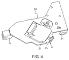
- the optical base is represented by reference numeral 20 in the figures.
- the optical base 20 has a sliding portion 21.
- the sliding portion 21 is slidably mounted on a guide rod (not shown), i.e. a mounting object, of the optical disk drive so that the optical base 20 is movably mounted in the optical disk drive.
- the optical base 20 comprises a laser diode fixing portion 22 of an arch shape, a diffraction grating mounting portion 23 composed of a pair of pillar-like portions, a collimator lens mounting portion 24 composed of a pair of pillar-like portions, a plate-like photodiode fixing portion 25, and an actuator mounting portion 26 composed of a pair of plate-like portions, all of which are projectingly provided on an upper surface 20a of the optical base 20.
- One of the pillar-like portions of the diffraction grating mounting portion 23 and one of the pillar-like portions of the collimator lens mounting portion 24 are unified together. Specifically, one pillar-like portion is used for both the diffraction grating mounting portion 23 and the collimator lens mounting portion 24.
- the laser diode 1 is brought into contact with the laser diode fixing portion 22 and fixed thereto.
- the diffraction grating 2 is fixedly retained to the diffraction grating mounting portion 23.
- the collimator lens 5 is fixedly retained to the collimator lens mounting portion 24.
- the photodiode 11 is attached to the photodiode fixing portion 25.
- the foregoing lens actuator is mounted in the actuator mounting portion 26.
- On a top surface of each plate-like portion of the actuator mounting portion 26 is formed a V-shaped recess 26a for adjusting the tangential skew of the lens actuator.
- the actuator mounting portion 26 also serves as a portion to fix the beam splitter 3.
- the optical base 20 is formed by outsert-molding resin to an iron plate.
- the sliding portion 21 that requires excellent slidability is formed by resin molding of at least one of polypropylene sulfide, polyoxymethyene (polyacetal), and liquid crystal polymer
- the laser diode fixing portion 22 and the photodiode fixing portion 25 that require an excellent radiation property are formed by pressing to bend the iron plate, and a component mounting portion 27 that requires a complicated shape is formed by resin molding.
- the component mounting portion 27 comprises the foregoing diffraction grating mounting portion 23, collimator lens mounting portion 24 and actuator mounting portion 26 that are formed integral with each other.
- the sensor lens 9 is fixedly retained to the component mounting portion 27.
- the laser diode 1 is separated from the laser diode fixing portion 22 with a clearance therebetween before mounting as shown in Fig. 5, but is finally brought into contact with the laser diode fixing portion 22 so as to be fixed thereto as shown in Fig. 6.
- the laser diode 1 is in direct contact with the laser diode fixing portion 22 made of part of the iron plate of the optical base 20, and thus heat generated by the laser diode 1 is conducted from a portion of the direct contact over the iron plate, so that the whole of the iron plate serves as a radiation plate. Therefore, the required characteristic can be fully achieved with respect to the heat radiation.
- the optical base 20 is formed from the heavy iron plate and the lightweight resin, it is easy to make the optical base 20 lighter than an optical base having the same shape and size and formed only from zinc. Therefore, the required characteristic can also be easily achieved with respect to the weight.
- the manufacturing cost can be reduced as compared with a case wherein an optical base is formed by die casting of zinc or magnesium.
- the sliding portion 21 from the resin, a sliding member that is required in case of the die-cast metal is not required. Therefore, the total cost can be largely reduced, thereby realizing the optical pickup having the low-priced optical base.
Landscapes
- Physics & Mathematics (AREA)
- Optics & Photonics (AREA)
- Optical Head (AREA)
Abstract
Description
| Material | comparison item | ||
| radiation | weight | price | |
| Resin | X | ○ | o ○ |
| Zinc | ○ | Δ | ○ |
| Magnesium | ○ | ○ | Δ |
Claims (9)
- An optical pickup mounted movably relative to a mounting object, said optical pickup comprising:wherein said optical base comprises a sliding portion slidable relative to said mounting object, a component mounting portion mounted with said optical components, and a laser diode fixing portion fixed with said laser diode, andan optical base;optical components; anda laser diode optically connected to said optical components,
wherein said sliding portion and said component mounting portion are formed by molding resin, and said laser diode fixing portion is formed by an iron plate. - The optical pickup according to claim 1, wherein said resin is outsert-molded to said iron plate.
- The optical pickup according to claim 1, wherein said laser diode is in direct contact with said laser diode fixing portion.
- The optical pickup according to claim 1, wherein said optical components include a diffraction grating, a collimator lens, and a lens actuator,
said component mounting portion comprising:a diffraction grating mounting portion retaining said diffraction grating;a collimator lens mounting portion retaining said collimator lens; andan actuator mounting portion mounting said lens actuator thereon. - The optical pickup according to claim 4, wherein said lens actuator comprises:an objective lens; anda raising mirror interposed optically between said object lens and said collimator lens.
- The optical pickup according to claim 4, wherein said optical components further including:a monitor; anda beam splitter interposed optically between said diffraction grating and each of said monitor and said collimator lens.
- The optical pickup according to claim 1, further comprising a photodiode optically connected to said optical components, said optical base further comprising a photodiode fixing portion fixed with said photodiode, and said photodiode fixing portion being formed by said iron plate.
- The optical pickup according to claim 7, wherein said optical components include:a monitor opposite to said leaser diode;a diffraction grating placed between said monitor and said leaser diode; a collimator lens opposite to said photodiode;a sensor lens placed between said collimator lens and said photodiode; anda beam splitter placed at a position which is between said monitor and said diffraction grating and between said collimator lens and said sensor lens.
- The optical pickup according to claim 8, wherein said optical components further include:an objective lens; anda raising mirror interposed optically between said object lens and said collimator lens.
Applications Claiming Priority (2)
| Application Number | Priority Date | Filing Date | Title |
|---|---|---|---|
| JP2002191958A JP2004039043A (en) | 2002-07-01 | 2002-07-01 | Optical pickup |
| JP2002191958 | 2002-07-01 |
Publications (3)
| Publication Number | Publication Date |
|---|---|
| EP1381040A2 true EP1381040A2 (en) | 2004-01-14 |
| EP1381040A3 EP1381040A3 (en) | 2004-11-24 |
| EP1381040B1 EP1381040B1 (en) | 2006-08-09 |
Family
ID=29728384
Family Applications (1)
| Application Number | Title | Priority Date | Filing Date |
|---|---|---|---|
| EP03254144A Expired - Lifetime EP1381040B1 (en) | 2002-07-01 | 2003-06-30 | Optical pickup having optical base made of different kinds of materials |
Country Status (4)
| Country | Link |
|---|---|
| US (1) | US20040008607A1 (en) |
| EP (1) | EP1381040B1 (en) |
| JP (1) | JP2004039043A (en) |
| DE (1) | DE60307383T2 (en) |
Cited By (3)
| Publication number | Priority date | Publication date | Assignee | Title |
|---|---|---|---|---|
| CN100350477C (en) * | 2004-11-03 | 2007-11-21 | 三星电机株式会社 | Optical pickup apparatus and method of combining submount and optical bench of the same |
| EP1923879A1 (en) | 2006-11-20 | 2008-05-21 | Funai Electric Co., Ltd. | Optical pickup apparatus |
| EP2107563A1 (en) * | 2008-04-03 | 2009-10-07 | Funai Electric Co., Ltd. | Light-source holder and optical pickup having same |
Families Citing this family (1)
| Publication number | Priority date | Publication date | Assignee | Title |
|---|---|---|---|---|
| JP2006216114A (en) * | 2005-02-02 | 2006-08-17 | Funai Electric Co Ltd | Optical pickup and optical disk drive provided therewith |
Family Cites Families (10)
| Publication number | Priority date | Publication date | Assignee | Title |
|---|---|---|---|---|
| DE4236181A1 (en) * | 1992-10-27 | 1994-04-28 | Philips Patentverwaltung | Technical device, in particular electromechanical drive for moving information carriers |
| WO1995009418A1 (en) * | 1993-09-27 | 1995-04-06 | Seiko Epson Corporation | Optical head |
| KR19990036225A (en) * | 1996-06-07 | 1999-05-25 | 이데이 노부유끼 | The optical pickup device |
| US6034938A (en) * | 1996-07-30 | 2000-03-07 | Seagate Technology, Inc. | Data storage system having an optical processing flying head |
| KR100224621B1 (en) * | 1996-09-16 | 1999-10-15 | 윤종용 | OPTICAL PICK UP FOR RECORD PLAYING TO COMkpoIBILITY BETWEEN OTHER DISKS |
| JPH11186682A (en) * | 1997-12-22 | 1999-07-09 | Olympus Optical Co Ltd | Substrate with check land |
| JP2000011417A (en) * | 1998-06-26 | 2000-01-14 | Toshiba Corp | Semiconductor laser array and manufacturing method thereof, optical integrated unit, optical pickup, and optical disk drive |
| JP3445938B2 (en) * | 1998-08-24 | 2003-09-16 | 株式会社三協精機製作所 | Optical pickup device |
| KR100604788B1 (en) * | 1998-10-23 | 2006-07-26 | 삼성전자주식회사 | Compatible Optical Pickup Device |
| CN1199160C (en) * | 1999-10-29 | 2005-04-27 | 松下电器产业株式会社 | Optical head and optical head feeding device |
-
2002
- 2002-07-01 JP JP2002191958A patent/JP2004039043A/en not_active Withdrawn
-
2003
- 2003-06-30 EP EP03254144A patent/EP1381040B1/en not_active Expired - Lifetime
- 2003-06-30 DE DE60307383T patent/DE60307383T2/en not_active Expired - Fee Related
- 2003-06-30 US US10/610,893 patent/US20040008607A1/en not_active Abandoned
Cited By (4)
| Publication number | Priority date | Publication date | Assignee | Title |
|---|---|---|---|---|
| CN100350477C (en) * | 2004-11-03 | 2007-11-21 | 三星电机株式会社 | Optical pickup apparatus and method of combining submount and optical bench of the same |
| EP1923879A1 (en) | 2006-11-20 | 2008-05-21 | Funai Electric Co., Ltd. | Optical pickup apparatus |
| EP2107563A1 (en) * | 2008-04-03 | 2009-10-07 | Funai Electric Co., Ltd. | Light-source holder and optical pickup having same |
| US8141110B2 (en) | 2008-04-03 | 2012-03-20 | Funai Electric Co., Ltd. | Light-source holder and optical pickup having same |
Also Published As
| Publication number | Publication date |
|---|---|
| JP2004039043A (en) | 2004-02-05 |
| EP1381040B1 (en) | 2006-08-09 |
| EP1381040A3 (en) | 2004-11-24 |
| DE60307383T2 (en) | 2006-12-07 |
| DE60307383D1 (en) | 2006-09-21 |
| US20040008607A1 (en) | 2004-01-15 |
Similar Documents
| Publication | Publication Date | Title |
|---|---|---|
| US7180838B2 (en) | Optical pickup apparatus with single light source module | |
| EP1381040B1 (en) | Optical pickup having optical base made of different kinds of materials | |
| US7130259B2 (en) | Optical pick-up apparatus | |
| US8387080B2 (en) | Optical pickup apparatus having a heatsink for dissipating heat generated by a laser diode | |
| JPH10334575A (en) | Optical information recording device | |
| JP2008090922A (en) | Optical pickup | |
| EP1657716B1 (en) | Optical pick-up apparatus | |
| US8493831B2 (en) | Compatible optical pickup and optical recording and/or reproducing apparatus employing the same | |
| JP2003272220A (en) | Optical pickup device | |
| KR20060041856A (en) | Small Form Factor Optical Data Storage | |
| JP3843049B2 (en) | Optical pickup device adjusting disk, adjusting method and manufacturing method, and optical reproducing device manufacturing method using the same | |
| US20060120226A1 (en) | Optical pick-up device and optical disk device | |
| KR100565036B1 (en) | Compatible optical pickup apparatus | |
| US7492695B2 (en) | Optical pick-up capable of increasing the quantity of received laser beam | |
| US7251208B2 (en) | Optical pick-up system for use in an optical disk device including use of improved gratings with more efficient beam diffraction | |
| KR19990031138A (en) | Multi-wavelength optical pickup device | |
| JP2005209840A (en) | Semiconductor laser device and optical pickup device | |
| JP2008084452A (en) | Optical pickup | |
| CN100423101C (en) | Transceiver optical module for optical pickup and optical pickup | |
| JP2008090920A (en) | Optical pickup actuator | |
| JP4804286B2 (en) | Optical pickup device | |
| KR20070028533A (en) | Apparatus and method for generating a scanning beam in an optical pickup head, an optical storage system having a small optical pickup head and a small pickup head | |
| JP4184621B2 (en) | Optical head device | |
| KR100557587B1 (en) | Optical distribution adjusting device, recording method and recording system optical pickup device | |
| JP3986464B2 (en) | Disc recording or playback device with pickup tilt adjustment mechanism |
Legal Events
| Date | Code | Title | Description |
|---|---|---|---|
| PUAI | Public reference made under article 153(3) epc to a published international application that has entered the european phase |
Free format text: ORIGINAL CODE: 0009012 |
|
| AK | Designated contracting states |
Kind code of ref document: A2 Designated state(s): AT BE BG CH CY CZ DE DK EE ES FI FR GB GR HU IE IT LI LU MC NL PT RO SE SI SK TR |
|
| AX | Request for extension of the european patent |
Extension state: AL LT LV MK |
|
| PUAL | Search report despatched |
Free format text: ORIGINAL CODE: 0009013 |
|
| AK | Designated contracting states |
Kind code of ref document: A3 Designated state(s): AT BE BG CH CY CZ DE DK EE ES FI FR GB GR HU IE IT LI LU MC NL PT RO SE SI SK TR |
|
| AX | Request for extension of the european patent |
Extension state: AL LT LV MK |
|
| RIC1 | Information provided on ipc code assigned before grant |
Ipc: 7G 11B 7/22 A Ipc: 7G 11B 7/12 B |
|
| 17P | Request for examination filed |
Effective date: 20050517 |
|
| AKX | Designation fees paid |
Designated state(s): DE FR NL |
|
| GRAP | Despatch of communication of intention to grant a patent |
Free format text: ORIGINAL CODE: EPIDOSNIGR1 |
|
| GRAS | Grant fee paid |
Free format text: ORIGINAL CODE: EPIDOSNIGR3 |
|
| GRAA | (expected) grant |
Free format text: ORIGINAL CODE: 0009210 |
|
| AK | Designated contracting states |
Kind code of ref document: B1 Designated state(s): DE FR NL |
|
| PG25 | Lapsed in a contracting state [announced via postgrant information from national office to epo] |
Ref country code: NL Free format text: LAPSE BECAUSE OF FAILURE TO SUBMIT A TRANSLATION OF THE DESCRIPTION OR TO PAY THE FEE WITHIN THE PRESCRIBED TIME-LIMIT Effective date: 20060809 |
|
| REF | Corresponds to: |
Ref document number: 60307383 Country of ref document: DE Date of ref document: 20060921 Kind code of ref document: P |
|
| NLV1 | Nl: lapsed or annulled due to failure to fulfill the requirements of art. 29p and 29m of the patents act | ||
| EN | Fr: translation not filed | ||
| PLBE | No opposition filed within time limit |
Free format text: ORIGINAL CODE: 0009261 |
|
| STAA | Information on the status of an ep patent application or granted ep patent |
Free format text: STATUS: NO OPPOSITION FILED WITHIN TIME LIMIT |
|
| 26N | No opposition filed |
Effective date: 20070510 |
|
| PG25 | Lapsed in a contracting state [announced via postgrant information from national office to epo] |
Ref country code: DE Free format text: LAPSE BECAUSE OF NON-PAYMENT OF DUE FEES Effective date: 20080101 Ref country code: FR Free format text: LAPSE BECAUSE OF FAILURE TO SUBMIT A TRANSLATION OF THE DESCRIPTION OR TO PAY THE FEE WITHIN THE PRESCRIBED TIME-LIMIT Effective date: 20070511 |
|
| PG25 | Lapsed in a contracting state [announced via postgrant information from national office to epo] |
Ref country code: FR Free format text: LAPSE BECAUSE OF FAILURE TO SUBMIT A TRANSLATION OF THE DESCRIPTION OR TO PAY THE FEE WITHIN THE PRESCRIBED TIME-LIMIT Effective date: 20060809 |