EP1380819A1 - Weight measuring equipment and crew weight measuring equipment comprising it - Google Patents
Weight measuring equipment and crew weight measuring equipment comprising it Download PDFInfo
- Publication number
- EP1380819A1 EP1380819A1 EP02717149A EP02717149A EP1380819A1 EP 1380819 A1 EP1380819 A1 EP 1380819A1 EP 02717149 A EP02717149 A EP 02717149A EP 02717149 A EP02717149 A EP 02717149A EP 1380819 A1 EP1380819 A1 EP 1380819A1
- Authority
- EP
- European Patent Office
- Prior art keywords
- measuring equipment
- weight measuring
- arm
- leaf spring
- load
- Prior art date
- Legal status (The legal status is an assumption and is not a legal conclusion. Google has not performed a legal analysis and makes no representation as to the accuracy of the status listed.)
- Withdrawn
Links
Images








Classifications
-
- G—PHYSICS
- G01—MEASURING; TESTING
- G01G—WEIGHING
- G01G19/00—Weighing apparatus or methods adapted for special purposes not provided for in the preceding groups
- G01G19/40—Weighing apparatus or methods adapted for special purposes not provided for in the preceding groups with provisions for indicating, recording, or computing price or other quantities dependent on the weight
- G01G19/413—Weighing apparatus or methods adapted for special purposes not provided for in the preceding groups with provisions for indicating, recording, or computing price or other quantities dependent on the weight using electromechanical or electronic computing means
- G01G19/414—Weighing apparatus or methods adapted for special purposes not provided for in the preceding groups with provisions for indicating, recording, or computing price or other quantities dependent on the weight using electromechanical or electronic computing means using electronic computing means only
- G01G19/4142—Weighing apparatus or methods adapted for special purposes not provided for in the preceding groups with provisions for indicating, recording, or computing price or other quantities dependent on the weight using electromechanical or electronic computing means using electronic computing means only for controlling activation of safety devices, e.g. airbag systems
-
- B—PERFORMING OPERATIONS; TRANSPORTING
- B60—VEHICLES IN GENERAL
- B60N—SEATS SPECIALLY ADAPTED FOR VEHICLES; VEHICLE PASSENGER ACCOMMODATION NOT OTHERWISE PROVIDED FOR
- B60N2/00—Seats specially adapted for vehicles; Arrangement or mounting of seats in vehicles
- B60N2/002—Seats provided with an occupancy detection means mounted therein or thereon
- B60N2/0021—Seats provided with an occupancy detection means mounted therein or thereon characterised by the type of sensor or measurement
- B60N2/0024—Seats provided with an occupancy detection means mounted therein or thereon characterised by the type of sensor or measurement for identifying, categorising or investigation of the occupant or object on the seat
- B60N2/0025—Seats provided with an occupancy detection means mounted therein or thereon characterised by the type of sensor or measurement for identifying, categorising or investigation of the occupant or object on the seat by using weight measurement
-
- B—PERFORMING OPERATIONS; TRANSPORTING
- B60—VEHICLES IN GENERAL
- B60R—VEHICLES, VEHICLE FITTINGS, OR VEHICLE PARTS, NOT OTHERWISE PROVIDED FOR
- B60R21/00—Arrangements or fittings on vehicles for protecting or preventing injuries to occupants or pedestrians in case of accidents or other traffic risks
- B60R21/01—Electrical circuits for triggering passive safety arrangements, e.g. airbags, safety belt tighteners, in case of vehicle accidents or impending vehicle accidents
- B60R21/015—Electrical circuits for triggering passive safety arrangements, e.g. airbags, safety belt tighteners, in case of vehicle accidents or impending vehicle accidents including means for detecting the presence or position of passengers, passenger seats or child seats, and the related safety parameters therefor, e.g. speed or timing of airbag inflation in relation to occupant position or seat belt use
- B60R21/01512—Passenger detection systems
- B60R21/01516—Passenger detection systems using force or pressure sensing means
-
- B—PERFORMING OPERATIONS; TRANSPORTING
- B60—VEHICLES IN GENERAL
- B60N—SEATS SPECIALLY ADAPTED FOR VEHICLES; VEHICLE PASSENGER ACCOMMODATION NOT OTHERWISE PROVIDED FOR
- B60N2/00—Seats specially adapted for vehicles; Arrangement or mounting of seats in vehicles
- B60N2/002—Seats provided with an occupancy detection means mounted therein or thereon
- B60N2/0021—Seats provided with an occupancy detection means mounted therein or thereon characterised by the type of sensor or measurement
- B60N2/0024—Seats provided with an occupancy detection means mounted therein or thereon characterised by the type of sensor or measurement for identifying, categorising or investigation of the occupant or object on the seat
- B60N2/0027—Seats provided with an occupancy detection means mounted therein or thereon characterised by the type of sensor or measurement for identifying, categorising or investigation of the occupant or object on the seat for detecting the position of the occupant or of occupant's body part
-
- B—PERFORMING OPERATIONS; TRANSPORTING
- B60—VEHICLES IN GENERAL
- B60N—SEATS SPECIALLY ADAPTED FOR VEHICLES; VEHICLE PASSENGER ACCOMMODATION NOT OTHERWISE PROVIDED FOR
- B60N2/00—Seats specially adapted for vehicles; Arrangement or mounting of seats in vehicles
- B60N2/002—Seats provided with an occupancy detection means mounted therein or thereon
- B60N2/0021—Seats provided with an occupancy detection means mounted therein or thereon characterised by the type of sensor or measurement
- B60N2/003—Seats provided with an occupancy detection means mounted therein or thereon characterised by the type of sensor or measurement characterised by the sensor mounting location in or on the seat
- B60N2/0031—Seats provided with an occupancy detection means mounted therein or thereon characterised by the type of sensor or measurement characterised by the sensor mounting location in or on the seat mounted on the frame
-
- B—PERFORMING OPERATIONS; TRANSPORTING
- B60—VEHICLES IN GENERAL
- B60N—SEATS SPECIALLY ADAPTED FOR VEHICLES; VEHICLE PASSENGER ACCOMMODATION NOT OTHERWISE PROVIDED FOR
- B60N2210/00—Sensor types, e.g. for passenger detection systems or for controlling seats
- B60N2210/40—Force or pressure sensors
- B60N2210/42—Strain gauges
Definitions
- the present invention relates to a weight measuring equipment for measuring weights of objects, and a driver and a passenger (hereinafter referred to "a person") weight measuring equipment for vehicles using same.
- a weight measuring equipment for example, a person weight measuring equipment for vehicles in particular
- a trend of controlling an operation of safety equipment according to a weight and constitution of a person's body in order to improve a performance of sheet belts and air bags For example, the vehicle judges whether the person getting therein is a child or an adult, and adjusts an expanding gas quantity and an expanding speed or stops the operation of the air bag. Therefore, it is necessary to know the weight of the person sitting on the seat by using some means.
- a system is proposed in that a strain sensor (load cell) is disposed at four corners of seat rails in order to measure the weight of the person by adding the loads vertically applied to the load cell (Japanese Patent Laid-open Publication H11-1153).
- strain sensors for the person weight measuring equipment, there is a demand for a small-sized sensor whose maximum measuring load is about 50 kg.
- strain sensors there are those having a strain gauge stuck (or formed) on a sensor plate which is deformed by the load, those based on a piezoelectric system, and those using a static capacity sensor for detecting the displacement of an elastic member which is deformed by the load.
- the present invention is intended to address such problem, and the object of the invention is to provide a weight measuring equipment and a person weight measuring equipment using the same.
- the weight measuring equipment can improve the detecting resolution by reducing the load applied to the strain detector as much as possible.
- the weight measuring equipment of the present invention comprises a base fixed to an object, a strain detection substrate attached to the base, a fitting pin attached to the strain detection substrate, an arm rotatably attached to the base by a support pin, and a leaf spring with one end attached to the arm and the other end supported by the fitting pin. Also, the weight measuring equipment of the present invention further comprises a second arm with one end receiving the load of the object to be measured and the other end connected to the arm by a link pin.
- Fig. 1 is an exploded perspective view of the present preferred embodiment.
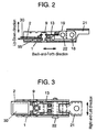
- Fig. 2 is a side sectional view of the present preferred embodiment.
- Fig. 3 is a plan view of the present preferred embodiment.
- strain detection substrate 2 is fixed to base 1, which is to be fixed to an object (not shown), with screws 5a, 5b, 5c, 5d screwed into tapped holes 4a, 4b, 4c, 4d through holes 3a, 3b, 3c, 3d.
- Hole 6 as a point of action at which the load is applied is provided at a point where a straight line connecting the fixing holes 3a and 3d crosses a straight line connecting the holes 3b and 3c.
- Slots 7 for generating a strain of a detectable level, and strain resistor 8 whose resistance varies depending upon the amount of strain are formed around the hole 6.
- Fitting pin 9 is made of a material that withstand more load than the measuring load, and at an end thereof is formed threaded portion 9a, and at a hexagonal head 9c is formed insert portion 9b. Also, the fitting pin 9 is inserted into the hole 6 of the strain detection substrate 2 and fixed by nut 10. And the base 1 is provided with relief hole 1d.
- Arm 19 is provided with hole 16, and is rotatably supported by support pin 22 between rotation support holes 16a and 16b formed in the side wall of the base 1. Also, slide holes 19c, 19d are respectively formed in wing portions 19a and 19b extending from one end of the arm 19.
- Second arm 21 is made from a plate material generally U-shaped, which receives the load of the object to be measured and is vertically movable. Holes 21c, 21d are respectively formed in bent wing portions 21a, 21b so that link pin 18 passes therethrough and the second arm 21 can rotate. With the link pin 18 inserted through the slide holes 19c, 19d and holes 21c, 21d, the second arm 21 is rotatably supported along with the arm 19.
- leaf spring 13 At one end of leaf spring 13 are disposed fixing holes 13a, 13b in positions corresponding to tapped holes 14a, 14b of the arm 19, and at another end thereof is disposed U-shaped notch 13c.
- the notch 13c is inserted to the insert portion 9b of the fitting pin 9.
- the leaf spring 13 is designed so as to be provided with specific spring characteristics according to the measuring load.
- the fitting pin 9 is fixed to the strain detection substrate 2 by using the nut 10.
- the strain detection substrate 2 is fixed to the base 1 by using the screws 5a to 5d.
- the leaf spring 13 is fixed to the arm 19 with screws 23a, 23b.
- the arm 21 is connected to the arm 19 by using the link pin 18.
- the U-shaped notch 13c of the leaf spring 13 is inserted to the insert portion 9b of the fitting pin 9, and the arm 19 is supported by support pin 22 on the base 1.
- the support pin 22 is fixed by nut 23.
- the ratio of the distance between the fitting pin 9 and the support pin 22 and the distance from the support pin 22 to the link pin 18 is freely variable, and therefore, it is possible to greatly reduce the load applied to the strain detection substrate 2 in order to enhance the detecting resolution.
- the equipment of the present preferred embodiment is unitized, it is easy to build the equipment in various types of equipment. Further, the number of assembling steps can be reduced, and it is unnecessary to adjust a sensor characteristics at a time of assembly.
- the above configuration involves no problem in the case of normal weight measurement, but when a load exceeding the maximum measuring load is applied to the equipment via the arm 21, the load is also applied to the leaf spring 13 and strain detection substrate 2. As a result, there is a possibility of permanent deformation or damage of the leaf spring 13, or breakdown of the strain detection substrate 2. As a countermeasure, a possible method is to increase withstand characteristics of the leaf spring 13 and strain detection substrate 2. However, increasing the withstand characteristics of leaf spring 13 causes the equipment to increase in size, and increasing the withstand characteristics of strain detection substrate 2 decreases the amount of strain with respect to the load in the measuring range, resulting in lowering of the measuring resolution.
- the wing portion 21a, 21b of the arm 21 is partly provided with projection 21e, 21f facing toward the base 1, and when the second arm 21 rotates about the support pin 22 to move down, reaching a specific stroke, then the arm comes into contact with the bottom plate 1c of the base 1.
- the stroke is generally designed to be 2 mm in connection with the maximum measuring load.
- projection 19e and 19f disposed at ends of the arm 19 and facing toward the base 1 come into contact with the bottom plate 1c of the base 1.
- the stroke is similarly designed to be 2 mm.
- a stopper is formed between the projections 21e, 21f disposed on the arm 21 or the projections 19e, 19f disposed on the arm 19 and the bottom plate 1c of the base 1. Accordingly, even when a load or impact load exceeding the maximum measuring load is applied, the stopper structure receives the load, and thereby, makes it is possible to prevent the breakdown of strain detection substrate 2 and leaf spring 13.
- the dimensions in the widthwise direction (right-and-left direction in Fig. 1) and lengthwise direction (back-and-forth direction in Fig. 1) of the notch 13c formed in the another end of leaf spring 13 are set larger than the diameter of the insert portion 9b of the fitting pin 9.
- the purpose is to prevent a force from being directly applied to the insert portion 9b of the fitting pin 9 when an abnormal force is applied to the object to be measured or to the equipment, in back-and-forth direction, or in right-and-left direction, during the measurement or at standby mode of the equipment.
- the load then applied is 2,000 kg or more.
- the equipment of the present preferred embodiment will not break down due to the durability of the support pin 22 and the base 1, and in the course of impact application, the impact is absorbed as the support pin 22 and each structure deforme a little.
- the size of the notch 13c of leaf spring 13 is decided so as to provide a clearance according to such deformation. Thus, it is possible to prevent the breakdown of the strain detection substrate 2 even when impacts are applied to the equipment from the back-and-forth and the right-and-left direction.
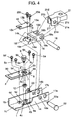
- the weight measuring equipment (hereafter referred to equipment) in the second preferred embodiment of the present invention will be described with reference to Fig. 4 to Fig. 9.
- U-shaped base 1 is fixed by bolt 51 to an object such as a chassis 50.
- Side plates 1a, 1b is provided with rotation support holes 16a, 16b for the support pin 22, and guide holes 17a, 17b for the link pin 18.
- Bottom plate 1c is provided with tapped holes 4a, 4b, 4c, 4d for fixing the strain detection substrate 2, and the relief hole 1d for threaded portion 9a of the fitting pin 9 and the nut 10.
- strain detection substrate 2 The structure, arrangement, and function of the strain detection substrate 2, the fitting pin 9, and the leaf spring 13 are the same as those in the first preferred embodiment.
- the arm 19 is provided with the hole 16, and is rotatably supported by the support pin 22 between the rotation support holes 16a, 16b formed in the side plates 1a, 1b of the base 1, which does not slip off due to threaded portion 22a formed at the end of the support pin 22, and the nut 23. Also, the wing portions 19a, 19b extending from one end of the arm 19 is respectively provided with slide holes 19c, 19d for guiding the link pin 18 so that the pin moves in the horizontal direction. Further, the projections 19e, 19f facing toward the bottom plate 1c of the base 1 are disposed at the end of the arm 19.
- the second arm 21 receives the load of the object to be measured and is vertically movable and is formed of U-shaped plate material.
- the link pin 18 goes through the holes 21c, 21d formed in the bent wing portions 21a, 21b of arm 21, the slide holes 19c, 19d of arm 19, and the guide holes 17a, 17b, or slots for guiding the pin vertically, disposed in the side plates 1a, 1b of the base 1.
- the link pin 18 is provided with an E-ring, which is not shown, to prevent the link pin 18 from slipping off.
- the wing portions 21a, 21b are partly provided with the projections 21e, 21f facing toward the bottom 1c of the base 1.
- the fitting pin 9 is fixed to the strain detection substrate 2 by using the nut 10.
- the strain detection substrate 2 is fixed to the base 1 with screws 5a, 5b, 5c, 5d.
- the leaf spring 13 is fixed to the arm 19 with screws 23a, 23b.
- the U-shaped notch 13c of the leaf spring 13 is inserted into the insert portion 9b of the fitting pin 9, and the arm 19 is supported by the support pin 22 on the base 1.
- the support pin 22 is fixed by nut 23.
- the slide holes 19c, 19d of the arm 19, the holes 21c, 21d of the arm 21, and the guide holes 17a, 17b of the base 1 are aligned to each other, through which the link pin 18 is inserted and attached to the arm 19, and an E-ring or the like is attached to prevent the pin from slipping off.
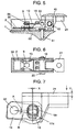
- Fig. 5 is a sectional view of the equipment completed as described above and mounted on a seat truck 45 of a vehicle seat and a chassis 50
- Fig. 6 is a plan view of the equipment.
- Lengthwise dimensions of the slide holes 19c, 19d are determined in anticipation of the X. Also, lengthwise dimensions of the guide holes 17a, 17b are determined taking into account of the stroke of arm 21. In this way, it is possible to reduce a detection error superposed on the load. The error occurs when a frictional force is generated on the slideway by an elastic repulsion due to the locus deviation, and the frictional force is superposed on the load. And it is also possible to reduce a hysteresis on a characteristic curve. In this way, a highly accurate equipment is obtained.
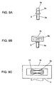
- the fitting pin 9 may have an arcuate inner wall at the insert portion 9b.
- the load acting portion is linearly concentrated, reducing the variation in acting position of the load transferred to the fitting pin 9, thereby improving the detection accuracy.
- the fitting pin 9 may have a semicircular inner wall at the insert portion 9b.
- the load acting portion is linearly concentrated, reducing the variation in acting position of the load transferred to the fitting pin 9, thereby improving the detection accuracy.
- the resultant effect is same as the fitting pin 9 shown in Fig. 8, but the detection accuracy is further improved because of suppressing the transfer of unnecessary load generated due to a distortion of the leaf spring 13.
- the wing portions 21a, 21b of the arm 21 are partly provided with the projections 21e, 21f facing toward the bottom plate 1c of the base 1 to prevent the leaf spring 13 and the strain detection substrate 2 from a permanent deformation or a breakdown when a load exceeding the maximum measuring load is applied to the arm 21.
- the projections 21e, 21f come into contact with the bottom plate 1c of the base 1.
- Fig. 10 is an exploded perspective view of the equipment.
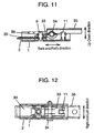
- Fig. 11 is a side sectional view of the equipment.
- Fig. 12 is a plan view of the equipment.
- wordings such as "up-and-down”, “back-and-forth” and “right-and-left”, they correspond to the directions of the arrows shown in Fig. 10.
- the structure, position, and function of base 1 fixed to an object (not shown), strain detection substrate 2, fitting pin 9 are same as those in the first preferred embodiment.
- the equipment of the present preferred embodiment includes a fixing pin 11 as a support portion of a leaf spring 33.
- the fixing pin 11 is made of a material that withstand a load higher than the measuring load, the same as the fitting pin 9.
- the fixing pin 11 is provided with a threaded portion 11a at an end portion, and an insert portion 11b at a hexagonal head portion, which is fixed in a tapped hole 12 of the base 1. Also, it is so configured that the insert portion 9b of fitting pin 9 and the insert portion 11b of fixing pin 11 are substantially same in height when the base 1 is attached with the strain detection substrate 2 including the fitting pin 9, and the fixing pin 11.
- a guide hole 33a for a shaft 34 is formed nearly in the middle of the leaf spring 33.
- a method of making the guide hole 33a it is preferable to employ a method of deformation processing of the leaf spring 33 as shown in Fig. 10 or a method of combination with other member (not shown).
- a dimension of the guide hole 33a with the shaft 34 inserted is made to be substantially free of play in the right-and-left, and the back-and-forth directions.
- U-shaped notches 33b, 33c at both ends of the leaf spring 33.
- the notches 33b, 33c are respectively inserted into the insert portion 9b of the fitting pin 9 and the insert portion 11b of the fixing pin 11 in such a manner that the pins are vertically immovable.
- the leaf spring 33 is designed to have spring charasteristics in accordance with the measuring load.
- Arm 35 as a movable member which receives the load of the object to be measured and is vertically movable is formed of U-shaped plate. Bent wing portions 35a, 35b are respectively provided with holes 35c, 35d so that the arm 35 is able to rotate on the shaft 34.
- the fitting pin 9 is fixed to the strain detection substrate 2 by the nut 10.
- the strain detection substrate 2 is fixed to the base 1 with screws 5a - 5d.
- the notched portion 33b and the notched portion 33c of leaf spring 33 are respectively inserted into the insert portion 9b of fitting pin 9 and the insert portion 11b of the fixing pin 11.
- the fixing pin 11 is fixed in the tapped hole 12 of the base 1.
- holes 35c, 35d and the guide hole 33a of the leaf spring 33 are aligned, and through which the shaft 34 is inserted, then the leaf spring 33 and the arm 35 are assembled via slots 26a, 26b formed in the side wall of the base 1, and the shaft 34 is fixed with nut 17.
- the leaf spring 13 suspended between the fitting pin 9 fixed to the strain detection substrate 2 and the fixing pin 11 fixed to the base 1 receives the load and deforms in a state of being supported at both end.
- a half of the weight of the object to be measured is applied to the action point of the strain detection substrate 2.
- a strain is generated in the detection substrate 2 in accordance with the load applied. Accordingly, a resistance of the strain resistor 8 changes, and the change of the resistance is computed in a processing circuit 30 to measure the load.
- the arm 35 is pulled upward, and the leaf spring 33 deforms upward, then a signal of opposite polarity is delivered from the strain detection substrate 2.
- the equipment is unitized, even when the equipment is built in various types of equipment, it is easy to assemble and possible to reduce the number of assembling steps, and it is unnecessary to adjust the sensor characteristics during the assembly.
- the above configuration involves no problem in the case of normal weight measurement, but when a load exceeding the maximum measuring load is applied to the equipment via the arm 35, the load is also applied to the leaf spring 33 and strain detection substrate 2. As a result, there is a possibility of a permanent deformation or damage of the leaf spring 33, or breakdown of the strain detection substrate 2. As a countermeasure, a possible method is to increase the withstand strength of the leaf spring 33 and the strain detection substrate 2. However, increasing the withstand strength of the leaf spring 33 causes the equipment to increase in size, and increasing the withstand strength of strain detection substrate 2 decreases the strain with respect to the load in the measuring range, resulting in lowering of the measuring resolution.
- slots 26a, 26b are formed in the side walls of the base 1.
- the slots 26a, 26b are longer in the up-and-down direction than a diameter of the shaft 34, the length of which is set so as to allow the shaft 34 to be movable in the up-and-down direction for an amount of maximum deformation of the leaf spring 33 at a maximum measuring load applied.
- the shaft 34 comes in contact with the inner walls of slots 26a, 26b, and stops. Accordingly, even when a load or impact load higher than the maximum measuring load is applied, the stopper structure receives the load, and thereby, it is possible to prevent the breakdown of the strain detection substrate 2 or the leaf spring 33.
- the dimensions in the widthwise direction (right-and-left direction in Fig. 10) and lengthwise direction (back-and-forth direction in Fig. 10) of the notches 33b, 33c formed in both ends of the leaf spring 33 are set larger than the diameters of the insert portion 9b of fitting pin 9 and the insert portion 11b of fixing pin 11.
- the purpose is to prevent a force from being directly applied to the insert portion 9b of fitting pin 9 when an abnormal force is applied back-and-forth and right-and-left direction, during the measurement or standby mode to the object to be measured, to the equipment, and to the mounting object.
- the load applied is 2,000 kg or more.
- the equipment is designed not to break down owing to the withstand strength of the shaft 34 and the base 1, in the course of the impact application, the impact is absorbed by a little destortions of the shaft 34 and other structures.
- the dimensions of the notches 33b, 33c of the leaf spring 33 is decided so as to provide a clearance in accordance with such distortions.
- Fig. 13 is an exploded perspective view showing an essential portion of the equipment in the present preferred embodiment.
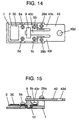
- Fig. 14 is a plan view of the equipment of the present preferred embodiment.
- Fig. 15 is a side sectional view of the equipment of the present preferred embodiment.
- Figs. 16A and 16B are a front view and a side sectional view of a fitting pin showing another configuration in the present preferred embodiment.
- Figs. 17A and 17B are a front view and a side sectional view of a fitting pin showing still another configuration of the present preferred embodiment.
- the base 1 fixed to an object such as chassis 50 is provided with tapped holes 4a, 4b, 4c, 4d for fixing the strain substrate 2, and tapped holes 12a, 12b for fixing leaf spring 43 at positions higher than the tapped holes 4a through 4d.
- the structure, arrangement, and function of the strain detection substrate 2 are the same as those in the first preferred embodiment.
- Fitting pin 9 is made of a material capable of withstanding a load higher than the measuring load, and is provided with a threaded portion 9a at the lower part, and a insert portion 9b at a head thereof. Also, the fitting pin 9 is inserted into the hole 6 of strain detection substrate 2 and fixed by a nut 10.
- a leaf spring 43 is made of a material capable of withstanding a load higher than the measuring load as the same as the fitting pin 9, and a middle beam 43c at a tip end portion thereof is inserted into the insert portion 9b of the fitting pin 9 and is held therein. Also, fixing holes 43a, 43b are formed in end beams 43e, 43f at both sides of the leaf spring 43 which is fixed by screws 28a, 28b to the tapped holes 12a, 12b of the base 1. The insert portion 9b of fitting pin 9 and the middle beam 43c of the leaf spring 43 are substantially same in height. Also, at another end portion of the leaf spring 43 is formed fixing hole 43d as a load input portion to be attached to the object to be measured.
- the fitting pin 9 is fixed to the strain detection substrate 2 by the nut 10.
- the strain detection substrate 2 is fixed to the base 1 with screws 5a, 5b, 5c, 5d.
- the middle beam 43c of the leaf spring 43 is inserted into the insert portion 9b of the fitting pin 9, and is the leaf spring 43 fastened to the tapped holes 12a, 12b of the base 1 by screws 28a, 28b through fixing holes 43a, 43b.
- the end portion of the leaf spring 43 is fork-shaped and only the middle beam 43c is held by the fitting pin 9, and therefore, a load reduced at a specific ratio against the input load is applied to the strain detection substrate 2. Also, it is possible to reduce the load applied to the strain detection substrate 2 at a specific ratio by changing a length of notched portions or a width of the middle beam 43c of the fork-shaped portion of the leaf spring 43, or by properly changing a distance from the fixing holes 43a, 43b of the end beams 43e, 43f at both side ends of leaf spring 43 to the fitting pin 9.
- a contacting portion between the inner wall formed in the insert portion 9b of the fitting pin 9 and the middle beam 43c of leaf spring 43 becomes a line ora point. Therefore, it is possible to reduce a friction between the two components and also to suppress a transfer of unnecessary load generated due to a twisting or the like. As a result, the stability of the sensor output against the load may be further enhanced.
- the equipment of the present preferred embodiment is unitized, when the equipment is attached to a vehicle seat, for example, it is possible to reduce the number of assembling steps and it is unnecessary to adjust the sensor characteristics during assembly.
- Fig. 18 is an exploded perspective view of the equipment in the present preferred embodiment.
- Fig. 19 is a plan view of the equipment.
- Fig. 20 is a side sectional view.
- Figs. 21A, 21B are a front view and a side view of a fitting pin showing another configuration in the present preferred embodiment.
- Figs. 22A, 22B are a front view and a side view of a fitting pin showing still another configuration of the present preferred embodiment.
- the middle beam 43c of the leaf spring 43 in the fourth preferred embodiment 4 is divided into U-shape, while the insert portion 9b of the fitting pin 9 is H-shaped in section. This configuration makes it easier to hold the middle beam 43c on the fitting pin 9, and simplifies the shape of the fitting pin 9, thereby improving the workability.
- the inner walls of the insert portion 9b of fitting pin 9 arcuate in shape as shown in Figs. 21A and 21B, or semicircular as shown in Figs. 22A and 22B.
- Fig. 23 is an exploded perspective view showing the sixth preferred embodiment.
- Fig. 24 is a plan view, and Fig. 25 is a side sectional view of the equipment.
- a load input end side of leaf spring 43 is divided into three portions, and side holding portion 43g, 43h and middle holding portion 43i are bent opposite to each other so that the leaf spring 43 can be held by link pin 38.
- arm 39 having fixing hole 39c to be attached to a load applied portion, which is suspended by the link pin 38 via holes 39a, 39b.
- slots 27a, 27b are formed in the side walls of the base 1 for vertically guiding the link pin 38 and for controlling an amount of distortion of the leaf spring pin 43.
- the arm 39 to which a weight of the object to be measured is applied is supported by the link pin 38, the arm 39 always receive the load in a parallel state, and can correctly transfer the load to the strain detection substrate 2 via the leaf spring 43.
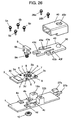
- Fig. 26 is an exploded perspective view showing the present preferred embodiment.
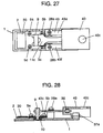
- Fig. 27 is a plan view, and Fig. 28 is a side sectional view of the equipment.
- a load input end side of leaf spring 43 is provided with a semicircular projection 36.
- An arm 40 is substantially box-shaped, and at a top thereof is formed a hole 40c to be attached to a load applied portion.
- V-shaped ribs 37a, 37b are provided at an end portion of the base 1.
- the arm 40 holds the semicircular projection 36 formed on the leaf spring 43 in such manner as to enclose the semicircular projection 36, and is disposed in a substantially parallel arrangement to the V-shaped ribs 37a, 37b provided at the end portion of the base 1.
- a clearance is provided between the bottom inner surface of arm 40 and the ribs 37a, 37b for an amount of maximum displacement of the leaf spring 43 for the maximum measuring load against an upper displacement of the arm 40 in the up-and-down direction. Also, a clearance is provided between a bottom outer surface of arm 40 and the base surface of base 1 for an amount of maximum displacement of the leaf spring 43 for the maximum measuring load against the lower displacement of the arm 40 in the up-and-down direction.
- the stopper structure receives the load, protecting the strain detection substrate 2 from excessive load, and prevents the breakdown of the strain detection substrate 2 and the leaf spring 43.
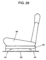
- Fig. 29 is a side view for describing a vehicle seat attached with any one of the equipments shown in Fig. 1, Fig. 4, Fig. 10, Fig. 13, Fig. 18, Fig. 23 and Fig. 26.
- a seat truck 45 is disposed beneath a seat (such as a passenger seat) 46.
- the load input end side of the equipment 44 of the present invention is attached by bolts and nuts (not shown) to the seat truck 45.
- the base 1 of the equipment 44 is similarly fixed by bolts and nuts (not shown) to chassis 50.
- the equipments 44 are disposed at a front and a rear ends of the seat trucks 45 so as to correspond to the four bottom comers of the seat 46. In this condition, the weight of the person actually sitting on the seat 46 is measured by the equipments 44 disposed at four portions and computed to judge the weight. At the time, a weight of the seat 46 itself is compensated by previously setting or storing in a memory.
- the equipments 44 are disposed at the front and the rear ends of the seat trucks 45 in such manner as to correspond to the four bottom comers of the seat 46, it is possible to judge the weight even when the position of the person sitting on the seat is changed, and also, to estimate the sitting position by comparing the loads.
- the number of the equipments disposed is not limit to four. It is also preferable to install one or two equipments at a side opposite to the front or rear support portion of the seat which is rotatably supported, and further, to increase the number of the equipments disposed in order to improve a measuring accuracy.
- the present invention it is possible to obtain a weight measuring equipment reduced in a load applied to the strain detection substrate and improved in detecting resolution. Also, since the weight measuring equipment is unitized, it can be easily built in various types of equipment including seats for vehicles.
Landscapes
- Engineering & Computer Science (AREA)
- Physics & Mathematics (AREA)
- Mathematical Physics (AREA)
- Theoretical Computer Science (AREA)
- Mechanical Engineering (AREA)
- Aviation & Aerospace Engineering (AREA)
- Transportation (AREA)
- General Physics & Mathematics (AREA)
- Measurement Of Force In General (AREA)
- Force Measurement Appropriate To Specific Purposes (AREA)
Abstract
Description
Claims (23)
- A weight measuring equipment comprising:a base fixed to an object to be mounted;a strain detection substrate attached to said base;a fitting pin fixed to said strain detection substrate;an arm rotatably attached to said base by a support pin; anda leaf spring, said leaf spring fixed with one end to said arm and supported with another end by said fitting pin.
- The weight measuring equipment of claim 1, further comprising a second arm, said second arm receiving a load of an object to be measured with one end, and fixed to said arm by a link pin with another end.
- The weight measuring equipment of claim 1, wherein a part of one of said arm and said second arm comes into contact with said base when a load exceeds a maximum measuring load of said weight measuring equipment.
- The weight measuring equipment of claim 1, wherein said leaf spring is provided with a predetermined clearance from said fitting pin at a portion supported by said fitting pin.
- The weight measuring equipment of claim 2, wherein
said link pin is supported by a guide hole to be movable in a direction perpendicular to a bottom of said base, said guide hole formed in said base, and
said link pin is supported by a slide hole to be movable in a direction parallel to the bottom of said base, said slide hole formed in said arm. - The weight measuring equipment of claim 1, wherein an inner wall of said fitting pin at a portion for supporting said leaf spring has one of arcuate shape and semicircular shape.
- The weight measuring equipment of claim 1, further comprising a fixing pin fixed to said base, wherein
said leaf spring is supported by said fitting pin and said fixing pin at both ends thereof, and
said arm is connected nearly to a middle portion of said leaf spring and is movable in up-and-down direction by receiving a weight of an object to be measured. - The weight measuring equipment of claim 7, wherein said leaf spring is provided with a predetermined clearance from said fixing pin at a portion supported by said fixing pin.
- The weight measuring equipment of claim 7, wherein a shaft which supports said leaf spring is movable in up-and-down direction in a slot formed in said base.
- The weight measuring equipment of claim 7, wherein said shaft comes into contact with an inner wall of said slot when a load exceeds a maximum measuring load of said weight measuring equipment.
- The weight measuring equipment of claim 1, wherein
said leaf spring is provided with fork-shaped three beams at one end, and another end of said leaf spring is a load applied portion for receiving a load,
said fitting pin has an insert portion for holding a middle beam of said three beams, and
ends of the beams at both sides of said three beams are fixed to said base, respectively. - The weight measuring equipment of claim 11, wherein the middle beam of said leaf spring held by said fitting pin is one of straight and divided in shape.
- The weight measuring equipment of claim 11, wherein said middle beam is narrower in width than the beams at both sides.
- The weight measuring equipment of claim 11, wherein a inner wall of a portion for supporting said middle beam of said fitting pin is one of arcuate and semicircular in shape.
- The weight measuring equipment of claim 11, wherein
the load applied portion side of said leaf spring is divided into three portions, both of side portions and middle portion of said three portions divided being bent opposite to each other and held by a link pin, and
said link pin supports an arm provided with a fixing hole for the load applied portion. - The weight measuring equipment of claim 11, wherein a semicircular projection is disposed at the load applied portion side of said leaf spring, and said arm is arranged so as to hold said semicircular projection.
- The weight measuring equipment of claim 11, wherein a stopper for controlling an amount of deformation of said leaf spring is provided.
- The weight measuring equipment of claim 1, wherein
said base is fixed to the chassis side of a vehicle, and
one of said arm and said second arm is connected to a seat truck bottom of a vehicle seat. - The weight measuring equipment of claim 1, wherein said base is fixed to a seat truck of a vehicle seat, and one of said arm and said second arm is connected to the vehicle seat.
- Person weight measuring equipment comprising the the weight measuring equipment of any one of claims 1 through 19, the base of said weight measuring equipment being fixed to a chassis side, and
one of the arm and the second arm of said weight measuring equipment being fixed to a seat truck bottom of a vehicle seat,
wherein a seat weight seat and person weight is measured by a load detected by said weight measuring equipment. - The person weight measuring equipment of claim 20, wherein said weight measuring equipment is installed at four comers of said vehicle seat.
- Person weight measuring equipment comprising the the weight measuring equipment of any one of claims 1 through 19, the base of said weight measuring equipment being fixed to a seat truck of a vehicle seat, and
one of the arm and the second arm of said weight measuring equipment being fixed to said vehicle seat,
wherein a seat weight seat and person weight is measured by a load detected by said weight measuring equipment. - The person weight measuring equipment of claim 22, wherein said weight measuring equipment is installed at four corners of said vehicle seat.
Applications Claiming Priority (7)
| Application Number | Priority Date | Filing Date | Title |
|---|---|---|---|
| JP2001116599A JP2002310779A (en) | 2001-04-16 | 2001-04-16 | Weight measuring device and seat weight measuring device using the same |
| JP2001116599 | 2001-04-16 | ||
| JP2002036497A JP3680798B2 (en) | 2002-02-14 | 2002-02-14 | Weight measuring device and seat weight measuring device using the same |
| JP2002036497 | 2002-02-14 | ||
| JP2002039504 | 2002-02-18 | ||
| JP2002039504A JP3680800B2 (en) | 2002-02-18 | 2002-02-18 | Weight measuring device and seat weight measuring device using the same |
| PCT/JP2002/003720 WO2002084233A1 (en) | 2001-04-16 | 2002-04-15 | Weight measuring equipment and crew weight measuring equipment comprising it |
Publications (2)
| Publication Number | Publication Date |
|---|---|
| EP1380819A1 true EP1380819A1 (en) | 2004-01-14 |
| EP1380819A4 EP1380819A4 (en) | 2010-10-06 |
Family
ID=27346537
Family Applications (1)
| Application Number | Title | Priority Date | Filing Date |
|---|---|---|---|
| EP02717149A Withdrawn EP1380819A4 (en) | 2001-04-16 | 2002-04-15 | WEIGHT MEASURING EQUIPMENT AND EQUIPMENT WEIGHT MEASURING APPARATUS INCLUDING EQUIPMENT |
Country Status (4)
| Country | Link |
|---|---|
| US (1) | US6916998B2 (en) |
| EP (1) | EP1380819A4 (en) |
| CA (1) | CA2413082C (en) |
| WO (1) | WO2002084233A1 (en) |
Families Citing this family (2)
| Publication number | Priority date | Publication date | Assignee | Title |
|---|---|---|---|---|
| JP2004317400A (en) * | 2003-04-18 | 2004-11-11 | Takata Corp | Seat load measuring apparatus |
| JP2005249598A (en) * | 2004-03-04 | 2005-09-15 | Denso Corp | Load detection device |
Family Cites Families (6)
| Publication number | Priority date | Publication date | Assignee | Title |
|---|---|---|---|---|
| DE2915553C2 (en) * | 1979-04-18 | 1981-04-02 | Bizerba-Werke Wilhelm Kraut Kg, 7460 Balingen | Device for introducing a force to be measured into a bending rod |
| JP4079479B2 (en) | 1997-06-13 | 2008-04-23 | タカタ株式会社 | Vehicle seat device and airbag device |
| JP4585054B2 (en) | 1999-03-09 | 2010-11-24 | タカタ株式会社 | Seat weight measuring device |
| JP2001108513A (en) * | 1999-09-21 | 2001-04-20 | Takata Corp | Seat load measuring device |
| US6448512B1 (en) * | 2000-08-22 | 2002-09-10 | Trw Inc. | Weight sensing apparatus |
| JP3904913B2 (en) * | 2001-12-18 | 2007-04-11 | 株式会社タチエス | Load detection structure for vehicle seat |
-
2002
- 2002-04-15 WO PCT/JP2002/003720 patent/WO2002084233A1/en not_active Ceased
- 2002-04-15 US US10/311,474 patent/US6916998B2/en not_active Expired - Fee Related
- 2002-04-15 EP EP02717149A patent/EP1380819A4/en not_active Withdrawn
- 2002-04-15 CA CA002413082A patent/CA2413082C/en not_active Expired - Fee Related
Also Published As
| Publication number | Publication date |
|---|---|
| CA2413082C (en) | 2007-04-10 |
| US20040094337A1 (en) | 2004-05-20 |
| EP1380819A4 (en) | 2010-10-06 |
| CA2413082A1 (en) | 2002-12-13 |
| US6916998B2 (en) | 2005-07-12 |
| WO2002084233A1 (en) | 2002-10-24 |
Similar Documents
| Publication | Publication Date | Title |
|---|---|---|
| US6069325A (en) | Seat weight measuring apparatus | |
| US6448512B1 (en) | Weight sensing apparatus | |
| US6859753B1 (en) | Apparatus and method for measuring the weight of an occupant in a vehicle | |
| JP2002166768A (en) | Load detection structure for vehicle seats | |
| JP2001108513A (en) | Seat load measuring device | |
| JP2002168682A (en) | Load detection structure for vehicle slide seat | |
| JP5232390B2 (en) | Elevator load detection device | |
| EP1202032B1 (en) | Fixing structure for sensing element | |
| US20030067196A1 (en) | Attachment structure of a load sensor for a vehicle seat | |
| US6835899B2 (en) | Load sensing assembly for a vehicle seat | |
| US7000488B2 (en) | Force-sensing unit for measuring a belt tensile force acting on a seatbelt lock | |
| CA2413082C (en) | Weight measuring device and person weight measuring equipment including the weight measuring device | |
| US6508514B2 (en) | Parallelogram load sensing apparatus for a vehicle seat | |
| US6732593B2 (en) | Attachment structure of a load sensor for a vehicle seat | |
| JP3797376B2 (en) | Seat load detection device | |
| US7360460B2 (en) | Sensor device for a vehicle seat | |
| EP0955203B1 (en) | Load sensing mounting for a vehicle seat | |
| US7061389B2 (en) | Seat weighing device | |
| JP3680800B2 (en) | Weight measuring device and seat weight measuring device using the same | |
| JP4599986B2 (en) | Seat load detection device | |
| JP2006513893A5 (en) | ||
| JP2007057425A (en) | Seat load detector | |
| JP3680798B2 (en) | Weight measuring device and seat weight measuring device using the same | |
| KR20030077038A (en) | Device for receiving a force acting upon a vehicle seat | |
| JP2005037356A (en) | Seat weight measuring device |
Legal Events
| Date | Code | Title | Description |
|---|---|---|---|
| PUAI | Public reference made under article 153(3) epc to a published international application that has entered the european phase |
Free format text: ORIGINAL CODE: 0009012 |
|
| 17P | Request for examination filed |
Effective date: 20030114 |
|
| AK | Designated contracting states |
Kind code of ref document: A1 Designated state(s): AT BE CH CY DE DK ES FI FR GB GR IE IT LI LU MC NL PT SE TR |
|
| RIN1 | Information on inventor provided before grant (corrected) |
Inventor name: KAWASAKI, SHUSAKU Inventor name: YOSHIUCHI, SHIGEHIRO Inventor name: TANAKA, TSUYOSHI Inventor name: SAITO, KIYOSHI |
|
| RAP1 | Party data changed (applicant data changed or rights of an application transferred) |
Owner name: PANASONIC CORPORATION |
|
| A4 | Supplementary search report drawn up and despatched |
Effective date: 20100903 |
|
| STAA | Information on the status of an ep patent application or granted ep patent |
Free format text: STATUS: THE APPLICATION IS DEEMED TO BE WITHDRAWN |
|
| 18D | Application deemed to be withdrawn |
Effective date: 20101202 |