EP1380786A1 - Clamp for holding elongated article - Google Patents
Clamp for holding elongated article Download PDFInfo
- Publication number
- EP1380786A1 EP1380786A1 EP03009878A EP03009878A EP1380786A1 EP 1380786 A1 EP1380786 A1 EP 1380786A1 EP 03009878 A EP03009878 A EP 03009878A EP 03009878 A EP03009878 A EP 03009878A EP 1380786 A1 EP1380786 A1 EP 1380786A1
- Authority
- EP
- European Patent Office
- Prior art keywords
- clamp
- elastic stop
- elongated article
- stop member
- sidewalls
- Prior art date
- Legal status (The legal status is an assumption and is not a legal conclusion. Google has not performed a legal analysis and makes no representation as to the accuracy of the status listed.)
- Granted
Links
- 230000037431 insertion Effects 0.000 claims abstract description 52
- 238000003780 insertion Methods 0.000 claims abstract description 52
- 238000005452 bending Methods 0.000 claims abstract description 10
- 238000000605 extraction Methods 0.000 description 2
- 230000001419 dependent effect Effects 0.000 description 1
- 238000001746 injection moulding Methods 0.000 description 1
Images





Classifications
-
- F—MECHANICAL ENGINEERING; LIGHTING; HEATING; WEAPONS; BLASTING
- F16—ENGINEERING ELEMENTS AND UNITS; GENERAL MEASURES FOR PRODUCING AND MAINTAINING EFFECTIVE FUNCTIONING OF MACHINES OR INSTALLATIONS; THERMAL INSULATION IN GENERAL
- F16L—PIPES; JOINTS OR FITTINGS FOR PIPES; SUPPORTS FOR PIPES, CABLES OR PROTECTIVE TUBING; MEANS FOR THERMAL INSULATION IN GENERAL
- F16L3/00—Supports for pipes, cables or protective tubing, e.g. hangers, holders, clamps, cleats, clips, brackets
- F16L3/08—Supports for pipes, cables or protective tubing, e.g. hangers, holders, clamps, cleats, clips, brackets substantially surrounding the pipe, cable or protective tubing
- F16L3/12—Supports for pipes, cables or protective tubing, e.g. hangers, holders, clamps, cleats, clips, brackets substantially surrounding the pipe, cable or protective tubing comprising a member substantially surrounding the pipe, cable or protective tubing
- F16L3/13—Supports for pipes, cables or protective tubing, e.g. hangers, holders, clamps, cleats, clips, brackets substantially surrounding the pipe, cable or protective tubing comprising a member substantially surrounding the pipe, cable or protective tubing and engaging it by snap action
-
- F—MECHANICAL ENGINEERING; LIGHTING; HEATING; WEAPONS; BLASTING
- F16—ENGINEERING ELEMENTS AND UNITS; GENERAL MEASURES FOR PRODUCING AND MAINTAINING EFFECTIVE FUNCTIONING OF MACHINES OR INSTALLATIONS; THERMAL INSULATION IN GENERAL
- F16L—PIPES; JOINTS OR FITTINGS FOR PIPES; SUPPORTS FOR PIPES, CABLES OR PROTECTIVE TUBING; MEANS FOR THERMAL INSULATION IN GENERAL
- F16L3/00—Supports for pipes, cables or protective tubing, e.g. hangers, holders, clamps, cleats, clips, brackets
- F16L3/22—Supports for pipes, cables or protective tubing, e.g. hangers, holders, clamps, cleats, clips, brackets specially adapted for supporting a number of parallel pipes at intervals
-
- F—MECHANICAL ENGINEERING; LIGHTING; HEATING; WEAPONS; BLASTING
- F16—ENGINEERING ELEMENTS AND UNITS; GENERAL MEASURES FOR PRODUCING AND MAINTAINING EFFECTIVE FUNCTIONING OF MACHINES OR INSTALLATIONS; THERMAL INSULATION IN GENERAL
- F16L—PIPES; JOINTS OR FITTINGS FOR PIPES; SUPPORTS FOR PIPES, CABLES OR PROTECTIVE TUBING; MEANS FOR THERMAL INSULATION IN GENERAL
- F16L3/00—Supports for pipes, cables or protective tubing, e.g. hangers, holders, clamps, cleats, clips, brackets
- F16L3/22—Supports for pipes, cables or protective tubing, e.g. hangers, holders, clamps, cleats, clips, brackets specially adapted for supporting a number of parallel pipes at intervals
- F16L3/223—Supports for pipes, cables or protective tubing, e.g. hangers, holders, clamps, cleats, clips, brackets specially adapted for supporting a number of parallel pipes at intervals each support having one transverse base for supporting the pipes
Definitions
- the invention relates to an improvement of a clamp for holding an elongated article having a linear shape, a bar shape or a tubular shape at an intermediate portion thereof.
- a clamp for holding an elongated article includes an insertion concave portion for receiving the elongated article and elastic stop members projecting toward a bottom of the insertion concave portion.
- the elastic stop members hold the elongated article at lower ends of the elastic stop members with elastic force, as the elongated article is inserted in the insertion concave portion.
- the insertion force can be reduced.
- the lower end of the elastic stop member contacting the elongated article becomes shorter, it is difficult to increase the extraction force.
- the insertion force can be reduced, and, at the same time, a whole length of the lower ends of the elastic stop members (a total length of the lower ends of the respective divided elastic stop members) contacting the elongated article can be made longer.
- the total length of the lower ends essentially becomes shorter due to a space between the adjacent elastic stop members as compared to a non-divided elastic stop member.
- the respective divided elastic stop members need to have uniform rigidity. Otherwise, it is difficult to hold the elongated article stably.
- an object of the invention is to provide a clamp in which a lower end of an elastic stop member for holding the elongated article has a sufficient length, while an elongated article is inserted into the clamp portion with a minimum force.
- a clamp for holding an elongated article includes at least one clamp portion having an insertion concave portion for receiving the elongated article and at least one elastic stop member.
- the insertion concave portion has a pair of sidewalls along a longitudinal direction of the elongated article to be inserted.
- the elastic stop member has an upper end integrally joined to an upper portion of the sidewall constituting the insertion concave portion, and projects diagonally downward toward a bottom of the insertion concave portion.
- the clamp portion holds the elongated article such that a lower end of the elastic stop member elastically holds the elongated article at an insertion position under the lower end of the elastic stop member.
- At least one space is formed at a joining portion of the upper end of the elastic stop member and the sidewall, so that a total length of the joining portion as a bending center of the elastic stop member along the longitudinal direction of the elongated article becomes smaller than a total length of the lower end of the elastic stop member along the longitudinal direction of the elongated article.
- the lower end of the elastic stop member has a long contact length relative to the elongated article.
- the elongated article can be held with a greater force while it is possible to insert the elongated article into the clamp portion with a smaller force.
- the clamp for holding the elongated article according to the first aspect includes an attaching portion with respect to an object to be attached.
- the clamp is attached to the object using the attaching portion while the clamp portion holds the elongated article so that the elongated article can be attached to the object.
- the clamp for holding the elongated article according to the first aspect includes more than two clamp portions disposed in parallel.
- the clamp can hold more than two elongated articles in a state that the elongated articles are bundled. Also, the respective elongated articles can be positioned at predetermined positions relative to each other.
- a plurality of the elastic stop members is integrated with both of the sidewalls. Further, at lease one space is formed at a joining portion between at least one of the pair of the sidewalls and the upper end of the elastic stop member.
- more than two elastic stop members with a space therebetween are provided in a longitudinal direction of the elongated article. At least one of the elastic stop members has an end portion at a level different from those of the other elastic stop members.
- the elastic stop member having the lower end located at a lower level toward the bottom of the insertion concave portion holds the elongated article having a smaller diameter.
- the elastic stop member having the lower end located at a higher level holds the elongated article having a larger diameter.
- the space is formed of a notch portion provided at the joining portion of the upper end of the elastic stop member and the sidewall.
- the total length of the joining portion as a bending center of the elastic stop member along the longitudinal direction of the elongated article can be made shorter than that of the lower end of the elastic stop member along the longitudinal direction of the elongated article.
- the space is formed at upper portions of a connection member connecting the lower ends of the elastic stop members.
- a total length of the joining portion as a bending center of the elastic stop members along the longitudinal direction of the elongated article can be made shorter than that of the lower ends of the elastic stop members along the longitudinal direction of the elongated article.
- each of the elastic stop members can be bent independently. Thus, it is possible to reduce the force for inserting the elongated article into the insertion concave portion. At the same time, the connection member or the lower ends of the elastic stop members effectively prevent the elongated article from moving out.
- a clamp K for holding an elongated article H includes at least one clamp portion 1 to hold the elongated article H having a linear shape, a bar shape or a pipe shape, at an intermediate portion of the article.
- the clamp portion 1 described above is formed of an insertion concave portion 2 for the elongated article H and elastic stop members 4.
- the insertion concave portion 2 includes a pair of sidewalls 3 along a longitudinal direction of the elongated article H to be inserted therein. More specifically, in the insertion concave portion 2, an upper side between the pair of the sidewalls 3 is open, and one side of the pair of the sidewalls 3 and the other side of the pair of the sidewalls 3 are formed in a groove shape opened sideward. The elongated article H is inserted into the insertion concave portion 2 from the upper side of the pair of the sidewalls 3.
- the elastic stop members 4 have upper ends integrally connected to an upper portion of at least one of the pair of the sidewalls 3 constituting the insertion concave portion 2. Each elastic stop member 4 projects obliquely downward toward a bottom of the insertion concave portion 2. In other words, the elastic stop member 4 is attached to the sidewall 3 so that the distance between the sidewall 3 and the elastic stop member 4 is gradually widened from the upper end to a lower end of the elastic stop member 4.
- the lower ends 4a of the elastic stop members 4 hold the elongated article H with an elastic force at an insertion position under the lower ends 4a, when the elongated article H is inserted.
- the elastic stop members 4 are pressed against the elongated article H to thereby bend toward the sidewall 3 to which the elastic stop members 4 are attached.
- the elongated article H is then inserted into a space between the lower ends 4a of the elastic stop members 4 and the bottom of the insertion concave portion 2 corresponding to a diameter of the elongated article H.
- At least one space 7 is formed at a joining portion of the upper end of the elastic stop member 4 and the sidewall 3. With this space 7, a total length of a portion 6, which is a center of bending the elastic stop member 4, along the longitudinal direction of the elongated article H becomes shorter than a total length of the lower ends 4a of the elastic stop members 4 along the longitudinal direction of the elongated article H.
- the elastic stop member 4 is easily bent when the elongated article H is inserted into the insertion concave portion 2.
- the lower ends 4a of the elastic stop members 4 contact the elongated article H at a long contact line.
- the insertion force is small.
- the space 7 may be formed of a notch at the joining portion 5 of the upper end of the elastic stop member 4 and the sidewall 3.
- a total length of the portion 6, which is a central portion of bending the elastic stop member 4, along the longitudinal direction of the elongated article H becomes shorter than a total length of the lower ends 4a of the elastic stop members 4 along the longitudinal direction of the elongated article H.
- the space 7 may be formed at upper portions of connection members connecting lower ends of more than two units constituting the elastic stop member 4.
- a total length of the portion 6, which is a central portion of bending the elastic stop member 4, along a longitudinal direction of the elongated article H becomes shorter than a total length of the lower ends 4a of the elastic stop members 4 along the longitudinal direction of the elongated article H.
- such a space 7 may be formed in a slot portion 7a extending between the upper end of the elastic stop member 4 and the upper portion of the sidewall 3 at the joining portion 5.
- the space 7 is formed in a window hole portion 7b with a sidewall 3 as a window upper edge and having an opening at the upper end of the elastic stop member 4.
- the space 7 In the case that the space 7 is formed as shown in Fig. 13, the space 7 does not lower the rigidity of the sidewall 3. Thus, the clamp portion 1 easily holds the elongated article H with a large force.
- the total length of the portion 6, which is the center of bending the elastic stop member 4, in the longitudinal direction of the elongated article H becomes shorter relative to those of the lower ends 4a of the elastic stop members 4 in the longitudinal direction of the elongated article H.
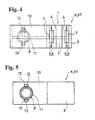
- Figs. 1 to 7 show an example of the clamp K1 including the clamp portion 1.
- the clamp K1 according to the first embodiment includes one clamp portion 1.
- the elastic stop members 4 are provided in the pair of the sidewalls 3 constituting the insertion concave portion 2.
- the elastic stop members 4 are provided along a direction extending from the sidewalls 3.
- the spaces 7 having a long hole shape are formed in the upper ends of the elastic stop members 4 along the direction extending from the sidewalls 3.
- the spaces 7 are provided in the elastic stop members 4 disposed on one of the pair of the sidewalls 3 and the other of the pair of the sidewalls 3, respectively.
- the elastic stop members 4 are easily bent due to the spaces 7 when the elongated article H is inserted into the insertion concave portion 2 to thereby lower the force of inserting the elongated article H.
- the lower ends 4a of the elastic stop members 4 are pressed against the elongated article H, thereby securely holding the elongated article H in the insertion concave portion 2.
- the clamp K1 includes an attaching portion 8 for attaching the elongated article H to an object P to be attached. While the clamp portion 1 holds the elongated article H, the clamp is attached to the object P to be attached through the attaching portion 8. Thus, in the present embodiment, the elongated article H can be held by the object P to be attached through the clamp K1.
- the attaching portion 8 is provided on one side of a base plate 10 having one end integrally connected to a main portion 9 constituting the clamp portion 1.
- the attaching portion 8 includes a cylindrical member 11 having one end integrally fixed to a surface of the base plate 10 opposite to an entrance of the insertion concave portion 2 and projecting from the surface of the base plate 10; elastic pieces 12 disposed at both sides in a radial direction of the cylindrical member 11 in a state that the elastic pieces can bend toward an inner direction of the cylindrical member 11 and having forward ends positioned on a base portion of the cylindrical member 11; and engaging projections 13 provided outside the forward ends of the elastic pieces 12.
- an attaching hole Pa with a diameter slightly smaller than a distance between top ends of the engaging projections 13 of the elastic pieces 12 is formed on the object P to be attached.
- the elastic pieces 12 are bent inward as the cylindrical member 11 is inserted into the attaching hole Pa. Accordingly, the engaging projections 13 engage an edge of the attaching hole with an elastic force of the elastic pieces 12 in a state where the cylindrical member 11 enters the attaching hole Pa, thereby attaching the clamp K1 to the object P to be attached through one-step operation (see Fig. 1)
- Fig. 8 is a view schematically showing another example, i.e. a clamp K2, including the clamp portions 1.
- the clamp K2 has more than two clamp portions 1.
- the elastic stop members 4 are provided to one of the pair of the sidewalls 3 constituting the insertion concave portions 2.
- Each elastic stop member 4 is provided along the direction extending from the sidewall 3.
- the spaces 7 are formed in the upper ends of the elastic stop members 4, respectively.
- the clamp portions 1 are disposed in parallel. Specifically, the clamp portions 1 are provided so that the sidewalls 3 constituting the insertion concave portions 2 of the clamp portions 1 are arranged substantially in parallel with each other, thereby constituting the clamp K2 with more than two clamp portions 1.
- more than two elongated articles H can be held by the clamp portions 1 and be bundled up through the clamp K2. Also, the elongated articles H to be bundled together can be disposed at their predetermined positions.
- Fig. 9 is a view schematically showing another example, i.e. a clamp K3, including the clamp portions 1.
- the clamp K3 according to the embodiment may include more than two clamp portions 1.
- the elastic stop members 4 are provided to the pair of the sidewalls 3, 3 constituting the insertion concave portions 2, respectively.
- Each elastic stop member 4 is provided along the direction extending from the sidewall 3.
- the space 7 is formed in the upper end of each elastic stop member 4.
- the clamp portions 1 are disposed in parallel.
- the clamp portions 1 are provided so that the sidewalls 3 constituting the insertion concave portions 2 of the clamp portions 1 are arranged substantially in parallel with each other, thereby constituting the clamp K3 having two clamp portions 1 in parallel.
- two elongated articles H can be held by the clamp portions 1 and be bundled up through the clamp K3. Also, the elongated articles H bundled together can be disposed at their predetermined positions.
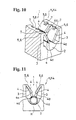
- Figs. 10 to 12 are views schematically showing another example, i.e. a clamp K4, including the clamp portion 1, and also showing a portion where the clamp portion 1 of the clamp K4 is provided.
- the clamp portion 1 is provided with more than two elastic stop members 4, with a space therebetween in the longitudinal direction of the elongated article H.
- two elastic stop members 4 are provided in each of the pair of the sidewalls 3 constituting the insertion concave portion 2 along the longitudinal direction of the elongated article H with a space therebetween.
- the respective elastic stop members 4 are disposed along the direction extending from the sidewalls 3.
- the spaces 7 are formed in the upper ends of the respective elastic stop members 4.
- At least one set of the elastic stop members 4 has lower ends 4a situated at a level different from those of lower ends 4a of another set of the elastic stop members 4.
- the lower ends 4a of one set of the two elastic stop members 4 disposed at each of the pair of sidewalls 3 are spaced apart from the bottom of the insertion concave portion 2 for a distance different from a distance between the bottom of the insertion concave portion 2 and the lower ends 4a of another set of the two elastic stop members 4.
- the elastic stop members 4 having the lower ends 4a closer to the bottom of the insertion concave portion 2 can hold an elongated article H having a smaller diameter (see Fig. 11).
- the elastic stop members 4 having the lower ends 4a situated at a higher level can hold an elongated article H having a larger diameter (see Fig. 12).
- the elastic stop members 4 having the lower ends 4a situated at a lower level continue to be bent by a side surface of the elongated article H (see Fig. 12).
- the clamps K1-K4 described above may be typically formed through injection molding, so that the elastic stop members 4 constituting the clamps K have elasticity.
- the spaces are provided at the connecting portions between the elastic stop members and the sidewalls constituting the insertion concave portion for receiving the elongated article.
- the total length of the portion as the bending center of the elastic stop member can be reduced, thereby reducing the force for inserting the elongated article into the clamp portion as little as possible.
Landscapes
- Engineering & Computer Science (AREA)
- General Engineering & Computer Science (AREA)
- Mechanical Engineering (AREA)
- Clamps And Clips (AREA)
- Adhesive Tapes (AREA)
- Insertion Pins And Rivets (AREA)
Abstract
Description
Claims (8)
- A clamp (K-K4) for holding an elongated article (H), comprising:at least one clamp portion (1) including an insertion concave portion (2) having a pair of sidewalls (3) for receiving the elongated article therein and a bottom; and at least one elastic stop member (4) having an upper end integrated with an upper portion of at least one of the pair of the sidewalls to form a bending portion (6), and a lower end (4a), said at least one elastic stop member (4) projecting diagonally downward toward the bottom of the insertion concave portion to form a holding space for holding the elongated article between the bottom and the lower end,said clamp (K-K4) being characterized in that at least one space (7) is formed at the bending portion (6) joining the upper end of the elastic stop member and the sidewall.
- A clamp (K-K4) as claimed in claim 1, further comprising an attaching portion (8) attached to the at least one clamp portion (1) for attaching the clamp to an object to be attached.
- A clamp (K2-K4) as claimed in claim 1 or 2, wherein a plurality of said clamp portions (1) is fixed parallel to each other.
- A clamp (K, K1, K3, K4) as claimed in any one of claims 1-3, wherein said elastic stop member (4) is attached to each of said pair of the sidewalls (3), and said at least one space (7) is formed at least at one of bending portions (6) joining the upper ends of the elastic stop member and the sidewalls.
- A clamp (K4) as claimed in any one of claims 1-4, wherein said clamp portion (1) includes a plurality of elastic stop members (4) attached to at least one of the sidewalls (3) with a space therebetween, the lower end (4a) of at least one of said plurality of elastic stop members having a level different from that of the other elastic stop member.
- A clamp (K-K4) as claimed in any one of claims 1-5, wherein said space (7) is formed of a notch provided at the bending portion (6) joining the upper end of the elastic stop member (4) and the sidewall (3).
- A clamp (K, K1) as claimed in any one of claims 1-6, wherein said space (7) has an elongated shape extending along the sidewalls (3) so that the elastic stop member (4) is connected to the sidewall at two portions spaced apart from each other and has lower sections forming a connection portion of two sections of the elastic stop member.
- A clamp (K-K4) as claimed in any one of claims 1-7, wherein said elastic stop member (4) has a rigidity so that when the elongated article (H) is inserted into the insertion concave portion (2), the elastic stop member (4) bends at the bending portion (6) and when the elongated article passes the elastic stop member, the elastic stop member returns to an original position to hold the elongated article in the concave portion.
Applications Claiming Priority (2)
| Application Number | Priority Date | Filing Date | Title |
|---|---|---|---|
| JP2002203607A JP2004044698A (en) | 2002-07-12 | 2002-07-12 | Clamp for long article |
| JP2002203607 | 2002-07-12 |
Publications (2)
| Publication Number | Publication Date |
|---|---|
| EP1380786A1 true EP1380786A1 (en) | 2004-01-14 |
| EP1380786B1 EP1380786B1 (en) | 2005-09-28 |
Family
ID=29728524
Family Applications (1)
| Application Number | Title | Priority Date | Filing Date |
|---|---|---|---|
| EP03009878A Expired - Lifetime EP1380786B1 (en) | 2002-07-12 | 2003-05-15 | Clamp for holding elongated article |
Country Status (6)
| Country | Link |
|---|---|
| US (1) | US6779763B2 (en) |
| EP (1) | EP1380786B1 (en) |
| JP (1) | JP2004044698A (en) |
| CN (1) | CN1225604C (en) |
| DE (1) | DE60301701T2 (en) |
| ES (1) | ES2245427T3 (en) |
Cited By (1)
| Publication number | Priority date | Publication date | Assignee | Title |
|---|---|---|---|---|
| EP3048373A1 (en) * | 2015-01-26 | 2016-07-27 | BSH Hausgeräte GmbH | Fixing device and gas cooking point |
Families Citing this family (31)
| Publication number | Priority date | Publication date | Assignee | Title |
|---|---|---|---|---|
| US7036775B2 (en) * | 2001-02-14 | 2006-05-02 | Newfrey Llc | Fastener for pipe or the like |
| ITTO20040088A1 (en) * | 2004-02-17 | 2004-05-17 | Itw Automotive Italia S R L | CLAMP RETAINING ELEMENT FOR AXIALSIMMETRIC COMPONENTS SUCH AS CABLES OR TUBES, IN PARTICULAR FOR APPLICATION ON VEHICLES |
| US7806213B2 (en) * | 2004-12-17 | 2010-10-05 | Tokai Rubber Industries, Ltd. | Piping structure for transporting a fuel |
| TWM286553U (en) * | 2005-08-08 | 2006-01-21 | Inventec Corp | Panel fastening device |
| JP4898347B2 (en) | 2006-08-24 | 2012-03-14 | ポップリベット・ファスナー株式会社 | Clamp for long members such as pipes |
| DE102008015172A1 (en) * | 2008-03-20 | 2009-09-24 | Dr. Ing. H.C. F. Porsche Aktiengesellschaft | Retainer for fastening of pipes, particularly heater hoses, which are made up of thermoplastic, in motor vehicle, has fastening section for fastening in motor vehicle, particularly at assembly and receiving sections for receiving pipe |
| USD679177S1 (en) * | 2009-05-08 | 2013-04-02 | Zsi, Inc. | Combined clip device and support for elongated members |
| JP5326171B2 (en) * | 2009-08-31 | 2013-10-30 | ポップリベット・ファスナー株式会社 | Long member holder |
| JP5602511B2 (en) * | 2010-06-21 | 2014-10-08 | 株式会社ニフコ | Clamp |
| CN102799228A (en) * | 2011-05-23 | 2012-11-28 | 鸿富锦精密工业(深圳)有限公司 | Cabinet |
| JP5960074B2 (en) * | 2013-02-06 | 2016-08-02 | 未来工業株式会社 | Long body holding structure and long body holding tool |
| NL1040475C2 (en) | 2013-10-29 | 2015-04-30 | Fits Holding B V | Method and device for manufacturing a sandwich structure comprising a thermoplastic foam layer. |
| DE102014204125B4 (en) * | 2014-03-06 | 2018-09-13 | Solibro Hi-Tech Gmbh | Laminating apparatus and method for producing a laminate |
| JP6160871B2 (en) * | 2014-03-27 | 2017-07-12 | 豊田合成株式会社 | Vehicle fueling device |
| CN105822645B (en) * | 2014-04-22 | 2019-11-19 | 金方明 | Mechanism is fixedly connected in sanitary ware pipe |
| US20160084603A1 (en) * | 2014-09-23 | 2016-03-24 | Frank J. Michal | Firearm Barrel Holders |
| DE102014114275A1 (en) * | 2014-10-01 | 2016-04-07 | Newfrey Llc | Plastic holder for vibration-isolating attachment of an elongated object |
| JP6373802B2 (en) | 2015-06-22 | 2018-08-15 | 株式会社ニフコ | Clamp |
| JP2017061262A (en) * | 2015-09-25 | 2017-03-30 | 豊田合成株式会社 | Fuel supply apparatus |
| DE102015118306B3 (en) * | 2015-10-27 | 2016-10-20 | Harting Electric Gmbh & Co. Kg | Insulator for a connector |
| US9896881B2 (en) * | 2015-11-09 | 2018-02-20 | Li-Ming Cheng | Fixing assembly for a shading body |
| FI20155926A7 (en) * | 2015-12-08 | 2017-06-09 | Rosita Uimonen | Tool for bundling medical hoses |
| JP6682945B2 (en) * | 2016-03-25 | 2020-04-15 | ヤマハ株式会社 | Rotating mechanism and keyboard device |
| DE102017201224B3 (en) | 2017-01-26 | 2018-06-21 | J. Pröpster GmbH | Earthing clamp arrangement and holding devices |
| JP2018123766A (en) * | 2017-02-01 | 2018-08-09 | トヨタ自動車株式会社 | Fuel pipeline support structure |
| US11005245B2 (en) * | 2017-08-30 | 2021-05-11 | Richard Martin Brandvold | Cable support bracket |
| EP4071436B1 (en) * | 2021-04-08 | 2023-08-02 | Daikin Europe N.V. | Fixation and method for fixing a tube of a coil type heat exchanger |
| US12535094B2 (en) * | 2022-06-24 | 2026-01-27 | Illinois Tool Works Inc. | Tube fastener system |
| EP4528040A1 (en) * | 2023-09-21 | 2025-03-26 | François Inglese | Device for fixing a sanitary vacuum exhaust pipe to a rod, for example a threaded rod |
| FR3153391B1 (en) * | 2023-09-21 | 2025-12-26 | Francois Inglese | A device for securing a drain pipe in a crawl space to a rod, for example a threaded rod. |
| DE102024203279A1 (en) * | 2024-04-10 | 2025-10-16 | Brose Fahrzeugteile SE & Co. Kommanditgesellschaft, Würzburg | Fan shroud for a motor vehicle |
Citations (7)
| Publication number | Priority date | Publication date | Assignee | Title |
|---|---|---|---|---|
| DE1903060A1 (en) * | 1968-01-31 | 1969-07-31 | Jllinois Tool Works Inc | Pipe clamp |
| FR2577649A1 (en) * | 1985-02-14 | 1986-08-22 | Raymond A Ste | Elastic retention clip for fastening thin rods of cylindrical shape with variable diameter |
| DE8709686U1 (en) * | 1987-07-14 | 1987-09-10 | Dehn + Söhne GmbH + Co KG, 8500 Nürnberg | Holder for lightning conductor wires |
| DE9202734U1 (en) * | 1992-03-02 | 1992-04-09 | Dehn + Söhne GmbH + Co KG, 8500 Nürnberg | Cable holder for lightning conductor wires |
| US5184794A (en) * | 1991-02-14 | 1993-02-09 | Nifco, Inc. | Rod holder |
| EP0597718A1 (en) * | 1992-11-13 | 1994-05-18 | Emhart Inc. | Pipe holder |
| US5947426A (en) * | 1995-08-14 | 1999-09-07 | Trw United-Carr Gmbh & Co. Kg | Plastic holding element with flexible connection between attachment and holding member |
Family Cites Families (11)
| Publication number | Priority date | Publication date | Assignee | Title |
|---|---|---|---|---|
| US4437633A (en) * | 1981-11-27 | 1984-03-20 | A. Raymond | Elastic fastening clamp for round bars or cables of various diameters |
| DE3207891A1 (en) * | 1982-03-05 | 1983-09-15 | Fischer, Artur, Dr.H.C., 7244 Waldachtal | PLASTIC TUBE CLAMP |
| DE3440995A1 (en) * | 1984-11-09 | 1986-05-15 | Fa. A. Raymond, 7850 Lörrach | FASTENING ELEMENT FOR PIPELINES |
| JPH0322570Y2 (en) * | 1987-02-17 | 1991-05-16 | ||
| JPH0416007Y2 (en) * | 1987-09-21 | 1992-04-10 | ||
| FR2704027B1 (en) * | 1993-04-13 | 1995-12-01 | Trw Carr France Sa | Retaining element, in particular for bodywork of motor vehicles. |
| JP3682698B2 (en) * | 1999-06-04 | 2005-08-10 | 株式会社パイオラックス | Rod body holder |
| JP2001214988A (en) * | 2000-02-01 | 2001-08-10 | Nippon Pop Rivets & Fasteners Ltd | Pipe fixture |
| JP2001221374A (en) * | 2000-02-10 | 2001-08-17 | Togo Seisakusho Corp | Clamp |
| JP2002005338A (en) * | 2000-06-23 | 2002-01-09 | Nippon Stud Welding Co Ltd | Tube clamp |
| JP3640866B2 (en) * | 2000-06-23 | 2005-04-20 | 日本スタッドウェルディング株式会社 | Tube clamp |
-
2002
- 2002-07-12 JP JP2002203607A patent/JP2004044698A/en active Pending
-
2003
- 2003-04-23 CN CNB031222293A patent/CN1225604C/en not_active Expired - Lifetime
- 2003-05-01 US US10/426,831 patent/US6779763B2/en not_active Expired - Lifetime
- 2003-05-15 DE DE60301701T patent/DE60301701T2/en not_active Expired - Lifetime
- 2003-05-15 EP EP03009878A patent/EP1380786B1/en not_active Expired - Lifetime
- 2003-05-15 ES ES03009878T patent/ES2245427T3/en not_active Expired - Lifetime
Patent Citations (7)
| Publication number | Priority date | Publication date | Assignee | Title |
|---|---|---|---|---|
| DE1903060A1 (en) * | 1968-01-31 | 1969-07-31 | Jllinois Tool Works Inc | Pipe clamp |
| FR2577649A1 (en) * | 1985-02-14 | 1986-08-22 | Raymond A Ste | Elastic retention clip for fastening thin rods of cylindrical shape with variable diameter |
| DE8709686U1 (en) * | 1987-07-14 | 1987-09-10 | Dehn + Söhne GmbH + Co KG, 8500 Nürnberg | Holder for lightning conductor wires |
| US5184794A (en) * | 1991-02-14 | 1993-02-09 | Nifco, Inc. | Rod holder |
| DE9202734U1 (en) * | 1992-03-02 | 1992-04-09 | Dehn + Söhne GmbH + Co KG, 8500 Nürnberg | Cable holder for lightning conductor wires |
| EP0597718A1 (en) * | 1992-11-13 | 1994-05-18 | Emhart Inc. | Pipe holder |
| US5947426A (en) * | 1995-08-14 | 1999-09-07 | Trw United-Carr Gmbh & Co. Kg | Plastic holding element with flexible connection between attachment and holding member |
Cited By (1)
| Publication number | Priority date | Publication date | Assignee | Title |
|---|---|---|---|---|
| EP3048373A1 (en) * | 2015-01-26 | 2016-07-27 | BSH Hausgeräte GmbH | Fixing device and gas cooking point |
Also Published As
| Publication number | Publication date |
|---|---|
| DE60301701T2 (en) | 2006-07-13 |
| US20040007648A1 (en) | 2004-01-15 |
| DE60301701D1 (en) | 2006-02-09 |
| CN1467385A (en) | 2004-01-14 |
| ES2245427T3 (en) | 2006-01-01 |
| EP1380786B1 (en) | 2005-09-28 |
| US6779763B2 (en) | 2004-08-24 |
| CN1225604C (en) | 2005-11-02 |
| JP2004044698A (en) | 2004-02-12 |
Similar Documents
| Publication | Publication Date | Title |
|---|---|---|
| EP1380786B1 (en) | Clamp for holding elongated article | |
| US6405413B2 (en) | Attaching clip | |
| EP1832791A1 (en) | A fixture | |
| US6665914B2 (en) | Clip | |
| CA2013501C (en) | Stiffening arrangement for ducting for electrical conductors and the like and corresponding clamp | |
| KR100390367B1 (en) | Connecting splice for cable through sections, and resulting cable through sections | |
| EP1058067A2 (en) | Rod holder | |
| US6460232B2 (en) | Buckle | |
| US6662545B1 (en) | Chain cover | |
| CN108884849A (en) | Anchorage clip | |
| CN104564933B (en) | Clip and coupling assembly | |
| US6145173A (en) | Article attaching device | |
| JP2000032634A (en) | clip | |
| KR20050004200A (en) | An electrical connector | |
| US4641991A (en) | Connector for reinforcing rods | |
| EP2073318A1 (en) | Terminal fitting insertion guide structure and electrical connector | |
| US11819854B2 (en) | Holder for placing analysis plates, and analysis kit | |
| JPH10274359A (en) | Holder for bar-shaped body | |
| KR100602740B1 (en) | Draw guide and procedure for the realization and for the assembly thereof | |
| JPH11333789A (en) | Pipe cutting guide | |
| KR101033235B1 (en) | Tube fixing rack | |
| EP0929133A2 (en) | A terminal fitting for a wedge-base bulb and a bulb socket comprising such a terminal fitting | |
| US6168461B1 (en) | Module jack arrangement | |
| EP1206022A1 (en) | A protection member for a mesh cable tray, and a tray including said member | |
| CN223177883U (en) | fastener |
Legal Events
| Date | Code | Title | Description |
|---|---|---|---|
| PUAI | Public reference made under article 153(3) epc to a published international application that has entered the european phase |
Free format text: ORIGINAL CODE: 0009012 |
|
| AK | Designated contracting states |
Kind code of ref document: A1 Designated state(s): AT BE BG CH CY CZ DE DK EE ES FI FR GB GR HU IE IT LI LU MC NL PT RO SE SI SK TR |
|
| AX | Request for extension of the european patent |
Extension state: AL LT LV MK |
|
| 17P | Request for examination filed |
Effective date: 20031219 |
|
| 17Q | First examination report despatched |
Effective date: 20040317 |
|
| AKX | Designation fees paid |
Designated state(s): DE ES FR GB IT |
|
| GRAP | Despatch of communication of intention to grant a patent |
Free format text: ORIGINAL CODE: EPIDOSNIGR1 |
|
| GRAS | Grant fee paid |
Free format text: ORIGINAL CODE: EPIDOSNIGR3 |
|
| GRAA | (expected) grant |
Free format text: ORIGINAL CODE: 0009210 |
|
| AK | Designated contracting states |
Kind code of ref document: B1 Designated state(s): DE ES FR GB IT |
|
| REG | Reference to a national code |
Ref country code: GB Ref legal event code: FG4D |
|
| REG | Reference to a national code |
Ref country code: ES Ref legal event code: FG2A Ref document number: 2245427 Country of ref document: ES Kind code of ref document: T3 |
|
| REF | Corresponds to: |
Ref document number: 60301701 Country of ref document: DE Date of ref document: 20060209 Kind code of ref document: P |
|
| ET | Fr: translation filed | ||
| PLBE | No opposition filed within time limit |
Free format text: ORIGINAL CODE: 0009261 |
|
| STAA | Information on the status of an ep patent application or granted ep patent |
Free format text: STATUS: NO OPPOSITION FILED WITHIN TIME LIMIT |
|
| 26N | No opposition filed |
Effective date: 20060629 |
|
| PGFP | Annual fee paid to national office [announced via postgrant information from national office to epo] |
Ref country code: IT Payment date: 20080526 Year of fee payment: 6 |
|
| PG25 | Lapsed in a contracting state [announced via postgrant information from national office to epo] |
Ref country code: IT Free format text: LAPSE BECAUSE OF NON-PAYMENT OF DUE FEES Effective date: 20090515 |
|
| REG | Reference to a national code |
Ref country code: FR Ref legal event code: PLFP Year of fee payment: 14 |
|
| REG | Reference to a national code |
Ref country code: FR Ref legal event code: PLFP Year of fee payment: 15 |
|
| REG | Reference to a national code |
Ref country code: FR Ref legal event code: PLFP Year of fee payment: 16 |
|
| PGFP | Annual fee paid to national office [announced via postgrant information from national office to epo] |
Ref country code: FR Payment date: 20210412 Year of fee payment: 19 Ref country code: DE Payment date: 20210420 Year of fee payment: 19 |
|
| PGFP | Annual fee paid to national office [announced via postgrant information from national office to epo] |
Ref country code: ES Payment date: 20210601 Year of fee payment: 19 Ref country code: GB Payment date: 20210422 Year of fee payment: 19 |
|
| REG | Reference to a national code |
Ref country code: DE Ref legal event code: R119 Ref document number: 60301701 Country of ref document: DE |
|
| GBPC | Gb: european patent ceased through non-payment of renewal fee |
Effective date: 20220515 |
|
| PG25 | Lapsed in a contracting state [announced via postgrant information from national office to epo] |
Ref country code: FR Free format text: LAPSE BECAUSE OF NON-PAYMENT OF DUE FEES Effective date: 20220531 |
|
| PG25 | Lapsed in a contracting state [announced via postgrant information from national office to epo] |
Ref country code: GB Free format text: LAPSE BECAUSE OF NON-PAYMENT OF DUE FEES Effective date: 20220515 Ref country code: DE Free format text: LAPSE BECAUSE OF NON-PAYMENT OF DUE FEES Effective date: 20221201 |
|
| REG | Reference to a national code |
Ref country code: ES Ref legal event code: FD2A Effective date: 20230628 |
|
| PG25 | Lapsed in a contracting state [announced via postgrant information from national office to epo] |
Ref country code: ES Free format text: LAPSE BECAUSE OF NON-PAYMENT OF DUE FEES Effective date: 20220516 |