EP1380780A2 - Valve with operation parameter set at assembly and pump using same - Google Patents
Valve with operation parameter set at assembly and pump using same Download PDFInfo
- Publication number
- EP1380780A2 EP1380780A2 EP20030011802 EP03011802A EP1380780A2 EP 1380780 A2 EP1380780 A2 EP 1380780A2 EP 20030011802 EP20030011802 EP 20030011802 EP 03011802 A EP03011802 A EP 03011802A EP 1380780 A2 EP1380780 A2 EP 1380780A2
- Authority
- EP
- European Patent Office
- Prior art keywords
- valve
- body component
- pressure
- predetermined
- assembly
- Prior art date
- Legal status (The legal status is an assumption and is not a legal conclusion. Google has not performed a legal analysis and makes no representation as to the accuracy of the status listed.)
- Granted
Links
- 238000003466 welding Methods 0.000 claims abstract description 3
- 239000012530 fluid Substances 0.000 claims description 35
- 238000000034 method Methods 0.000 claims description 7
- 238000007789 sealing Methods 0.000 claims 2
- 239000000523 sample Substances 0.000 description 10
- 230000008901 benefit Effects 0.000 description 2
- 238000004891 communication Methods 0.000 description 2
- 238000006073 displacement reaction Methods 0.000 description 2
- 238000005086 pumping Methods 0.000 description 2
- 238000011144 upstream manufacturing Methods 0.000 description 2
- 230000000694 effects Effects 0.000 description 1
- 230000008030 elimination Effects 0.000 description 1
- 238000003379 elimination reaction Methods 0.000 description 1
- 239000000446 fuel Substances 0.000 description 1
- 230000005484 gravity Effects 0.000 description 1
- 238000002347 injection Methods 0.000 description 1
- 239000007924 injection Substances 0.000 description 1
- 238000009434 installation Methods 0.000 description 1
- 238000004519 manufacturing process Methods 0.000 description 1
- 238000005259 measurement Methods 0.000 description 1
- 230000036316 preload Effects 0.000 description 1
- 125000006850 spacer group Chemical group 0.000 description 1
Images

Classifications
-
- F—MECHANICAL ENGINEERING; LIGHTING; HEATING; WEAPONS; BLASTING
- F04—POSITIVE - DISPLACEMENT MACHINES FOR LIQUIDS; PUMPS FOR LIQUIDS OR ELASTIC FLUIDS
- F04B—POSITIVE-DISPLACEMENT MACHINES FOR LIQUIDS; PUMPS
- F04B49/00—Control, e.g. of pump delivery, or pump pressure of, or safety measures for, machines, pumps, or pumping installations, not otherwise provided for, or of interest apart from, groups F04B1/00 - F04B47/00
- F04B49/22—Control, e.g. of pump delivery, or pump pressure of, or safety measures for, machines, pumps, or pumping installations, not otherwise provided for, or of interest apart from, groups F04B1/00 - F04B47/00 by means of valves
- F04B49/24—Bypassing
-
- F—MECHANICAL ENGINEERING; LIGHTING; HEATING; WEAPONS; BLASTING
- F16—ENGINEERING ELEMENTS AND UNITS; GENERAL MEASURES FOR PRODUCING AND MAINTAINING EFFECTIVE FUNCTIONING OF MACHINES OR INSTALLATIONS; THERMAL INSULATION IN GENERAL
- F16K—VALVES; TAPS; COCKS; ACTUATING-FLOATS; DEVICES FOR VENTING OR AERATING
- F16K17/00—Safety valves; Equalising valves, e.g. pressure relief valves
- F16K17/02—Safety valves; Equalising valves, e.g. pressure relief valves opening on surplus pressure on one side; closing on insufficient pressure on one side
- F16K17/04—Safety valves; Equalising valves, e.g. pressure relief valves opening on surplus pressure on one side; closing on insufficient pressure on one side spring-loaded
-
- Y—GENERAL TAGGING OF NEW TECHNOLOGICAL DEVELOPMENTS; GENERAL TAGGING OF CROSS-SECTIONAL TECHNOLOGIES SPANNING OVER SEVERAL SECTIONS OF THE IPC; TECHNICAL SUBJECTS COVERED BY FORMER USPC CROSS-REFERENCE ART COLLECTIONS [XRACs] AND DIGESTS
- Y10—TECHNICAL SUBJECTS COVERED BY FORMER USPC
- Y10T—TECHNICAL SUBJECTS COVERED BY FORMER US CLASSIFICATION
- Y10T137/00—Fluid handling
- Y10T137/0318—Processes
- Y10T137/0402—Cleaning, repairing, or assembling
- Y10T137/0491—Valve or valve element assembling, disassembling, or replacing
-
- Y—GENERAL TAGGING OF NEW TECHNOLOGICAL DEVELOPMENTS; GENERAL TAGGING OF CROSS-SECTIONAL TECHNOLOGIES SPANNING OVER SEVERAL SECTIONS OF THE IPC; TECHNICAL SUBJECTS COVERED BY FORMER USPC CROSS-REFERENCE ART COLLECTIONS [XRACs] AND DIGESTS
- Y10—TECHNICAL SUBJECTS COVERED BY FORMER USPC
- Y10T—TECHNICAL SUBJECTS COVERED BY FORMER US CLASSIFICATION
- Y10T137/00—Fluid handling
- Y10T137/2496—Self-proportioning or correlating systems
- Y10T137/2559—Self-controlled branched flow systems
- Y10T137/2574—Bypass or relief controlled by main line fluid condition
- Y10T137/2579—Flow rate responsive
- Y10T137/2592—Carried choke
-
- Y—GENERAL TAGGING OF NEW TECHNOLOGICAL DEVELOPMENTS; GENERAL TAGGING OF CROSS-SECTIONAL TECHNOLOGIES SPANNING OVER SEVERAL SECTIONS OF THE IPC; TECHNICAL SUBJECTS COVERED BY FORMER USPC CROSS-REFERENCE ART COLLECTIONS [XRACs] AND DIGESTS
- Y10—TECHNICAL SUBJECTS COVERED BY FORMER USPC
- Y10T—TECHNICAL SUBJECTS COVERED BY FORMER US CLASSIFICATION
- Y10T137/00—Fluid handling
- Y10T137/598—With repair, tapping, assembly, or disassembly means
- Y10T137/6011—Assembling, disassembling, or removing cartridge type valve [e.g., insertable and removable as a unit, etc.]
-
- Y—GENERAL TAGGING OF NEW TECHNOLOGICAL DEVELOPMENTS; GENERAL TAGGING OF CROSS-SECTIONAL TECHNOLOGIES SPANNING OVER SEVERAL SECTIONS OF THE IPC; TECHNICAL SUBJECTS COVERED BY FORMER USPC CROSS-REFERENCE ART COLLECTIONS [XRACs] AND DIGESTS
- Y10—TECHNICAL SUBJECTS COVERED BY FORMER USPC
- Y10T—TECHNICAL SUBJECTS COVERED BY FORMER US CLASSIFICATION
- Y10T137/00—Fluid handling
- Y10T137/7722—Line condition change responsive valves
- Y10T137/7781—With separate connected fluid reactor surface
- Y10T137/7835—Valve seating in direction of flow
-
- Y—GENERAL TAGGING OF NEW TECHNOLOGICAL DEVELOPMENTS; GENERAL TAGGING OF CROSS-SECTIONAL TECHNOLOGIES SPANNING OVER SEVERAL SECTIONS OF THE IPC; TECHNICAL SUBJECTS COVERED BY FORMER USPC CROSS-REFERENCE ART COLLECTIONS [XRACs] AND DIGESTS
- Y10—TECHNICAL SUBJECTS COVERED BY FORMER USPC
- Y10T—TECHNICAL SUBJECTS COVERED BY FORMER US CLASSIFICATION
- Y10T29/00—Metal working
- Y10T29/49—Method of mechanical manufacture
- Y10T29/49405—Valve or choke making
- Y10T29/49412—Valve or choke making with assembly, disassembly or composite article making
- Y10T29/49425—Valve or choke making with assembly, disassembly or composite article making including metallurgical bonding
Definitions
- the present invention relates generally to valves, and more particularly to valves with a preset operation parameter.
- the valve member is intended to move to a particular position when acted upon by a predetermined force.
- a pressure relief valve the valve member would be biased toward a closed position, but could open when fluid pressure acting on an opening hydraulic surface exceeds some predetermined valve opening pressure.
- a pressure reducing valve moves to an open position when pressure on the low pressure side of the valve drops below some predetermined valve opening pressure.
- Some of these problems can be attributed to difficulty in setting a desired valve operation parameter, such as valve opening pressure, when stacked geometrical or other tolerances result in a plurality of valves all with slightly differently shaped or strengthened components. Variations on the desired valve operation parameter can often be a strong function of variability among component tolerances, and the problem is often compounded by stacked tolerances from multiple components.
- the present invention is directed to these and other problems associated with mass producing valves with consistent and/or predictable valve operating parameters.
- a valve assembly includes a first body component fixed with respect to a second body component in a selected relative position, which corresponds to a predetermined valve operation parameter, such as a valve opening pressure.
- a method of assembling a valve includes a step of adjusting a relative positioning of a first body component relative to a second body component until reaching a relative position that corresponds to a predetermined valve operation parameter. The first body component and the second body component are then fixed in the relative position.
- a pump in still another aspect, includes at least one cartridge valve assembly threadably attached to a pump body.
- Each of the cartridge valves has a first body component fixed with respect to a second body component in a selected relative position that corresponds to a predetermined valve operation parameter.
- a pump system 10 includes an electronically controlled pump 11, which is controlled in a conventional manner by an electronic control module 12.
- pump 11 could be a known fixed displacement, variably output axial piston pump of a type generally described in co-owned U.S. Patent 6,035,828 to Anderson et al.
- that pump might include a plurality of pistons driven to reciprocate by a rotating angled swash plate.
- An output controller would control whether the fluid displaced by the pump pistons is pushed into a high pressure outlet or merely returned to a low pressure side for recirculation.
- the output controller could be of any suitable structure and be controlled by an electronic control module 12 in a conventional manner.
- Pump 11 includes a low pressure inlet connected to a low pressure inlet gallery 20, and a high pressure outlet 16 connected to a high pressure outlet gallery 30.
- Low pressure inlet gallery 20 and high pressure gallery 30 are potentially connectable via pumping portion 24, a controller leak passage 29 or a pressure relief passage 31.
- pump body 15 includes a cartridge cavity 33 holding a pressure relief valve to normally close pressure relief passage 31.
- a pressure reduction valve 40 is positioned in a cartridge cavity 47 so that pump output controller 18 is provided with a relatively medium pressure, which is stepped down from the high pressure output gallery 30.
- a rotating shaft 17 causes a pump portion 24 to draw fluid from low pressure inlet gallery 20 via internal supply passage 22, and deliver the same to a fluid diverting means 19.
- Fluid diverting means 19 is a portion of pump output controller 18, which also includes an electro hydraulic actuator 27 in communication with electronic control module 12 via a communication line 28.
- the output rate of pump 11 is generally determined by the rotation rate of shaft 17 and the ratio of fluid delivered to respective high pressure passage 26 and low pressure return passage 25 by fluid diverting means 19, as determined by electro hydraulic actuator 27.
- fluid diverting means 19 could represent a set of sleeves mounted around pump pistons. The sleeves can be moved by an electro hydraulic actuator 27 between positions that port different fractions of the pumping piston's stroke fluid back to the low pressure inlet gallery 20. The sleeves can also be positioned such that virtually all of the fluid displaced by the pump pistons is pushed into high pressure passage 26.
- the electro hydraulic actuator 27 consumes some relatively small amount of high pressure fluid from outlet gallery 30 to perform its function of adjusting the state of fluid diverting means 19.
- the pressure reduction valve 40 is intended to provide electro hydraulic actuator 27 with a steady supply of uniform pressure fluid via a reduction valve inlet 43 and a reduction valve outlet 41.
- the state of pressure reduction valve 40 is preferably determined via a reduction valve pressure tap 42, which communicates the operating pressure of the electro hydraulic actuator 27 to pressure reduction valve 40.
- pressure relief valve 32 relieves pressure to inlet gallery 20 via pressure relief passage 31.
- relief valve inlet 36 is opened to relief valve outlet 34 to vent excess pressure.
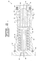
- pressure relief valve 32 is preferably a cartridge type valve that includes a plug body component 50 attached to a seat body component 51 to contain a valve member 52 and a biasing spring 53.
- a pneumatic, hydraulic, magnetic, or other spring type could be substituted as a biaser in place of spring 53.
- Biaser 53 normally biases valve member 52 toward a position that places valve surface 65 in contact with valve seat 69 to normally close relief valve inlet 36 to relief valve outlet 34.
- a washer 55 separates valve member 52 from biasing spring 53, which is positioned in a spring cavity 56 with a stop 62.
- Stop 62 defines the maximum travel of valve member 52, which includes a spring cavity vent passage 61, that vents spring cavity 56 to the low pressure at relief valve outlet 34.
- o-ring seals 60 and 64 as well as ring back up 63 isolate relief valve inlet 36 from relief valve outlet 34.
- the cartridge cavity 33 of pump body 15 includes internal threads that match external threads 57 on plug body component 50, allowing simple installation via appropriate torqueing via hex tool opening 58 about centerline 59.
- the valve opening pressure of pressure relief valve 32 can be finally tuned by adjusting the relative position of plug body component 50 relative to seat body component 51 before attaching the two via an annular weld at weld location 68. In other words, the pre-load from biaser 53 can be adjusted by telescoping plug body component 50 with respect to seat body component 51 until the force produces a predetermined valve opening pressure; the two components are then laser welded at weld location 68.
- pressure reduction valve 40 shares many features in common with pressure relief valve 32, but performs a much different function.
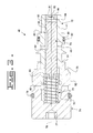
- pressure reduction valve 40 includes a plug body component 71 that telescopically receives a seat body component 72, within which are trapped a valve member 73 and a biaser, such as biasing spring 74.
- a washer 81 separates biaser 74 from valve member 73, which includes a control hydraulic surface 85 oriented in opposition to the force from spring 74.
- Biasing spring 74 is positioned in a spring chamber 76 that is vented to a low pressure space between o-ring seal 79 and external threads 92 via a spring chamber vent passage 80.
- valve member 73 acts as a spool valve member instead of as a poppet type valve member as in the embodiment of Figure 2.
- Pressure control chamber 88 is dampened from the effects of pressure fluctuations upstream of reduction valve pressure tap 42 by the inclusion of a restricted passage 87 defined in a plug 86 attached to seat body component 72.
- pressure reduction valve 40 is installed via a hex tool opening 77 with an appropriate torque about centerline 78 to seat seal surface 75 in an appropriate seat defined by the pump body in its cartridge cavity.
- valve member 73 moves to a position to open edge seat 84 so that inlet 43 is open to outlet 41 via fluid passage 82, which includes annulus 83.
- valve member 73 is pushed back toward a position to close edge seat 84.
- the valve opening pressure for pressure reduction valve 40 can be established by adjusting the relative position of plug body component 71 to seat body component 72 before they are attached at weld location 91.
- the present invention contemplates another valve operation parameter, namely the flow area through pressure reduction valve 40 when valve member 73 is in its open position, since the valve member 73 of pressure reduction valve 40 does not move between fixed stops.
- the present invention has been illustrated in the context of cartridge valves for a variable delivery pump, the present invention could find potential application in non-cartridge valve situations and/or in fluid handling apparatuses other than pumps. Nevertheless, the present invention finds particular application as a replaceable component in a fixed displacement variable delivery pump for use in supplying fluid to, and controlling pressure in, a common rail fuel injection system for an engine.
- the pressure relief valve 32 and the pressure reduction valve 40 could find potential application in a wide variety of different fluid systems, that may or may not benefit from a cartridge structure as shown in the illustrated embodiments.
- the valves of the present invention need not necessarily be cartridge valves, and could find potential application in fluid handling devices other than pumps.
- An assembly jig 100 includes an upper portion 101 that can be moved or fixed vertically with respect to a lower portion 102.
- a probe 104 can apply a force to control hydraulic surface 85, in a manner simulating fluid pressure if the valve were installed in pump 11.
- the force on valve member 73 can be measured by force indicator 105 in a known manner.
- Probe 104 and force indicator 105 are parts of upper portion 101, and maybe fixed in position on the upper portion by a probe clamp 106.
- the upper portion 101 also includes a seat component clamp 107 that may be maneuvered into a position to clamp seat body component 72 relative to upper portion 101.
- lower portion 102 includes a plug component clamp 120 for clamping onto plug body component 71 of pressure reduction valve 40.
- Assembly jig 100 also includes a source of pressurized fluid 13, such as pressurized air, connected to reduction valve inlet 41 via an inlet passage 112.
- Reduction valve inlet 43 is connected to a low pressure source via outlet passage 111, which includes a flow meter 110 that can measure the flow rate of fluid through outlet passage 111, and hence through pressure reduction valve 40.
- source 113 preferably produces a predetermined pressure gradient across pressure reduction valve 40 so that a predetermined flow rate of a known gas at a predetermined pressure gradient can be calibrated to indicate a predetermined flow area through pressure reduction valve 40. This predetermined flow area would be indicative of the flow area through the valve when in its open position.
- the pressure gradient through or across pressure reduction valve 40 when in assembly jig 100 is in the reverse to that normally experienced when the valve is installed in the pump Figure 1.
- Assembly proceeds by placing the components that make up pressure reduction valve 40 in the gravity held manner shown in Figure 4 within assembly jig 100.
- plug component 71 is clamped to plug component clamp 120 of lower portion 102, while upper portion 101 clamps to seat body component 72 via seat component clamp 107.
- probe 104 is moved into a position adjacent to valve member 73.
- the flow area through the valve is adjusted by adjusting the position of valve member 73 relative to seat body component 72 with probe 104 until edge seat 84 is closed. This closed point is generally indicated when the pressurized fluid leakage past edge seat 84 is below some predetermined level. At this point, flow meter 110 is recalibrated to zero.
- valve member 73 moves toward a position opening flow past edge seat 84.
- flow meter 110 indicates some predetermined flow rate, the operator should know that it is indicative of a predetermined flow area past edge seat 84.
- this predetermined flow area is preferably similar to the maximum flow area through the pump output controller 18, so that the pressure reduction valve operation corresponds closely to the flow area fluctuations through the electro hydraulic actuator 27 of the pump controller 18.
- probe clamp 106 is activated to fix the position of valve member 73 with respect to seat body component 72 as shown in Figure 7.
- the upper portion 101 is moved vertically with respect to the lower portion 102 until force indicator 105 indicates a predetermined load on valve member 73 when it is in its open position as defined by the steps of Figures 6 and 7.
- This movement causes seat body component 72 to telescope within plug body component 71.
- the two body components are laser welded at weld location 91, such as by rotating assembly jig 100, while appropriately positioning laser welder 130.
- the now assembled pressure reduction valve 40 will be biased toward a closed position but will open when a fluid pressure force in a control hydraulic surface 85 of valve member 73 drops below a predetermined level.
- the pressure relief valve 32 is assembled much in a similar manner to that of pressure reduction valve 40, except that no fluid flow rate measurements need be done.
- the unattached valve is positioned in the assembly jig 100.
- the respective seat and body component clamps are then clamped onto the respective seat and body components of the valve.
- the probe is moved in position into contact with the valve member. Nevertheless, the fluid flow apparatus can still be used as a method of determining when the valve opened in the case of assembling the pressure relief valve 32.
- the respective body and seat components are telescoped with respect to one another until the probe indicates that the force indicator 105 of probe 104 indicates the desired valve opening pressure.
- the two body components are then laser welded in a manner similar to that described with respect to the pressure reduction valve 40 assembly.
- this valve operating parameter has been illustrated as a valve opening pressure for a pressure reduction valve along with a predetermined valve flow area when such a valve is in its open position, as well as a predetermined valve opening pressure for a pressure relief valve.
- the present invention allows for the possible elimination of category parts, such as spacers in order to trim a valve produced to some desired valve opening pressure.
Landscapes
- Engineering & Computer Science (AREA)
- General Engineering & Computer Science (AREA)
- Mechanical Engineering (AREA)
- Safety Valves (AREA)
- Automatic Assembly (AREA)
Abstract
Description
- The present invention relates generally to valves, and more particularly to valves with a preset operation parameter.
- In one class of valves, the valve member is intended to move to a particular position when acted upon by a predetermined force. For instance, in the case of a pressure relief valve, the valve member would be biased toward a closed position, but could open when fluid pressure acting on an opening hydraulic surface exceeds some predetermined valve opening pressure. In another example, a pressure reducing valve moves to an open position when pressure on the low pressure side of the valve drops below some predetermined valve opening pressure. Because these valves must often be comprised of several components, and each of those components must have a realistic manufacturing tolerance, mass producing valves with consistent valve opening pressures can be problematic. Some of these problems can be attributed to difficulty in setting a desired valve operation parameter, such as valve opening pressure, when stacked geometrical or other tolerances result in a plurality of valves all with slightly differently shaped or strengthened components. Variations on the desired valve operation parameter can often be a strong function of variability among component tolerances, and the problem is often compounded by stacked tolerances from multiple components.
- The present invention is directed to these and other problems associated with mass producing valves with consistent and/or predictable valve operating parameters.
- In one aspect, a valve assembly includes a first body component fixed with respect to a second body component in a selected relative position, which corresponds to a predetermined valve operation parameter, such as a valve opening pressure.
- In another aspect, a method of assembling a valve includes a step of adjusting a relative positioning of a first body component relative to a second body component until reaching a relative position that corresponds to a predetermined valve operation parameter. The first body component and the second body component are then fixed in the relative position.
- In still another aspect, a pump includes at least one cartridge valve assembly threadably attached to a pump body. Each of the cartridge valves has a first body component fixed with respect to a second body component in a selected relative position that corresponds to a predetermined valve operation parameter.
-
- Figure 1 is a schematic illustration of a pump according to one aspect of the present invention;
- Figure 2 is a sectioned side diagrammatic view of a pressure relief valve according to another aspect of the present invention;
- Figure 3 is a sectioned side diagrammatic view of a pressure reducing valve according to still another aspect of the present invention; and
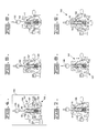
- Figures 4-9 show the assembly process for a valve of the type shown in Figure 3.
-
- Referring now to Figure 1, a
pump system 10 includes an electronically controlledpump 11, which is controlled in a conventional manner by anelectronic control module 12. For instance,pump 11 could be a known fixed displacement, variably output axial piston pump of a type generally described in co-owned U.S. Patent 6,035,828 to Anderson et al. For example, that pump might include a plurality of pistons driven to reciprocate by a rotating angled swash plate. An output controller would control whether the fluid displaced by the pump pistons is pushed into a high pressure outlet or merely returned to a low pressure side for recirculation. The output controller could be of any suitable structure and be controlled by anelectronic control module 12 in a conventional manner. - Pump 11 includes a low pressure inlet connected to a low
pressure inlet gallery 20, and ahigh pressure outlet 16 connected to a highpressure outlet gallery 30. Lowpressure inlet gallery 20 andhigh pressure gallery 30 are potentially connectable viapumping portion 24, acontroller leak passage 29 or apressure relief passage 31. In one aspect of the invention,pump body 15 includes acartridge cavity 33 holding a pressure relief valve to normally closepressure relief passage 31. In another aspect, apressure reduction valve 40 is positioned in acartridge cavity 47 so thatpump output controller 18 is provided with a relatively medium pressure, which is stepped down from the highpressure output gallery 30. When in operation, a rotatingshaft 17 causes apump portion 24 to draw fluid from lowpressure inlet gallery 20 viainternal supply passage 22, and deliver the same to a fluid diverting means 19. Depending upon the state of fluid diverting means 19, a usually large portion of the fluid is pushed into highpressure outlet gallery 30 viahigh pressure passage 26, and a typically lessor portion is diverted intolow pressure passage 25 for recirculation to lowpressure inlet gallery 20. Fluid diverting means 19 is a portion ofpump output controller 18, which also includes an electrohydraulic actuator 27 in communication withelectronic control module 12 via acommunication line 28. - The output rate of
pump 11 is generally determined by the rotation rate ofshaft 17 and the ratio of fluid delivered to respectivehigh pressure passage 26 and lowpressure return passage 25 by fluid diverting means 19, as determined by electrohydraulic actuator 27. For example, fluid diverting means 19 could represent a set of sleeves mounted around pump pistons. The sleeves can be moved by an electrohydraulic actuator 27 between positions that port different fractions of the pumping piston's stroke fluid back to the lowpressure inlet gallery 20. The sleeves can also be positioned such that virtually all of the fluid displaced by the pump pistons is pushed intohigh pressure passage 26. In one example, the electrohydraulic actuator 27 consumes some relatively small amount of high pressure fluid fromoutlet gallery 30 to perform its function of adjusting the state of fluid diverting means 19. However, the amount of fluid used for this purpose is reduced, and the pressure at which theoutput controller 18 operates is made relatively uniform by the inclusion ofpressure reduction valve 40. Thepressure reduction valve 40 is intended to provide electrohydraulic actuator 27 with a steady supply of uniform pressure fluid via areduction valve inlet 43 and areduction valve outlet 41. The state ofpressure reduction valve 40 is preferably determined via a reductionvalve pressure tap 42, which communicates the operating pressure of the electrohydraulic actuator 27 topressure reduction valve 40. When pressure in electrohydraulic actuator 27 drops below a pre-determined threshold,pressure reduction valve 43 opensinlet 43 larger tooutlet 41 to raise pressure inactuator 27. When pressure exceeds a predetermined maximum pressure,pressure reduction valve 43 can move toward a closed position. When pressure inoutlet gallery 30 exceeds a predetermined maximum,pressure relief valve 32 relieves pressure toinlet gallery 20 viapressure relief passage 31. In particular, when pressure in the upstream portion ofrelief passage 31 exceeds a predetermined pressure,relief valve inlet 36 is opened torelief valve outlet 34 to vent excess pressure. - Referring now to Figure 2,
pressure relief valve 32 is preferably a cartridge type valve that includes aplug body component 50 attached to aseat body component 51 to contain avalve member 52 and abiasing spring 53. A pneumatic, hydraulic, magnetic, or other spring type could be substituted as a biaser in place ofspring 53. Biaser 53 normally biasesvalve member 52 toward a position that placesvalve surface 65 in contact withvalve seat 69 to normally closerelief valve inlet 36 torelief valve outlet 34. Awasher 55 separatesvalve member 52 from biasingspring 53, which is positioned in aspring cavity 56 with astop 62. When fluid pressure acting on an openinghydraulic surface 66 exceeds a predetermined valve opening pressure.Valve surface 65 separates fromvalve seat 69 toopen fluid passage 67.Stop 62 defines the maximum travel ofvalve member 52, which includes a springcavity vent passage 61, thatvents spring cavity 56 to the low pressure atrelief valve outlet 34. When installed inpump body 15, o-ring seals relief valve inlet 36 fromrelief valve outlet 34. Thecartridge cavity 33 ofpump body 15 includes internal threads that matchexternal threads 57 onplug body component 50, allowing simple installation via appropriate torqueing via hex tool opening 58 aboutcenterline 59. The valve opening pressure ofpressure relief valve 32 can be finally tuned by adjusting the relative position ofplug body component 50 relative toseat body component 51 before attaching the two via an annular weld atweld location 68. In other words, the pre-load frombiaser 53 can be adjusted by telescopingplug body component 50 with respect toseat body component 51 until the force produces a predetermined valve opening pressure; the two components are then laser welded atweld location 68. - Referring now to Figure 3,
pressure reduction valve 40 shares many features in common withpressure relief valve 32, but performs a much different function. Likepressure relief valve 32,pressure reduction valve 40 includes aplug body component 71 that telescopically receives aseat body component 72, within which are trapped avalve member 73 and a biaser, such as biasingspring 74. Awasher 81 separatesbiaser 74 fromvalve member 73, which includes a controlhydraulic surface 85 oriented in opposition to the force fromspring 74.Biasing spring 74 is positioned in aspring chamber 76 that is vented to a low pressure space between o-ring seal 79 andexternal threads 92 via a springchamber vent passage 80. Depending upon the fluid pressure inpressure control chamber 88 acting on controlhydraulic surface 85, and the force from biasingspring 74,reduction valve inlet 43 can be opened to reduction ofoutlet 41 past edge seat 84. Thus, in this example embodiment,valve member 73 acts as a spool valve member instead of as a poppet type valve member as in the embodiment of Figure 2.Pressure control chamber 88 is dampened from the effects of pressure fluctuations upstream of reductionvalve pressure tap 42 by the inclusion of a restrictedpassage 87 defined in aplug 86 attached toseat body component 72. When installed inpump body 15, aseal surface 75 and o-ring seal 90 and ring back up 89 isolate the higher pressure existing atreduction valve inlet 43 from the medium pressure existing atreduction valve outlet 41 andpressure control chamber 88. Like thepressure relief valve 32,pressure reduction valve 40 is installed via a hex tool opening 77 with an appropriate torque aboutcenterline 78 to seatseal surface 75 in an appropriate seat defined by the pump body in its cartridge cavity. When pressure in thepressure control chamber 88 drops below a predetermined value,valve member 73 moves to a position to open edge seat 84 so thatinlet 43 is open tooutlet 41 viafluid passage 82, which includesannulus 83. When pressure is higher inpressure control chamber 88,valve member 73 is pushed back toward a position to close edge seat 84. Like thepressure relief valve 32, the valve opening pressure forpressure reduction valve 40 can be established by adjusting the relative position ofplug body component 71 toseat body component 72 before they are attached atweld location 91. In addition, the present invention contemplates another valve operation parameter, namely the flow area throughpressure reduction valve 40 whenvalve member 73 is in its open position, since thevalve member 73 ofpressure reduction valve 40 does not move between fixed stops. - Although the present invention has been illustrated in the context of cartridge valves for a variable delivery pump, the present invention could find potential application in non-cartridge valve situations and/or in fluid handling apparatuses other than pumps. Nevertheless, the present invention finds particular application as a replaceable component in a fixed displacement variable delivery pump for use in supplying fluid to, and controlling pressure in, a common rail fuel injection system for an engine. For instance, those skilled in the art will appreciate that both the
pressure relief valve 32 and thepressure reduction valve 40 could find potential application in a wide variety of different fluid systems, that may or may not benefit from a cartridge structure as shown in the illustrated embodiments. In other words, the valves of the present invention need not necessarily be cartridge valves, and could find potential application in fluid handling devices other than pumps. - Referring now to Figures 4-9, the assembly procedure for a pressure reduction valve is illustrated to show how a valve according to the present invention can be assembled to produce a predetermined valve operation parameter, such as valve opening pressure, even in the light of geometrical variations in different parts as well as variations in spring strength. An
assembly jig 100 includes anupper portion 101 that can be moved or fixed vertically with respect to alower portion 102. Whenassembly jig 100 is in operation, aprobe 104 can apply a force to controlhydraulic surface 85, in a manner simulating fluid pressure if the valve were installed inpump 11. The force onvalve member 73 can be measured byforce indicator 105 in a known manner.Probe 104 andforce indicator 105 are parts ofupper portion 101, and maybe fixed in position on the upper portion by aprobe clamp 106. Theupper portion 101 also includes aseat component clamp 107 that may be maneuvered into a position to clampseat body component 72 relative toupper portion 101. Likewise,lower portion 102 includes aplug component clamp 120 for clamping ontoplug body component 71 ofpressure reduction valve 40.Assembly jig 100 also includes a source of pressurized fluid 13, such as pressurized air, connected toreduction valve inlet 41 via an inlet passage 112.Reduction valve inlet 43 is connected to a low pressure source via outlet passage 111, which includes aflow meter 110 that can measure the flow rate of fluid through outlet passage 111, and hence throughpressure reduction valve 40. Those skilled in the art will appreciate thatsource 113 preferably produces a predetermined pressure gradient acrosspressure reduction valve 40 so that a predetermined flow rate of a known gas at a predetermined pressure gradient can be calibrated to indicate a predetermined flow area throughpressure reduction valve 40. This predetermined flow area would be indicative of the flow area through the valve when in its open position. Those skilled in the art will also appreciate that the pressure gradient through or acrosspressure reduction valve 40 when inassembly jig 100 is in the reverse to that normally experienced when the valve is installed in the pump Figure 1. - Assembly proceeds by placing the components that make up
pressure reduction valve 40 in the gravity held manner shown in Figure 4 withinassembly jig 100. Next, as shown in Figure 5,plug component 71 is clamped to plugcomponent clamp 120 oflower portion 102, whileupper portion 101 clamps to seatbody component 72 viaseat component clamp 107. In addition,probe 104 is moved into a position adjacent tovalve member 73. In the next step, shown in Figure 6, the flow area through the valve is adjusted by adjusting the position ofvalve member 73 relative to seatbody component 72 withprobe 104 until edge seat 84 is closed. This closed point is generally indicated when the pressurized fluid leakage past edge seat 84 is below some predetermined level. At this point, flowmeter 110 is recalibrated to zero. Next, the force produced byprobe 104 is reduced so thatvalve member 73 moves toward a position opening flow past edge seat 84. Whenflow meter 110 indicates some predetermined flow rate, the operator should know that it is indicative of a predetermined flow area past edge seat 84. In the illustrated embodiment, this predetermined flow area is preferably similar to the maximum flow area through thepump output controller 18, so that the pressure reduction valve operation corresponds closely to the flow area fluctuations through the electrohydraulic actuator 27 of thepump controller 18. Thus, when a predetermined flow area through the valve is achieved,probe clamp 106 is activated to fix the position ofvalve member 73 with respect toseat body component 72 as shown in Figure 7. In the step shown in Figure 8, theupper portion 101 is moved vertically with respect to thelower portion 102 untilforce indicator 105 indicates a predetermined load onvalve member 73 when it is in its open position as defined by the steps of Figures 6 and 7. This movement causesseat body component 72 to telescope withinplug body component 71. Thus, when the desired opening area and opening pressure force are achieved as shown in Figures 6, 7 and 8, the two body components are laser welded atweld location 91, such as by rotatingassembly jig 100, while appropriately positioninglaser welder 130. Those skilled in the art will appreciate that the now assembledpressure reduction valve 40 will be biased toward a closed position but will open when a fluid pressure force in a controlhydraulic surface 85 ofvalve member 73 drops below a predetermined level. - The
pressure relief valve 32 is assembled much in a similar manner to that ofpressure reduction valve 40, except that no fluid flow rate measurements need be done. In other words, the unattached valve is positioned in theassembly jig 100. The respective seat and body component clamps are then clamped onto the respective seat and body components of the valve. Next, the probe is moved in position into contact with the valve member. Nevertheless, the fluid flow apparatus can still be used as a method of determining when the valve opened in the case of assembling thepressure relief valve 32. The respective body and seat components are telescoped with respect to one another until the probe indicates that theforce indicator 105 ofprobe 104 indicates the desired valve opening pressure. The two body components are then laser welded in a manner similar to that described with respect to thepressure reduction valve 40 assembly. - Those skilled in the art will appreciate that the structure and assembly strategy of the present invention allows tolerances for valve components to be relaxed while at the same time having the ability to tighten the tolerances on an important valve feature, such as a valve operation parameter. In the illustrated embodiments, this valve operating parameter has been illustrated as a valve opening pressure for a pressure reduction valve along with a predetermined valve flow area when such a valve is in its open position, as well as a predetermined valve opening pressure for a pressure relief valve. Thus, the present invention allows for the possible elimination of category parts, such as spacers in order to trim a valve produced to some desired valve opening pressure. By making the valve in a cartridge form and laser welding it, a tamper resistant package is produced that is an easily serviceable aspect of the pump illustrated in Figure 1. Thus, the present invention provides a structure and methodology capable of reducing costs while simultaneously improving quality, reliability, and predictability.
- It should be understood that the above description is intended for illustrative purposes only, and is not intended to limit the scope of the present invention in any way. For instance, while the invention has been illustrated in the context of hydraulic valves, the present invention is also applicable to pneumatic systems. In addition, while the invention has been illustrated in the context of a valve opening pressure, the invention is also applicable to setting a valve member movement force. That force could be supplied by fluid pressure or an electrical actuator. In addition, valve movement may be a closing force in another application, rather than valve opening forces as in the illustrated embodiments. Thus, those skilled in the art will appreciate that other aspects, objects, and advantages of the invention can be obtained from a study of the drawings, the disclosure and the appended claims.
Claims (10)
- A valve assembly (32,40) comprising:a valve body including a first body component (50,71) being fixed with respect to a second body component (51,72) in a selected relative position; andsaid selected relative position corresponding to a predetermined valve operation parameter.
- The valve assembly (32,40) of claim 1 wherein said predetermined valve operation parameter includes a valve opening force.
- The valve assembly of claim 2 including a valve member (52,73) movably positioned in said valve body (50,51,71,72);
said valve body (50,51,71,72) defines an inlet (36,43) and an outlet (34,41); and
said valve member (52,73) moving to a position that opens said inlet (36,43) to said outlet (34,41) when a control force on said valve member (52,73) is one of greater than said valve opening force and less than said valve opening force. - The valve assembly (32,40) of claim 1 including:a valve member (52,73) at least partially positioned in said valve body (50,51,71,72), and being movable between a first position and a second position; anda biaser (53,74) operably coupled to bias said valve member toward said first position.
- The valve assembly (32,40) of claim 4 wherein said valve member (52,73) including a control surface (66,85) oriented in opposition to a force from said biaser (53,74) and wherein said biaser including a spring (53,74).
- The valve assembly (32,40) of claim 1 including a pair of annular sealing members (60,64,79,90) mounted on an outside surface of said valve body (50,51,71,72), and said valve body (50,51,71,72) defining at least one fluid passage (67,82) located in an area between said annular sealing members (60,64,79,90).
- The valve assembly (32,40) of claim 6 wherein said valve body (50,51,71,72) including a set of external threads (57,92).
- The valve assembly of claim 6 wherein said at least one fluid passage (67,82) including one of an inlet (36,43) and an outlet (34,41);
an other of said inlet (36,43) and said outlet (34,41) opening through said valve body (50,51,71,72) at a location outside said area. - A method of assembling a valve (32,40), comprising the steps of:adjusting a relative positioning of a first body component (50,71) relative to a second body component (51,72) until reaching a relative position that corresponds to a predetermined valve operation parameter; andfixing the first body component (50,71) to the second body component (51,72) in the relative position.
- The method of claim 10 wherein the adjusting step including:setting a predetermined valve opening pressure;moving the first body component (50,71) relative to the second body component (51,72) along a line (59,78);telescoping the first body component (50,71) with respect to the second body component (51,72);measuring a flow rate through the valve (40) for a predetermined fluid at a predetermined pressure gradient;measuring a biasing force on a valve member (52,72) when said first body component (50,71) and said second body component (51,72) are at a plurality of relative positions; andwelding the first body component (50,71) to the second body component (51,72).
Applications Claiming Priority (2)
| Application Number | Priority Date | Filing Date | Title |
|---|---|---|---|
| US191913 | 2002-07-09 | ||
| US10/191,913 US7125230B2 (en) | 2002-07-09 | 2002-07-09 | Valve with operation parameter set at assembly and pump using same |
Publications (3)
| Publication Number | Publication Date |
|---|---|
| EP1380780A2 true EP1380780A2 (en) | 2004-01-14 |
| EP1380780A3 EP1380780A3 (en) | 2004-02-04 |
| EP1380780B1 EP1380780B1 (en) | 2006-09-13 |
Family
ID=29735298
Family Applications (1)
| Application Number | Title | Priority Date | Filing Date |
|---|---|---|---|
| EP20030011802 Expired - Lifetime EP1380780B1 (en) | 2002-07-09 | 2003-05-26 | Valve with operation parameter set at assembly and pump using same |
Country Status (3)
| Country | Link |
|---|---|
| US (1) | US7125230B2 (en) |
| EP (1) | EP1380780B1 (en) |
| DE (1) | DE60308275T2 (en) |
Cited By (3)
| Publication number | Priority date | Publication date | Assignee | Title |
|---|---|---|---|---|
| EP2282089A1 (en) | 2009-08-05 | 2011-02-09 | HAWE Hydraulik SE | Hydraulic valve |
| DE102007047902B4 (en) * | 2006-12-20 | 2011-08-25 | DENSO CORPORATION, Aichi-pref. | piston valve |
| US20160061340A1 (en) * | 2014-08-28 | 2016-03-03 | Apex Medical Corp. | Pneumatic valve and air mattress assembly having pneumatic valve |
Families Citing this family (5)
| Publication number | Priority date | Publication date | Assignee | Title |
|---|---|---|---|---|
| JP2005248847A (en) * | 2004-03-04 | 2005-09-15 | Bosch Automotive Systems Corp | Sealing structure for fuel passage and fuel injection valve equipped with the sealing structure |
| JP5424213B2 (en) * | 2007-07-18 | 2014-02-26 | シェフラー テクノロジーズ アクチエンゲゼルシャフト ウント コンパニー コマンディートゲゼルシャフト | Pressure relief valve for hydraulic equipment |
| ITBO20110600A1 (en) * | 2011-10-21 | 2013-04-22 | S T S R L | APPARATUS AND METHOD OF CALIBRATION OF A VALVE |
| US10562165B2 (en) * | 2016-04-10 | 2020-02-18 | Caterpillar Inc. | Hydraulic hammer |
| CN109882402A (en) * | 2019-03-11 | 2019-06-14 | 安徽理工大学 | A kind of flame proof safety device of water pump for mining |
Citations (1)
| Publication number | Priority date | Publication date | Assignee | Title |
|---|---|---|---|---|
| US6035828A (en) | 1998-03-11 | 2000-03-14 | Caterpillar Inc. | Hydraulically-actuated system having a variable delivery fixed displacement pump |
Family Cites Families (33)
| Publication number | Priority date | Publication date | Assignee | Title |
|---|---|---|---|---|
| US2393544A (en) | 1943-08-05 | 1946-01-22 | Bendix Aviat Corp | Fuel injection pump |
| US3650294A (en) * | 1969-10-20 | 1972-03-21 | Kichiro Satoh | Pressure retaining valve |
| US3886969A (en) * | 1973-05-23 | 1975-06-03 | Us Energy | Time delay vent valve |
| US3943968A (en) * | 1975-01-06 | 1976-03-16 | Parker-Hannifin Corporation | Combination lock and relief valve for hydraulic systems |
| GB1524436A (en) | 1975-07-21 | 1978-09-13 | Johnson L E | Fuel injection valves and their manufacture |
| US4116417A (en) * | 1975-09-08 | 1978-09-26 | Ward Orin Larsen | Needle valve type pump injector |
| AU6540680A (en) | 1979-12-14 | 1981-06-18 | Kaye, R.S. | Fuel regulator |
| US4494570A (en) * | 1983-03-04 | 1985-01-22 | Adkins Charles H | LP Gas safety valve |
| US4541391A (en) | 1984-03-27 | 1985-09-17 | Caterpillar Tractor Co. | Timing control for fuel injection apparatus |
| US4531492A (en) | 1984-03-27 | 1985-07-30 | Caterpillar Tractor Co. | Fuel injection timing and governor control apparatus |
| US4531494A (en) | 1984-03-27 | 1985-07-30 | Caterpillar Tractor Co. | Distributor fuel injection pump having a nutator pump subassembly |
| CH662629A5 (en) * | 1984-12-28 | 1987-10-15 | Paul Comment | PRESSURE REDUCER-REGULATOR FOR THE DISTRIBUTION OF A GASEOUS, LIQUID, VISCOUS, POWDERY OR PASTY PRODUCT. |
| US4671063A (en) * | 1985-05-29 | 1987-06-09 | Midwestern Reliable Equipment, Inc. | Hydraulic intensifier |
| US4718442A (en) | 1986-02-27 | 1988-01-12 | Helix Technology Corporation | Cryogenic refrigerator compressor with externally adjustable by-pass/relief valve |
| IL93504A (en) * | 1990-02-23 | 1994-01-25 | Rosenberg Peretz | Quick-action shut-off valve |
| CH683803A5 (en) * | 1990-05-18 | 1994-05-13 | Hobac S A | automatic control valve. |
| US5515829A (en) | 1994-05-20 | 1996-05-14 | Caterpillar Inc. | Variable-displacement actuating fluid pump for a HEUI fuel system |
| GB9416783D0 (en) | 1994-08-19 | 1994-10-12 | Microhydraulics Inc | Variable delivery pump with spill control |
| US6116273A (en) * | 1994-12-06 | 2000-09-12 | Cummins Engine Company, Inc. | Fuel metering check valve arrangement for a time-pressure controlled unit fuel injector |
| US5727594A (en) * | 1995-02-09 | 1998-03-17 | Choksi; Pradip | Low actuation pressure unidirectional flow valve |
| US5707210A (en) * | 1995-10-13 | 1998-01-13 | Copeland Corporation | Scroll machine with overheating protection |
| EP1048849B1 (en) | 1996-06-07 | 2005-03-16 | Hydro Leduc | High pressure liquid pump |
| DE69906740T2 (en) * | 1998-07-09 | 2004-01-29 | Parker Hannifin Corp | CHECK VALVE |
| US6494688B1 (en) * | 1999-07-15 | 2002-12-17 | Scroll Technologies | Force-fit scroll compressor components |
| DE19961923A1 (en) * | 1999-12-22 | 2001-07-05 | Bosch Gmbh Robert | Fuel delivery module for vehicle has jet pump that pumps fuel from fuel tank to storage container next to feed assembly, connected to flow channel by channel on storage container floor |
| US6655925B1 (en) * | 2000-03-08 | 2003-12-02 | Devilbiss Air Power Company | Air compressor manifold assembly |
| US6742995B1 (en) * | 2000-03-08 | 2004-06-01 | Devilbiss Air Power Company | Air compressor assembly |
| ATE333616T1 (en) * | 2000-05-23 | 2006-08-15 | Boc Group Plc | LOADING VALVE FOR GAS |
| US6447257B2 (en) * | 2000-07-19 | 2002-09-10 | Campbell Hausfeld/Scott Fetzer Company | Air compressor assembly with vibration damping structure |
| US6374852B1 (en) * | 2000-08-09 | 2002-04-23 | Brightvalve, Llc | Leak arresting valve |
| US6679683B2 (en) * | 2000-10-16 | 2004-01-20 | Copeland Corporation | Dual volume-ratio scroll machine |
| DE10139499C1 (en) * | 2001-08-10 | 2003-03-13 | Lucas Automotive Gmbh | Composite component, in particular valve, and method for producing the same |
| US6877525B2 (en) * | 2001-11-07 | 2005-04-12 | Delphi Technologies, Inc. | Check valve for fuel pump |
-
2002
- 2002-07-09 US US10/191,913 patent/US7125230B2/en not_active Expired - Lifetime
-
2003
- 2003-05-26 EP EP20030011802 patent/EP1380780B1/en not_active Expired - Lifetime
- 2003-05-26 DE DE2003608275 patent/DE60308275T2/en not_active Expired - Lifetime
Patent Citations (1)
| Publication number | Priority date | Publication date | Assignee | Title |
|---|---|---|---|---|
| US6035828A (en) | 1998-03-11 | 2000-03-14 | Caterpillar Inc. | Hydraulically-actuated system having a variable delivery fixed displacement pump |
Cited By (3)
| Publication number | Priority date | Publication date | Assignee | Title |
|---|---|---|---|---|
| DE102007047902B4 (en) * | 2006-12-20 | 2011-08-25 | DENSO CORPORATION, Aichi-pref. | piston valve |
| EP2282089A1 (en) | 2009-08-05 | 2011-02-09 | HAWE Hydraulik SE | Hydraulic valve |
| US20160061340A1 (en) * | 2014-08-28 | 2016-03-03 | Apex Medical Corp. | Pneumatic valve and air mattress assembly having pneumatic valve |
Also Published As
| Publication number | Publication date |
|---|---|
| EP1380780B1 (en) | 2006-09-13 |
| US7125230B2 (en) | 2006-10-24 |
| US20040009080A1 (en) | 2004-01-15 |
| EP1380780A3 (en) | 2004-02-04 |
| DE60308275D1 (en) | 2006-10-26 |
| DE60308275T2 (en) | 2007-09-20 |
Similar Documents
| Publication | Publication Date | Title |
|---|---|---|
| CA2756846C (en) | Flow sensing shutoff valve | |
| EP1269003B1 (en) | A fluid seal apparatus and method for dynamically controlling sealing-fluid pressure | |
| AU689741B2 (en) | Leak tester and leak testing method | |
| EP1425529B1 (en) | Pressure regulating valve with adjustment features | |
| JP2683214B2 (en) | Three-way valve assembly | |
| EP1835169B1 (en) | High-pressure fuel pump | |
| US11421600B1 (en) | Fuel supply system with combined metering and shutoff valve | |
| JPS63147966A (en) | Fuel injector | |
| ITTO991054A1 (en) | VALVE SYSTEM FOR INLET PRESSURE CONTROL OF A LIQUID IN A HIGH PRESSURE PUMP, AND RELATED OVERPRESSURE VALVE | |
| JPH02501337A (en) | Improved modulating hydraulic pressure control valve and its assembly method | |
| US20050242310A1 (en) | Control valve apparatus and pressure circuit | |
| JP4791798B2 (en) | Fuel injection device | |
| DE112010001987T5 (en) | Piezoelectric direct acting fuel injector with hydraulic connection | |
| US7125230B2 (en) | Valve with operation parameter set at assembly and pump using same | |
| JPH04504157A (en) | Variable compression ratio internal combustion engine | |
| CA2020924C (en) | Logic valve | |
| US4869219A (en) | Dual spring air fuel control for the PT fuel system | |
| JP4273474B2 (en) | Initial adjustment of damping force adjusting mechanism, inspection method and damping force test device | |
| US20050263117A1 (en) | Device and a method for the generation of pressure pulses | |
| US5092299A (en) | Air fuel control for a PT fuel system | |
| US8151746B2 (en) | Control system for a variable compression engine | |
| JPH05149210A (en) | Fuel injection valve of internal combustion engine | |
| US6526943B2 (en) | Control valve for hydraulically oil activated fuel injector | |
| DE102023116280A1 (en) | Injector for directly injecting a gas into the combustion chamber of a reciprocating piston internal combustion engine and method for operating a reciprocating piston internal combustion engine | |
| US9732715B2 (en) | Two stage valve with conical seat for flow shut-off and spool knife edge for metering flow control |
Legal Events
| Date | Code | Title | Description |
|---|---|---|---|
| PUAI | Public reference made under article 153(3) epc to a published international application that has entered the european phase |
Free format text: ORIGINAL CODE: 0009012 |
|
| PUAL | Search report despatched |
Free format text: ORIGINAL CODE: 0009013 |
|
| AK | Designated contracting states |
Kind code of ref document: A2 Designated state(s): AT BE BG CH CY CZ DE DK EE ES FI FR GB GR HU IE IT LI LU MC NL PT RO SE SI SK TR |
|
| AX | Request for extension of the european patent |
Extension state: AL LT LV MK |
|
| AK | Designated contracting states |
Kind code of ref document: A3 Designated state(s): AT BE BG CH CY CZ DE DK EE ES FI FR GB GR HU IE IT LI LU MC NL PT RO SE SI SK TR |
|
| AX | Request for extension of the european patent |
Extension state: AL LT LV MK |
|
| 17P | Request for examination filed |
Effective date: 20040803 |
|
| AKX | Designation fees paid |
Designated state(s): DE GB |
|
| 17Q | First examination report despatched |
Effective date: 20041012 |
|
| GRAP | Despatch of communication of intention to grant a patent |
Free format text: ORIGINAL CODE: EPIDOSNIGR1 |
|
| GRAS | Grant fee paid |
Free format text: ORIGINAL CODE: EPIDOSNIGR3 |
|
| GRAA | (expected) grant |
Free format text: ORIGINAL CODE: 0009210 |
|
| AK | Designated contracting states |
Kind code of ref document: B1 Designated state(s): DE GB |
|
| REG | Reference to a national code |
Ref country code: GB Ref legal event code: FG4D |
|
| REF | Corresponds to: |
Ref document number: 60308275 Country of ref document: DE Date of ref document: 20061026 Kind code of ref document: P |
|
| PLBE | No opposition filed within time limit |
Free format text: ORIGINAL CODE: 0009261 |
|
| STAA | Information on the status of an ep patent application or granted ep patent |
Free format text: STATUS: NO OPPOSITION FILED WITHIN TIME LIMIT |
|
| 26N | No opposition filed |
Effective date: 20070614 |
|
| PGFP | Annual fee paid to national office [announced via postgrant information from national office to epo] |
Ref country code: GB Payment date: 20160426 Year of fee payment: 14 Ref country code: DE Payment date: 20160524 Year of fee payment: 14 |
|
| REG | Reference to a national code |
Ref country code: DE Ref legal event code: R119 Ref document number: 60308275 Country of ref document: DE |
|
| GBPC | Gb: european patent ceased through non-payment of renewal fee |
Effective date: 20170526 |
|
| PG25 | Lapsed in a contracting state [announced via postgrant information from national office to epo] |
Ref country code: DE Free format text: LAPSE BECAUSE OF NON-PAYMENT OF DUE FEES Effective date: 20171201 Ref country code: GB Free format text: LAPSE BECAUSE OF NON-PAYMENT OF DUE FEES Effective date: 20170526 |