EP1380769A2 - Toroidal-type continuously variable transmission and method for producing torque transmitting member thereof - Google Patents
Toroidal-type continuously variable transmission and method for producing torque transmitting member thereof Download PDFInfo
- Publication number
- EP1380769A2 EP1380769A2 EP03015819A EP03015819A EP1380769A2 EP 1380769 A2 EP1380769 A2 EP 1380769A2 EP 03015819 A EP03015819 A EP 03015819A EP 03015819 A EP03015819 A EP 03015819A EP 1380769 A2 EP1380769 A2 EP 1380769A2
- Authority
- EP
- European Patent Office
- Prior art keywords
- contact portion
- range
- roller
- toroidal
- bearing steel
- Prior art date
- Legal status (The legal status is an assumption and is not a legal conclusion. Google has not performed a legal analysis and makes no representation as to the accuracy of the status listed.)
- Granted
Links
Images


Classifications
-
- F—MECHANICAL ENGINEERING; LIGHTING; HEATING; WEAPONS; BLASTING
- F16—ENGINEERING ELEMENTS AND UNITS; GENERAL MEASURES FOR PRODUCING AND MAINTAINING EFFECTIVE FUNCTIONING OF MACHINES OR INSTALLATIONS; THERMAL INSULATION IN GENERAL
- F16H—GEARING
- F16H55/00—Elements with teeth or friction surfaces for conveying motion; Worms, pulleys or sheaves for gearing mechanisms
- F16H55/32—Friction members
-
- H—ELECTRICITY
- H04—ELECTRIC COMMUNICATION TECHNIQUE
- H04W—WIRELESS COMMUNICATION NETWORKS
- H04W4/00—Services specially adapted for wireless communication networks; Facilities therefor
- H04W4/02—Services making use of location information
-
- C—CHEMISTRY; METALLURGY
- C22—METALLURGY; FERROUS OR NON-FERROUS ALLOYS; TREATMENT OF ALLOYS OR NON-FERROUS METALS
- C22C—ALLOYS
- C22C38/00—Ferrous alloys, e.g. steel alloys
-
- F—MECHANICAL ENGINEERING; LIGHTING; HEATING; WEAPONS; BLASTING
- F16—ENGINEERING ELEMENTS AND UNITS; GENERAL MEASURES FOR PRODUCING AND MAINTAINING EFFECTIVE FUNCTIONING OF MACHINES OR INSTALLATIONS; THERMAL INSULATION IN GENERAL
- F16H—GEARING
- F16H15/00—Gearings for conveying rotary motion with variable gear ratio, or for reversing rotary motion, by friction between rotary members
- F16H15/02—Gearings for conveying rotary motion with variable gear ratio, or for reversing rotary motion, by friction between rotary members without members having orbital motion
- F16H15/04—Gearings providing a continuous range of gear ratios
- F16H15/06—Gearings providing a continuous range of gear ratios in which a member A of uniform effective diameter mounted on a shaft may co-operate with different parts of a member B
- F16H15/32—Gearings providing a continuous range of gear ratios in which a member A of uniform effective diameter mounted on a shaft may co-operate with different parts of a member B in which the member B has a curved friction surface formed as a surface of a body of revolution generated by a curve which is neither a circular arc centered on its axis of revolution nor a straight line
- F16H15/36—Gearings providing a continuous range of gear ratios in which a member A of uniform effective diameter mounted on a shaft may co-operate with different parts of a member B in which the member B has a curved friction surface formed as a surface of a body of revolution generated by a curve which is neither a circular arc centered on its axis of revolution nor a straight line with concave friction surface, e.g. a hollow toroid surface
- F16H15/38—Gearings providing a continuous range of gear ratios in which a member A of uniform effective diameter mounted on a shaft may co-operate with different parts of a member B in which the member B has a curved friction surface formed as a surface of a body of revolution generated by a curve which is neither a circular arc centered on its axis of revolution nor a straight line with concave friction surface, e.g. a hollow toroid surface with two members B having hollow toroid surfaces opposite to each other, the member or members A being adjustably mounted between the surfaces
-
- H—ELECTRICITY
- H04—ELECTRIC COMMUNICATION TECHNIQUE
- H04L—TRANSMISSION OF DIGITAL INFORMATION, e.g. TELEGRAPHIC COMMUNICATION
- H04L67/00—Network arrangements or protocols for supporting network services or applications
- H04L67/01—Protocols
- H04L67/02—Protocols based on web technology, e.g. hypertext transfer protocol [HTTP]
-
- H—ELECTRICITY
- H04—ELECTRIC COMMUNICATION TECHNIQUE
- H04L—TRANSMISSION OF DIGITAL INFORMATION, e.g. TELEGRAPHIC COMMUNICATION
- H04L67/00—Network arrangements or protocols for supporting network services or applications
- H04L67/01—Protocols
- H04L67/02—Protocols based on web technology, e.g. hypertext transfer protocol [HTTP]
- H04L67/025—Protocols based on web technology, e.g. hypertext transfer protocol [HTTP] for remote control or remote monitoring of applications
-
- H—ELECTRICITY
- H04—ELECTRIC COMMUNICATION TECHNIQUE
- H04L—TRANSMISSION OF DIGITAL INFORMATION, e.g. TELEGRAPHIC COMMUNICATION
- H04L67/00—Network arrangements or protocols for supporting network services or applications
- H04L67/01—Protocols
- H04L67/12—Protocols specially adapted for proprietary or special-purpose networking environments, e.g. medical networks, sensor networks, networks in vehicles or remote metering networks
- H04L67/125—Protocols specially adapted for proprietary or special-purpose networking environments, e.g. medical networks, sensor networks, networks in vehicles or remote metering networks involving control of end-device applications over a network
-
- H—ELECTRICITY
- H04—ELECTRIC COMMUNICATION TECHNIQUE
- H04L—TRANSMISSION OF DIGITAL INFORMATION, e.g. TELEGRAPHIC COMMUNICATION
- H04L67/00—Network arrangements or protocols for supporting network services or applications
- H04L67/50—Network services
- H04L67/52—Network services specially adapted for the location of the user terminal
-
- H—ELECTRICITY
- H04—ELECTRIC COMMUNICATION TECHNIQUE
- H04L—TRANSMISSION OF DIGITAL INFORMATION, e.g. TELEGRAPHIC COMMUNICATION
- H04L69/00—Network arrangements, protocols or services independent of the application payload and not provided for in the other groups of this subclass
- H04L69/30—Definitions, standards or architectural aspects of layered protocol stacks
- H04L69/32—Architecture of open systems interconnection [OSI] 7-layer type protocol stacks, e.g. the interfaces between the data link level and the physical level
- H04L69/322—Intralayer communication protocols among peer entities or protocol data unit [PDU] definitions
- H04L69/329—Intralayer communication protocols among peer entities or protocol data unit [PDU] definitions in the application layer [OSI layer 7]
-
- H—ELECTRICITY
- H04—ELECTRIC COMMUNICATION TECHNIQUE
- H04L—TRANSMISSION OF DIGITAL INFORMATION, e.g. TELEGRAPHIC COMMUNICATION
- H04L67/00—Network arrangements or protocols for supporting network services or applications
- H04L67/01—Protocols
- H04L67/04—Protocols specially adapted for terminals or networks with limited capabilities; specially adapted for terminal portability
Definitions
- This invention relates to a toroidal-type continuously variable transmission and a method for producing torque a transmitting member thereof
- a toroidal-type continuously variable transmission for an automotive vehicle etc.
- a plurality of rollers are rotatably sandwiched between raceway portions of an input disc and an out put disc opposing to each other by a predetermined force.
- Such a toroidal-type continuously variable transmission transmits torque between the discs by a traction force between the circumference of the roller and each raceway portion of the disc.
- This toroidal-type continuously variable transmission can increase and decrease the number of the revolution of the output disc against the input disc (transmission ratio) by adjusting the position of the roller with respect to each disc.
- a toroidal-type continuously variable transmission comprises an input disc having a concavely curved raceway portion in one side, an output disc having a concavely curved raceway portion opposing to the raceway portion of the input disc in one side, and a roller rotatably sandwiched between the raceway portions of the discs for transmitting torque between the discs by a traction force between the circumference of the roller and the raceway portion of each of the discs, wherein, at least rolling contact portion of at least one transmitting member of the input disc, the out put disc and the roller is formed of a bearing steel which contains: C: 0.8-1.5 wt %; Si: 0.5-2.5 wt %; Mn: 0.3-2.0 wt %; Cr: 1.9-2.5 wt %; Mo: 0.3-1.0 wt %; and a total of 1.0 wt % or more of Si and Mo; with the balance being iron and unavoidable impurities; wherein, a residual au
- the oxide particle size in the rolling portion is small, it is capable of reducing occurrence of flaking caused by the oxide particle as a source.
- Another toroidal-type continuously variable transmission comprises an input disc having a concavely curved raceway portion in one side, an output disc having a concavely curved raceway portion opposing to the raceway portion of the input disc in one side, and a roller rotatably sandwiched between the raceway portions of the discs for transmitting torque between the discs by a traction force between the circumference of the roller and the raceway portion of each of the discs, wherein, at least rolling contact portion of at least one transmitting member of the input disc, the out put disc and the roller is formed of a bearing steel which contains C: 0.8-1.5 wt %; Si: 0.5-2.5 wt %; Mn: 0.3-2.0 wt %; Cr: 1.9-2.5 wt %; Mo: 0.3-1.0 wt %; and a total of 1.0 wt % or more of Si and Mo; with the balance being iron and unavoidable impurities; wherein, a residual auste
- the oxide particle size in the rolling portion is small, it is capable of reducing occurrence of flaking caused by the oxide particle as a source.
- the whole of the input disc, the whole of the output disc, and the whole of the roller can be formed of the bearing steel, and the toroidal-type continuously variable transmission is a full-toroidal-type.
- the toroidal-type continuously variable transmission is a full-toroidal-type.
- a long-life full-toroidal-type continuously variable transmission can be obtained at low cost.
- a method for producing the torque transmitting member according to the present invention comprises steps forming a predetermined shape of blank formed of the bearing steel; tempering the blank at a temperature of 250 °C or more after quenching; and finishing the heat-treated blank.
- this method can provide a long-life rolling contact portion at low cost.
- Fig. 1 is a schematic diagram showing a full-toroidal-type continuously variable transmission as an embodiment of a toroidal-type continuously variable transmission according to the present invention.
- a variator 1 as the principal part of the toroidal-type continuously variable transmission has an input shaft 3 to which rotational power is transmitted from an output shaft of an engine (not shown).
- Input discs 4 as torque transmitting members are arranged at positions in proximity to both ends of the input shaft 3 by spline coupling so as to be rotatable as one-piece.
- a concavely curved raceway portion 4a is formed in one side of each input disc 4. Further, holding rings 5 fitted to the input shaft 3 hold the input discs 4 in directions that they move away from each other.
- An output portion 8 has output members 6 with sprocket gears formed on their circumferences and output discs 7 as the torque transmitting members supported by the output member 6 so as to be rotatable as one-piece.
- the out put portion 8 is provided in the middle of the input shaft 3 in the axial direction, and is rotatably supported relative to the input shaft 3.
- a concavely curved raceway portion 7a is formed in one side of each input disc 7 opposing to the raceway portion 4a of the input disc 4.
- the output shaft 10 of the variator 1 transmitting power to driving wheels is arranged in parallel with the input shaft 3, and has a pair of sprocket wheels 10a at positions corresponding to the output members 6.
- the output member 6 and the sprocket wheels 10a are engaged with a chain 9, and power is taken out to the output shaft 10.
- the output disc 7 is assembled so as to allow small movements in axial direction relative to the output member 6.
- a back-up plate is arranged in the back of each output disc 7 with clearance.
- the clearance is sealed by a casing 12 and a seal (not shown).
- the output disc 7 is thrust toward the input disc 4 opposing thereto by applying hydraulic pressure to the clearance, and a predetermined axial end load is applied.
- a space between the raceway portion 4a of the input disc 4 and the raceway portion 7a of the output disc 7 opposing each other is formed as a toroid-shaped space.
- Three disc-shaped rollers 13 (only two of them are shown) as the torque transmitting members, which rotate in press-contact with raceway portions 4a, 7a, are provided uniformly in circle in the toroid-shaped space.
- Each roller 13 is rotatably supported by a carriage 14. The axis of its rotation can be tilted by the carriage 14.
- the carriage 14 is actuated in the direction that roller 13 is thrust and pulled by applying a driving force of hydraulic pressure.
- a pair of input discs 4 transmits torque to the respective output discs 7 via six rollers 13.
- the rollers 13 are subjected to reaction.
- the driving force applied to the carriage 14 supports the reaction. If the reaction does not balance with the torque necessary to drive the output disc 7, the roller 13 changes its axis angle to balance them.
- the axis angle of the roller 13 changes (see two-dot-dashed line in Fig. 1). Accordingly, transmission ratio changes up or down, and torque outputted from the variator 1 changes.
- a variation of the ratio in the variator 1 is obtained only by increasing and decreasing the driving force applied to the carriage 14, and response to external resistance.
- the fluid, which forms an oil film between the roller 13 and each of the discs 4, 7 is supplied to the surface of the roller 13 via an internal path (not shown) of the carriage 14.
- Fig. 2 (a) is a diagram schematically showing a relation between each of the raceway portions 4a, 7a of the discs 4, 7 and the roller 13 in the variator 1 mentioned above.
- Fig. 2(b) is a diagram showing a view of the roller 13 and the raceway portions 4a, 7a from the Z-direction in Fig. 2(a), where the X-direction is parallel with the input shaft 3 (Fig. 1), and the Y-direction is a tangential direction of the roller 13 and perpendicular to the X-direction, and the Z-direction is perpendicular to both of the X-direction and the Y-direction.
- the Y-direction (including the direction of -Y) is a direction where the roller 13 rolls relative to the raceway portions 4a, 7a (in view of absolute position, the roller does not move but rotates).
- the traction contact portion A which is a contact portion between each of the raceway portions 4a, 7a and the roller 13 via the oil film, has the form of a contact ellipse in the Y-Z plane as shown in Fig. 3.
- the form and the dimension of the contact ellipse are determined by a radius of curvature of an end portion of the roller 13 in the X-Z plane shown in Fig. 3(a), a diameter of the roller 13 of the X-direction (Y-direction), and a curvature of the concave curve of each of the raceway portions 4a, 7a of the discs, a tilt of the roller 13 about the Y-axis, etc.
- the form of the contact ellipse (ellipticity) is basically determined by the geometric relation.
- the diameter of the roller 13, the curvature of the concave curve of the raceway portions 4a, 7a, and the contact load are determined by transmission ratio required in the transmission, required torque, and constraints of outer dimensions.
- the input disc 4, the output disc 7, and each roller 13 are formed of bearing steel for semi-high temperature, respectively.
- This bearing steel contains C: 0.8-1.5 wt %; Si: 0.5-2.5 wt %; Mn: 0.3-2.0 wt %; Cr: 1.9-2.5 wt %; Mo: 0.3-1.0 wt %; and more preferably C: 0.9-1.05 wt %; Si: 0.9-1.1 wt %; Mn: 0.4-0.5 wt %; Cr: 1.9-2.5 wt %; Mo: 0.4-0.5 wt %; and a total of 1.0 wt % or more of Si and Mo; with the balance being iron and unavoidable impurities.
- the reason that the bearing steel for semi-high temperatures contains the contents with the above range of materials is described as follows:
- C acts as an element strengthening martensite in the base material by solid-solution.
- C is included to obtain strength after quenching and tempering, whereby a rolling fatigue life is improved.
- C is less than 0.8 wt %, the amount of C of solid-solution in the base material is insufficient, so that it can not obtain hardness HRC 58 necessary for bearings.
- the amount of C is over 1.5 wt %, large carbide is produced at casting, so that it can reduce a fatigue life or shock resistance.
- Si effectively acts as an element increasing resistance to softening in tempering and the hardness after quenching and tempering to improve a rolling fatigue life.
- Si acts as an element for deoxidation at melting capable of low-oxidation of the steel.
- the added amount of Si is over 2.5 wt %, this reduces machinability and tenacity.
- Mn acts as an element improving heat treating characteristics of the steel. This can improve tenacity and strength of the base material, martensite, and can effectively improve a rolling fatigue life. However, if the added amount of Mn is over 2.0 wt %, this reduces machinability and tenacity.
- Cr acts as an element making carbide stable. This can reduce the amount of C of solid-solution in the base material and can reduce occurrence of a white layer caused by diffusion of C. Accordingly, this can improve a life. In order to achieve the effects, at least 1.9 wt % of added amount is required. On the other hand, if the added amount of Cr is over 2.5 wt %, this causes not only a problem that large carbide is produced but also a problem that free-machining characteristics is reduced or the like.
- Mo is an element improving heat treating characteristics. This can improve strength and further can improve a rolling fatigue life. In addition, Mo forms stable carbide with fine structure. This can reduce diffusion of C, so that reduction of the rolling life cause by a structural change is prevented. In order to achieve the effects, 0.3wt % or more of Mo is required. However, if its content is over 1.0 wt %, the machinability of the steel is reduced.
- white structure which causes a factor of a short life of the torque transmitting member, can be reduced.
- the bearing steel is used under the condition after quenching and tempering, and the metal structure thereof is a mixed structure of martensite, a residual austenite and a sphere of carbide.
- the volume fraction of the residual austenite at the time of the completion of quenching and tempering is about 12%-19%.
- some amount of residual austenite improve a rolling fatigue life.
- a residual austenite can be a source of a local structural change. This accelerates the occurrence of a white layer.
- the residual austenite is 15 wt % or less, and more preferably 7-13 wt %.
- the surface hardness is set to be HRC 60 or more.
- HRC 58 since the lattice strain of a material structure is high, and the density of dislocation, which is the lattice defect of the material, is also high, its structure becomes unstable. This tends to occur a white structure.
- HRC 58 if the hardness is lower than HRC 58, a normal rolling fatigue life is reduced. For the above reason, it is preferable that the hardness is HRC 58-62, more preferably HRC 59-61.
- the depth, in which the shear stress internally acting occurs is 0.4-0.5b, where b is the minor axis of the contact ellipse of the contact portion.
- the depth, in which flaking caused by a white layer occurs is shallower than 1.0b. Therefore, adjusting the amount of residual austenite can reduce white layer flaking.
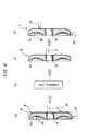
- Fig. 4 is a diagram showing a method for producing the input disc 4. This method is similar to a conventional method except the heat treatment described below. That is, first, a blank B is formed by cutting an annular material K of bearing steel for semi-high temperature obtained by casting, etc. At that time, as shown in Fig. 4(a), the raceway portion 4a with a concave curve surface is formed in one side of the annular material K by turning with cutting tools so as to provide machining allowance, and another side and the circumference are formed in predetermined shapes by turning so as to provide machining allowance. Additionally, a spline hole 4c with a plurality of strips of spline slots is formed in the center of the annular material by cutting with a broach 21.
- the blank B obtained in the cutting mentioned above is subjected to heat treatment (Fig. 4(b)).
- tempering is performed at the temperature of 250 °C or more after quenching at the temperature of 860 °C.
- the flanks of gear teeth of the spline hole 4c of the blank B are subjected to shaving by the broach 21 (Fig. 4(c)). After that, the raceway portion 4a of the one side, the circumference surface, and another side, etc. of the blank B is finished by turning (Fig. 4(d)). Thus, the input disc 4 can be obtained.
- a method for producing of the output disc 7 and the roller 13 is similar to a conventional method except that tempering temperature in the heat treatment is 250 °C or more.
- examples 3, 4 and comparative examples 4 6, subzero treatment is performed for 60 minutes at -70 °C after the heat treatment.
- the hardness is the value of HRC hardness calculated by the measurements of Vickers hardness.
- the life-test conditions are as follows:
- the amount of residual austenite in the range of depth Z 1.0L from the surface of the raceway portion, the hardness in the range, and the maximum oxide particle size according to the examples 1-4, in which the tempering was performed at the temperature 250 °C, were more than or equal to 7 wt % and less than or equal to 13 wt %, HRC 59.0-61.0, and 14-19 ⁇ m, respectively. As shown in the table 1, it is obvious that the life of these examples is improved 2.5-4.0 times as much as the comparative examples 1-6. In addition, the evaluation of life was based on the increase of vibrations in the testing equipment caused by the surface damage of the discs or the rollers.
- the whole of the input disc 4, the out put disc 7 and the rollers 13 are formed of the bearing steel for semi-high temperature, respectively.
- only the raceway portion 4a, 7a of each of the discs 4, 7 and the circumference portion 13a of the roller 13, which are rolling contact portions, can be formed of the bearing steel for semi-high temperature, respectively.
- at least one roller 13, which is subjected to relatively higher load among the plurality of rollers, can be formed of the bearing steel for semi-high temperature.
- toroidal-type continuously variable according to the above embodiment is described as a full-toroidal-type continuously variable transmission, it should be appreciated that the toroidal-type continuously variable according to the present invention can be applied to other toroidal-type continuously variable transmission.
Landscapes
- Engineering & Computer Science (AREA)
- Computer Networks & Wireless Communication (AREA)
- Signal Processing (AREA)
- General Engineering & Computer Science (AREA)
- Mechanical Engineering (AREA)
- Computer Security & Cryptography (AREA)
- Health & Medical Sciences (AREA)
- Computing Systems (AREA)
- General Health & Medical Sciences (AREA)
- Medical Informatics (AREA)
- Chemical & Material Sciences (AREA)
- Materials Engineering (AREA)
- Metallurgy (AREA)
- Organic Chemistry (AREA)
- Friction Gearing (AREA)
Abstract
Description

Claims (10)
- A toroidal-type continuously variable transmission comprising an input disc (4) having a concavely curved raceway portion (4a) in one side, an output disc (7) having a concavely curved raceway portion (7a) opposite to the raceway portion (4a) of the input disc (4) in one side, and a roller (13) rotatably sandwiched between the raceway portions (4a, 7a) of the discs (4, 7) for transmitting a torque between the discs (4, 7) by a traction force between the circumference of the roller (13) and the raceway portions (4a, 7a) of each of the discs (4, 7), wherein at least a rolling contact portion of at least one transmitting member of the input disc (4), the output disc (7) and the roller (13) is formed of a bearing steel which contains:wherein a residual austenite in a range of depth Z = 1.0L, where L is the major axis of a contact ellipse of the traction contact portion (A), from the surface of the rolling contact portion is 15 wt % or less, and the hardness of the range is HRC 58 to 62.C: 0.8 to 1.5 wt %; Si: 0.5 to 2.5 wt %; Mn: 0.3 to 2.0 wt %;Cr: 1.9 to 2.5 wt %; Mo: 0.3 to 1.0 wt %; and a total of 1.0 wt % or more of Si and Mo; with the balance being iron and unavoidable impurities;
- The transmission according to claim 1,
wherein an oxide particle size in the range of depth Z = 1.0L from the surface of the rolling contact portion formed of the bearing steel is less than 20 µm. - The transmission according to claim 1 or 2,
wherein an oxide particle size in a range of depth Z = 1.0b, where b is the minor axis of the contact ellipse of the traction contact portion (A), from the surface of the rolling contact portion formed of the bearing steel is less than 20 µm. - The transmission according to claim 1 or 2,
wherein an oxide particle size in a range of depth Z = 0.4b-0.5b, where b is the minor axis of the contact ellipse of the traction contact portion (A), from the surface of the rolling contact portion formed of the bearing steel is less than 20 µm. - The transmission according to claim 1 or 2,
wherein the whole of the input disc (4), the whole of the output disc (7), and the whole of the roller (13) are formed of the bearing steel, and the toroidal-type continuously variable transmission is a full-toroidal-type. - A toroidal-type continuously variable transmission comprising an input disc (4) having a concavely curved raceway portion (4a) in one side, an output disc (7) having a concavely curved raceway portion (7a) opposite to the raceway portion (4a) of the input disc (4) in one side, and a roller (13) rotatably sandwiched between the raceway portions (4a, 7a) of the discs (4, 7) for transmitting a torque between the discs (4, 7) by a traction force between the circumference of the roller (13) and the raceway portion (4a, 7a) of each of the discs (4, 7), wherein at least a rolling contact portion of at least one transmitting member of the input disc (4), the output disc (7) and the roller (13) is formed of a bearing steel which contains:wherein a residual austenite in a range of depth Z = 1.0L, where L is the major axis of a contact ellipse of the traction contact portion (A), from the surface of the rolling contact portion is 7 to 13 wt %, and the hardness of the range is HRC 59 to 61, and an oxide particle size in the range is 14 to 19 µm.C: 0.8 to 1.5 wt %; Si: 0.5 to 2.5 wt %; Mn: 0.3 to 2.0 wt %;Cr: 1.9 to 2.5 wt %; Mo: 0.3 to 1.0 wt %; and a total of 1.0 wt % or more of Si and Mo; with the balance being iron and unavoidable impurities;
- The transmission according to claim 6,
wherein an oxide particle size in the range of depth Z = 1.0b, where b is the minor axis of the contact ellipse of the traction contact portion (A), from the surface of the rolling contact portion formed of the bearing steel is less than 20 µm. - The transmission according to claim 6,
wherein an oxide particle size in the range of depth Z = 0.4b-0.5b, where b is the minor axis of the contact ellipse of the traction contact portion (A), from the surface of the rolling contact portion formed of the bearing steel is less than 20 µm. - The transmission according to any of claims 6 to 8,
wherein the whole of the input disc (4), the whole of the output disc (7), and the whole of the roller (13) are formed of the bearing steel, and the toroidal-type continuously variable transmission is a full-toroidal-type. - A method for producing a torque transmitting member according to any of claims 1 to 9, comprising the following steps:forming a predetermined shape of a blank (B) formed of the bearing steel;tempering the blank (B) at a temperature of 250 °C or more after quenching; andfinishing the heat-treated blank (B).
Applications Claiming Priority (2)
| Application Number | Priority Date | Filing Date | Title |
|---|---|---|---|
| JP2002202962A JP4075492B2 (en) | 2002-07-11 | 2002-07-11 | Method for manufacturing torque transmitting member of toroidal type continuously variable transmission |
| JP2002202962 | 2002-07-11 |
Publications (4)
| Publication Number | Publication Date |
|---|---|
| EP1380769A2 true EP1380769A2 (en) | 2004-01-14 |
| EP1380769A3 EP1380769A3 (en) | 2005-07-20 |
| EP1380769B1 EP1380769B1 (en) | 2008-08-20 |
| EP1380769B9 EP1380769B9 (en) | 2009-03-18 |
Family
ID=29728505
Family Applications (1)
| Application Number | Title | Priority Date | Filing Date |
|---|---|---|---|
| EP03015819A Expired - Lifetime EP1380769B9 (en) | 2002-07-11 | 2003-07-10 | Toroidal-type continuously variable transmission and method for producing torque transmitting member thereof |
Country Status (5)
| Country | Link |
|---|---|
| US (1) | US7488270B2 (en) |
| EP (1) | EP1380769B9 (en) |
| JP (1) | JP4075492B2 (en) |
| KR (1) | KR20040007281A (en) |
| DE (1) | DE60323012D1 (en) |
Cited By (1)
| Publication number | Priority date | Publication date | Assignee | Title |
|---|---|---|---|---|
| ITTO20120622A1 (en) * | 2012-07-13 | 2014-01-14 | Skf Ab | PROCEDURE FOR PROCESSING A VARIATOR DISC TO BE USED IN A TOROIDAL TRANSMISSION AT A CONTINUOUS VARIATION |
Families Citing this family (7)
| Publication number | Priority date | Publication date | Assignee | Title |
|---|---|---|---|---|
| US20070204940A1 (en) * | 2006-02-28 | 2007-09-06 | Jtekt Corporation | Rolling/sliding member, toroidal continuously variable transmission using the same method of manufacturing rolling/sliding member |
| US8152687B2 (en) | 2007-01-24 | 2012-04-10 | Torotrack (Development) Limited | Powdered metal variator components |
| US8176788B2 (en) * | 2008-12-08 | 2012-05-15 | The Boeing Company | System and method of ultrasonic inspection |
| GB0920546D0 (en) * | 2009-11-24 | 2010-01-06 | Torotrak Dev Ltd | Drive mechanism for infinitely variable transmission |
| JP2011208745A (en) * | 2010-03-30 | 2011-10-20 | Ntn Corp | Rolling bearing |
| JP5803878B2 (en) | 2012-11-05 | 2015-11-04 | トヨタ自動車株式会社 | Continuously variable transmission |
| JP2016041830A (en) * | 2013-01-15 | 2016-03-31 | 日産自動車株式会社 | Sliding resistant member and method of manufacturing sliding resistant member |
Family Cites Families (17)
| Publication number | Priority date | Publication date | Assignee | Title |
|---|---|---|---|---|
| JP3604415B2 (en) | 1993-08-31 | 2004-12-22 | 日本精工株式会社 | Toroidal continuously variable transmission |
| JPH07286649A (en) | 1994-04-18 | 1995-10-31 | Nippon Seiko Kk | Toroidal type continuously variable transmission |
| JP3385742B2 (en) | 1994-08-25 | 2003-03-10 | 日本精工株式会社 | Rolling bearing and method of manufacturing the same |
| JP2811059B2 (en) | 1995-10-20 | 1998-10-15 | 光洋精工株式会社 | Rolling bearing |
| JP2726990B2 (en) | 1996-05-28 | 1998-03-11 | 株式会社デンソー | Rolling bearing |
| JP3279230B2 (en) | 1997-09-02 | 2002-04-30 | 住友金属工業株式会社 | Bearing element part and method of manufacturing the same |
| JP2000282178A (en) * | 1998-10-22 | 2000-10-10 | Nsk Ltd | Rolling bearing |
| JP2000310307A (en) * | 1999-04-26 | 2000-11-07 | Koyo Seiko Co Ltd | Toroidal type continuously variable transmission |
| NL1012382C2 (en) * | 1999-06-17 | 2000-12-19 | Skf Eng & Res Centre Bv | Steel for rolling construction. |
| JP4022607B2 (en) | 1999-07-21 | 2007-12-19 | 日産自動車株式会社 | Manufacturing method of high surface pressure resistant member |
| JP2001032900A (en) | 1999-07-23 | 2001-02-06 | Nsk Ltd | Toroidal continuously variable transmission |
| JP3997662B2 (en) * | 1999-08-09 | 2007-10-24 | 株式会社ジェイテクト | Rolling bearing |
| JP2001152252A (en) | 1999-11-22 | 2001-06-05 | Nsk Ltd | Rolling bearing |
| JP4273609B2 (en) * | 2000-02-10 | 2009-06-03 | 日本精工株式会社 | Rolling bearing |
| JP2001280348A (en) * | 2000-03-28 | 2001-10-10 | Nsk Ltd | Rolling bearing |
| JP2001295847A (en) * | 2000-04-13 | 2001-10-26 | Nsk Ltd | Rolling device |
| JP2002188702A (en) * | 2000-12-25 | 2002-07-05 | Nissan Motor Co Ltd | Rolling element for continuously variable transmission and method of manufacturing the same |
-
2002
- 2002-07-11 JP JP2002202962A patent/JP4075492B2/en not_active Expired - Fee Related
-
2003
- 2003-07-09 KR KR1020030046370A patent/KR20040007281A/en not_active Ceased
- 2003-07-09 US US10/615,371 patent/US7488270B2/en active Active
- 2003-07-10 DE DE60323012T patent/DE60323012D1/en not_active Expired - Lifetime
- 2003-07-10 EP EP03015819A patent/EP1380769B9/en not_active Expired - Lifetime
Cited By (3)
| Publication number | Priority date | Publication date | Assignee | Title |
|---|---|---|---|---|
| ITTO20120622A1 (en) * | 2012-07-13 | 2014-01-14 | Skf Ab | PROCEDURE FOR PROCESSING A VARIATOR DISC TO BE USED IN A TOROIDAL TRANSMISSION AT A CONTINUOUS VARIATION |
| EP2684639A1 (en) * | 2012-07-13 | 2014-01-15 | Aktiebolaget SKF | A method for manufacturing a variator disc for use in a toroidal continuously variable transmission |
| US9132483B2 (en) | 2012-07-13 | 2015-09-15 | Aktiebolaget Skf | Method for manufacturing a variator disc for use in a toroidal continuously variable transmission |
Also Published As
| Publication number | Publication date |
|---|---|
| JP4075492B2 (en) | 2008-04-16 |
| KR20040007281A (en) | 2004-01-24 |
| EP1380769A3 (en) | 2005-07-20 |
| US20080009386A1 (en) | 2008-01-10 |
| EP1380769B9 (en) | 2009-03-18 |
| EP1380769B1 (en) | 2008-08-20 |
| JP2004044686A (en) | 2004-02-12 |
| DE60323012D1 (en) | 2008-10-02 |
| US7488270B2 (en) | 2009-02-10 |
Similar Documents
| Publication | Publication Date | Title |
|---|---|---|
| CN100532613C (en) | Rolling bearing | |
| US6440232B1 (en) | Toroidal-type continuously variable transmission | |
| US8118953B2 (en) | Method for producing steel part having long rolling contact fatigue life | |
| US7488270B2 (en) | Toroidal continuously variable transmission and method for producing torque transmitting member thereof | |
| EP3492759B1 (en) | Tapered roller bearing for automobile | |
| EP1187944B1 (en) | Rolling structure steel | |
| US6051080A (en) | Rolling element used for toroidal-type continuously variable transmission and method for producing same | |
| US6780139B2 (en) | Toroidal continuously variable transmission | |
| US6176806B1 (en) | Cam disk for toroidal type continuously variable transmission | |
| EP1190187B1 (en) | Cvt/ivt component | |
| JP7356035B2 (en) | Forging materials, forged parts and manufacturing methods thereof | |
| JP5957714B2 (en) | Pulley for continuously variable transmission and continuously variable transmission | |
| Ravikumar et al. | Analytical and numerical approach on design of cageless open differential unit | |
| JP4100072B2 (en) | Full toroidal continuously variable transmission | |
| JP4572797B2 (en) | V-belt type continuously variable transmission pulley disk and manufacturing method thereof | |
| EP1508724A2 (en) | Toroidal type continuously variable transmission | |
| EP1811052A1 (en) | Roll/slide member, toroidal continuously variable transmission utilizing the same, and process for producing roll/slide member | |
| JP5621338B2 (en) | Toroidal continuously variable transmission | |
| JPH08174340A (en) | Machine structural component excellent in surface fatigue strength and method for manufacturing the same | |
| JP2005076651A (en) | Rolling bearing and belt type continuously variable transmission using the same | |
| JP2003222218A (en) | Toroidal continuously variable transmission | |
| JP2001141010A (en) | Motive power transmission device for planetary roller | |
| JP2006283848A (en) | Toroidal continuously variable transmission | |
| JP2001153201A (en) | Planetary roller power transmission device | |
| JP2006194341A (en) | Toroidal continuously variable transmission |
Legal Events
| Date | Code | Title | Description |
|---|---|---|---|
| PUAI | Public reference made under article 153(3) epc to a published international application that has entered the european phase |
Free format text: ORIGINAL CODE: 0009012 |
|
| AK | Designated contracting states |
Kind code of ref document: A2 Designated state(s): AT BE BG CH CY CZ DE DK EE ES FI FR GB GR HU IE IT LI LU MC NL PT RO SE SI SK TR |
|
| AX | Request for extension of the european patent |
Extension state: AL LT LV MK |
|
| PUAL | Search report despatched |
Free format text: ORIGINAL CODE: 0009013 |
|
| AK | Designated contracting states |
Kind code of ref document: A3 Designated state(s): AT BE BG CH CY CZ DE DK EE ES FI FR GB GR HU IE IT LI LU MC NL PT RO SE SI SK TR |
|
| AX | Request for extension of the european patent |
Extension state: AL LT LV MK |
|
| RIC1 | Information provided on ipc code assigned before grant |
Ipc: 7C 21D 9/36 B Ipc: 7F 16H 15/38 A |
|
| 17P | Request for examination filed |
Effective date: 20050922 |
|
| AKX | Designation fees paid |
Designated state(s): DE FR GB IT |
|
| RAP1 | Party data changed (applicant data changed or rights of an application transferred) |
Owner name: JTEKT CORPORATION |
|
| GRAP | Despatch of communication of intention to grant a patent |
Free format text: ORIGINAL CODE: EPIDOSNIGR1 |
|
| GRAS | Grant fee paid |
Free format text: ORIGINAL CODE: EPIDOSNIGR3 |
|
| GRAA | (expected) grant |
Free format text: ORIGINAL CODE: 0009210 |
|
| AK | Designated contracting states |
Kind code of ref document: B1 Designated state(s): DE FR GB IT |
|
| REG | Reference to a national code |
Ref country code: GB Ref legal event code: FG4D |
|
| REF | Corresponds to: |
Ref document number: 60323012 Country of ref document: DE Date of ref document: 20081002 Kind code of ref document: P |
|
| PLBE | No opposition filed within time limit |
Free format text: ORIGINAL CODE: 0009261 |
|
| STAA | Information on the status of an ep patent application or granted ep patent |
Free format text: STATUS: NO OPPOSITION FILED WITHIN TIME LIMIT |
|
| 26N | No opposition filed |
Effective date: 20090525 |
|
| GBPC | Gb: european patent ceased through non-payment of renewal fee |
Effective date: 20090710 |
|
| PG25 | Lapsed in a contracting state [announced via postgrant information from national office to epo] |
Ref country code: GB Free format text: LAPSE BECAUSE OF NON-PAYMENT OF DUE FEES Effective date: 20090710 |
|
| PGFP | Annual fee paid to national office [announced via postgrant information from national office to epo] |
Ref country code: DE Payment date: 20100707 Year of fee payment: 8 Ref country code: FR Payment date: 20100805 Year of fee payment: 8 Ref country code: IT Payment date: 20100719 Year of fee payment: 8 |
|
| REG | Reference to a national code |
Ref country code: FR Ref legal event code: ST Effective date: 20120330 |
|
| PG25 | Lapsed in a contracting state [announced via postgrant information from national office to epo] |
Ref country code: DE Free format text: LAPSE BECAUSE OF NON-PAYMENT OF DUE FEES Effective date: 20120201 Ref country code: FR Free format text: LAPSE BECAUSE OF NON-PAYMENT OF DUE FEES Effective date: 20110801 |
|
| REG | Reference to a national code |
Ref country code: DE Ref legal event code: R119 Ref document number: 60323012 Country of ref document: DE Effective date: 20120201 |
|
| PG25 | Lapsed in a contracting state [announced via postgrant information from national office to epo] |
Ref country code: IT Free format text: LAPSE BECAUSE OF NON-PAYMENT OF DUE FEES Effective date: 20110710 |