EP1380449A2 - Trailing arm suspension - Google Patents
Trailing arm suspension Download PDFInfo
- Publication number
- EP1380449A2 EP1380449A2 EP03254314A EP03254314A EP1380449A2 EP 1380449 A2 EP1380449 A2 EP 1380449A2 EP 03254314 A EP03254314 A EP 03254314A EP 03254314 A EP03254314 A EP 03254314A EP 1380449 A2 EP1380449 A2 EP 1380449A2
- Authority
- EP
- European Patent Office
- Prior art keywords
- end portions
- trailing arms
- trailing
- suspension
- frame
- Prior art date
- Legal status (The legal status is an assumption and is not a legal conclusion. Google has not performed a legal analysis and makes no representation as to the accuracy of the status listed.)
- Withdrawn
Links
- 239000000725 suspension Substances 0.000 title claims abstract description 35
- 238000000034 method Methods 0.000 claims 4
- 238000004519 manufacturing process Methods 0.000 claims 1
- 239000006096 absorbing agent Substances 0.000 description 2
- 230000002411 adverse Effects 0.000 description 2
- 230000035939 shock Effects 0.000 description 2
- 238000005452 bending Methods 0.000 description 1
- 238000002485 combustion reaction Methods 0.000 description 1
- 239000002184 metal Substances 0.000 description 1
- 230000004048 modification Effects 0.000 description 1
- 238000012986 modification Methods 0.000 description 1
- 238000003466 welding Methods 0.000 description 1
Images
Classifications
-
- B—PERFORMING OPERATIONS; TRANSPORTING
- B60—VEHICLES IN GENERAL
- B60G—VEHICLE SUSPENSION ARRANGEMENTS
- B60G21/00—Interconnection systems for two or more resiliently-suspended wheels, e.g. for stabilising a vehicle body with respect to acceleration, deceleration or centrifugal forces
- B60G21/02—Interconnection systems for two or more resiliently-suspended wheels, e.g. for stabilising a vehicle body with respect to acceleration, deceleration or centrifugal forces permanently interconnected
- B60G21/04—Interconnection systems for two or more resiliently-suspended wheels, e.g. for stabilising a vehicle body with respect to acceleration, deceleration or centrifugal forces permanently interconnected mechanically
- B60G21/05—Interconnection systems for two or more resiliently-suspended wheels, e.g. for stabilising a vehicle body with respect to acceleration, deceleration or centrifugal forces permanently interconnected mechanically between wheels on the same axle but on different sides of the vehicle, i.e. the left and right wheel suspensions being interconnected
- B60G21/055—Stabiliser bars
- B60G21/0551—Mounting means therefor
-
- B—PERFORMING OPERATIONS; TRANSPORTING
- B60—VEHICLES IN GENERAL
- B60G—VEHICLE SUSPENSION ARRANGEMENTS
- B60G9/00—Resilient suspensions of a rigid axle or axle housing for two or more wheels
-
- B—PERFORMING OPERATIONS; TRANSPORTING
- B60—VEHICLES IN GENERAL
- B60G—VEHICLE SUSPENSION ARRANGEMENTS
- B60G2200/00—Indexing codes relating to suspension types
- B60G2200/30—Rigid axle suspensions
- B60G2200/314—Rigid axle suspensions with longitudinally arranged arms articulated on the axle
- B60G2200/315—Rigid axle suspensions with longitudinally arranged arms articulated on the axle at least one of the arms having an A or V shape
-
- B—PERFORMING OPERATIONS; TRANSPORTING
- B60—VEHICLES IN GENERAL
- B60G—VEHICLE SUSPENSION ARRANGEMENTS
- B60G2200/00—Indexing codes relating to suspension types
- B60G2200/30—Rigid axle suspensions
- B60G2200/34—Stabilising mechanisms, e.g. for lateral stability
- B60G2200/343—Stabilising mechanisms, e.g. for lateral stability with an axle suspended by two pivoted rods in "V"-arrangement, the rods being coupled at its apex
-
- B—PERFORMING OPERATIONS; TRANSPORTING
- B60—VEHICLES IN GENERAL
- B60G—VEHICLE SUSPENSION ARRANGEMENTS
- B60G2202/00—Indexing codes relating to the type of spring, damper or actuator
- B60G2202/10—Type of spring
- B60G2202/15—Fluid spring
- B60G2202/152—Pneumatic spring
-
- B—PERFORMING OPERATIONS; TRANSPORTING
- B60—VEHICLES IN GENERAL
- B60G—VEHICLE SUSPENSION ARRANGEMENTS
- B60G2204/00—Indexing codes related to suspensions per se or to auxiliary parts
- B60G2204/10—Mounting of suspension elements
- B60G2204/12—Mounting of springs or dampers
- B60G2204/122—Mounting of torsion springs
- B60G2204/1224—End mounts of stabiliser on wheel suspension
Definitions
- This invention relates to a trailing arm suspension system, and more particularly, the invention relates to an anti-roll bar suitable for a heavy duty trailing arm suspension system.
- Suspension systems utilize anti-roll bars to stabilize the vehicle during a turning maneuver.
- One conventional type of anti-roll bar utilized on passenger vehicles includes ends that are secured to a suspension component such as a lower control arm. A central portion extends between the ends and is supported on the frame of the vehicle by brackets and bushings. As the control arms move during a turning maneuver, the anti-roll bar rotationally deflects and acts against the frame to provide vehicle stability. Supporting an anti-roll bar by a frame for heavy duty vehicle applications is not practical since the suspension components may be spaced a significant distance from the frame so that a portion of the frame may not be located sufficiently close to the anti-roll bar.
- a heavy-duty trailing arm suspension system has been proposed that utilizes a torque tube extending between the trailing arms.
- the torque tube is welded to an adaptor plate that is supported by numerous bushings.
- the adaptor plate supports many other suspension components such as a shock absorber and/or air spring.
- the adaptor plate may also support the axle.
- the numerous bushings receive load inputs from various components. Accordingly, it is difficult to isolate any one bushing to optimize the roll characteristics.
- the present invention provides a trailing arm suspension for use in a heavy-duty vehicle.
- the suspension includes a frame and a pair of spaced apart trailing arms that each include a forward portion pivotally supported by the frame.
- the trailing arms extend longitudinally from the forward portion to a rearward portion.
- An anti-roll bar includes opposing end portions and a central portion transverse to and extending between the end portions.
- the end portions are respectively arranged longitudinally along a portion of the trailing arms and are pivotally secured respectively to the trailing arms.
- the end portions may be secured to the trailing arms by threaded fasteners and further supported on the trailing arm by a bracket having a bushing. At least a portion of the end portion is received in a pocket or channel in the trailing arm so that the end portion does not extend below the trailing arm.
- the above invention provides an anti-roll bar for a heavy duty trailing arm suspension system that is serviceable without adversely affecting the ground clearance of the suspension system.
- a heavy-duty suspension system is shown at 10 in Figures 1 and 2.
- the suspension 10 includes a frame 12 that may include any number of brackets 14 and other structural support members.
- the suspension 10 shown is suitable for use in such heavy-duty applications such as motor homes.
- the suspension 10 includes trailing arms 16 having forward portions 18 that arc secured to the brackets 14 at first pivotal connections 22 by threaded fasteners.
- the trailing arms 16 extend from the forward portions 18 to rearward portions 20.
- the trailing arm is preferably formed from a thick metal forming and attachment features welded to the arm.
- a combustion engine may be arranged rearward of the suspension 10 to provide rotational drive to the drive axle 23.
- An air spring 24 and shock absorber 26 may be arranged between the trailing arm 16 and the frame 12.
- An anti-roll bar 30 is arranged laterally between the trailing arm 16 and is preferably connected between the rearward portions 20.
- the bar 30 may include end portions 32 and a central portion 34 transverse to and extending between the end portions 32.
- the central portion 34 may be bent in any suitable shape.
- the trailing arm 16 may include a pocket 36 or channel opening downward and receiving the end portions 32.
- the end portions 32 extend longitudinally generally in the same longitudinal direction as the trailing arm 16.
- the end portions 32 are preferably located approximately beneath the air springs.
- the rearward portion 20 includes a terminal end 38 with the bar 30 preferably extending rearwardly beyond the terminal ends 38.
- the trailing arm 16 may include sidewalls 40 partially defining the pocket 36.
- the spaced apart bushings 42 may be received in the sidewalls 40 defining second pivotal connection 44.
- a threaded fastener is disposed within the bushings 42 to pivotally secure the end portions 32 to the trailing arms 16.
- the trailing arms 16 have a bottom surface 46 defining a lower plane.
- the bottom surface 46 may be lateral walls extending outwardly from the sidewalls 40 or the edges of the sidewalls.
- An anti-roll bar support plate 48 may include a portion spaced upwardly from the lower plane and secured to the trailing arm 16 by welding.
- Brackets 50 having flexible bushings 52 may additionally support the end portions 32 to the trailing arm 16.
- the brackets 50 may be secured to the trailing arms 16 by fasteners 54, as best shown in Figure 1.
- the brackets 50 are spaced rearwardly from the second pivotal connections 44.
- the anti-roll bar 30 may be serviced by moving the fasteners 44
- the present invention anti-roll bar configuration provides increased stiffness as compared to prior art configurations.
Landscapes
- Engineering & Computer Science (AREA)
- Mechanical Engineering (AREA)
- Vehicle Body Suspensions (AREA)
Abstract
Description
- This invention relates to a trailing arm suspension system, and more particularly, the invention relates to an anti-roll bar suitable for a heavy duty trailing arm suspension system. Suspension systems utilize anti-roll bars to stabilize the vehicle during a turning maneuver. One conventional type of anti-roll bar utilized on passenger vehicles includes ends that are secured to a suspension component such as a lower control arm. A central portion extends between the ends and is supported on the frame of the vehicle by brackets and bushings. As the control arms move during a turning maneuver, the anti-roll bar rotationally deflects and acts against the frame to provide vehicle stability. Supporting an anti-roll bar by a frame for heavy duty vehicle applications is not practical since the suspension components may be spaced a significant distance from the frame so that a portion of the frame may not be located sufficiently close to the anti-roll bar.
- A heavy-duty trailing arm suspension system has been proposed that utilizes a torque tube extending between the trailing arms. The torque tube is welded to an adaptor plate that is supported by numerous bushings. To service the torque tube, the adapted plate and all of the supported suspension components must be removed. The adaptor plate supports many other suspension components such as a shock absorber and/or air spring. The adaptor plate may also support the axle. As a result, the numerous bushings receive load inputs from various components. Accordingly, it is difficult to isolate any one bushing to optimize the roll characteristics.
- Therefore, what is needed is an anti-roll bar for a heavy duty trailing arm suspension system that is serviceable, without adversely affecting the ground clearance of the suspension system.
- The present invention provides a trailing arm suspension for use in a heavy-duty vehicle. The suspension includes a frame and a pair of spaced apart trailing arms that each include a forward portion pivotally supported by the frame. The trailing arms extend longitudinally from the forward portion to a rearward portion. An anti-roll bar includes opposing end portions and a central portion transverse to and extending between the end portions. The end portions are respectively arranged longitudinally along a portion of the trailing arms and are pivotally secured respectively to the trailing arms. The end portions may be secured to the trailing arms by threaded fasteners and further supported on the trailing arm by a bracket having a bushing. At least a portion of the end portion is received in a pocket or channel in the trailing arm so that the end portion does not extend below the trailing arm.
- Accordingly, the above invention provides an anti-roll bar for a heavy duty trailing arm suspension system that is serviceable without adversely affecting the ground clearance of the suspension system.
- Other advantages of the present invention can be understood by reference to the following detailed description when considered in connection with the accompanying drawings wherein:
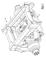
- Figure 1 is a top perspective view of a heavy duty trailing arm suspension system; and
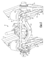
- Figure 2 is a bottom perspective view of the suspension system shown in Figure 1.
-
- A heavy-duty suspension system is shown at 10 in Figures 1 and 2. The
suspension 10 includes aframe 12 that may include any number ofbrackets 14 and other structural support members. Thesuspension 10 shown is suitable for use in such heavy-duty applications such as motor homes. Thesuspension 10 includes trailingarms 16 havingforward portions 18 that arc secured to thebrackets 14 at firstpivotal connections 22 by threaded fasteners. The trailingarms 16 extend from theforward portions 18 torearward portions 20. The trailing arm is preferably formed from a thick metal forming and attachment features welded to the arm. - An
axle 23, such as the drive axle shown, is pivotably supported on thetrailing arm 16 by brackets and pins (not shown). For motor home applications a combustion engine may be arranged rearward of thesuspension 10 to provide rotational drive to thedrive axle 23. Anair spring 24 andshock absorber 26 may be arranged between thetrailing arm 16 and theframe 12. - An
anti-roll bar 30 is arranged laterally between thetrailing arm 16 and is preferably connected between therearward portions 20. Thebar 30 may includeend portions 32 and acentral portion 34 transverse to and extending between theend portions 32. Thecentral portion 34 may be bent in any suitable shape. Thetrailing arm 16 may include apocket 36 or channel opening downward and receiving theend portions 32. Theend portions 32 extend longitudinally generally in the same longitudinal direction as thetrailing arm 16. Theend portions 32 are preferably located approximately beneath the air springs. Therearward portion 20 includes aterminal end 38 with thebar 30 preferably extending rearwardly beyond theterminal ends 38. - The
trailing arm 16 may includesidewalls 40 partially defining thepocket 36. The spaced apartbushings 42 may be received in thesidewalls 40 defining secondpivotal connection 44. A threaded fastener, best shown in Figure 1, is disposed within thebushings 42 to pivotally secure theend portions 32 to the trailingarms 16. The trailingarms 16 have abottom surface 46 defining a lower plane. Thebottom surface 46 may be lateral walls extending outwardly from thesidewalls 40 or the edges of the sidewalls. An anti-roll bar support plate 48 may include a portion spaced upwardly from the lower plane and secured to the trailingarm 16 by welding.Brackets 50 havingflexible bushings 52 may additionally support theend portions 32 to the trailingarm 16. Thebrackets 50 may be secured to the trailingarms 16 by fasteners 54, as best shown in Figure 1. Thebrackets 50 are spaced rearwardly from the secondpivotal connections 44. Theanti-roll bar 30 may be serviced by moving thefasteners 44 and 54. - During operation of the suspension such a turning maneuvers, the
end portions 32 undergo torsion. Thecentral portion 34 also undergoes torsion as well as bending. The present invention anti-roll bar configuration provides increased stiffness as compared to prior art configurations. - The invention has been described in an illustrative manner, and it is to be understood that the terminology that has been used is intended to be in the nature of words of description rather than of limitation. Obviously, many modifications and variations of the present invention are possible in light of the above teachings. It is, therefore, to be understood that within the scope of the appended claims the invention may be practiced otherwise than as specifically described.
Claims (13)
- A trailing arm suspension (10) for use in a heavy duty vehicle comprising:a frame (12);a pair of spaced apart trailing arms (16) each including a forward portion (18) pivotally supported by said frame and extending longitudinally to a rearward portion (20); andan anti-roll bar (30) having opposing end portions (32) and a central portion (34) transverse to and extending between said end portions, said end portions respectively arranged longitudinally along a portion of said trailing arms and pivotally secured respectively to said trailing arms.
- The suspension according to claim 1, wherein said rearward portions of said trailing arms includes a pocket (36) opening downward away from said frame with at least a portion of said end portions received in said pockets.
- The suspension according to claim 2, wherein said rearward portions includes side walls (40) at least partially defining said pockets with each side wall having a bushing (42) and a pivotal connection (44) disposed in said bushings supporting said end portions.
- The suspension according to claim 2 or 3, wherein said rearward portions includes a bottom surface (46) defining a lower plane with said end portions arranged above said lower planes.
- The suspension according to claim 4, wherein said rearward portions includes a support plate (48) having a portion spaced upwardly from said lower planes with a bracket (50) secured to said support plates supporting said end portions.
- The suspension according to claim 5, wherein said brackets includes a bushing (52) receiving said end portions.
- The suspension according to any preceding claim, wherein said suspension includes air springs (24) interposed between said frame and said trailing arms, said end portions arranged approximately beneath said air springs.
- The suspension according to any preceding claim, wherein said trailing arms include terminal ends (38) opposite said forward portion with said anti-roll bar extending beyond said terminal ends.
- A method of manufacturing a heavy-duty trailing arm suspension (10) comprising the steps of:a) securing trailing arms (16) to a frame (12) by first pivotal connections (22);b) securing end portions (32) of an anti-roll bar to the trailing arms by second pivotal connections (44); andc) securing the end portions to the trailing arms by brackets (50) spaced from the second pivotal connections.
- The method according to claim 9, wherein the securing of steps b) and c) utilizes threaded fasteners (54).
- The method according to claim 9 or 10, wherein the end portions extend longitudinally along the trailing arms.
- The method according to any one of claims 9 to 11, wherein bushings are welded to the trailing arms to receive the second pivotal connections.
- The method according to any one of claims 9 to 12, wherein a support plate (48) is welded to the trailing arms to receive the brackets.
Applications Claiming Priority (2)
| Application Number | Priority Date | Filing Date | Title |
|---|---|---|---|
| US194780 | 2002-07-12 | ||
| US10/194,780 US6871864B2 (en) | 2002-07-12 | 2002-07-12 | Trailing arm suspension anti-roll bar |
Publications (2)
| Publication Number | Publication Date |
|---|---|
| EP1380449A2 true EP1380449A2 (en) | 2004-01-14 |
| EP1380449A3 EP1380449A3 (en) | 2005-04-27 |
Family
ID=29735353
Family Applications (1)
| Application Number | Title | Priority Date | Filing Date |
|---|---|---|---|
| EP03254314A Withdrawn EP1380449A3 (en) | 2002-07-12 | 2003-07-08 | Trailing arm suspension |
Country Status (2)
| Country | Link |
|---|---|
| US (1) | US6871864B2 (en) |
| EP (1) | EP1380449A3 (en) |
Cited By (2)
| Publication number | Priority date | Publication date | Assignee | Title |
|---|---|---|---|---|
| CN105522884A (en) * | 2014-09-30 | 2016-04-27 | 比亚迪股份有限公司 | Chassis of passenger car |
| US11491838B2 (en) * | 2018-07-10 | 2022-11-08 | Iveco S.P.A. | Suspension for a vehicle |
Families Citing this family (14)
| Publication number | Priority date | Publication date | Assignee | Title |
|---|---|---|---|---|
| US7967307B2 (en) | 2002-07-12 | 2011-06-28 | Arvinmeritor Technology, Llc | Heavy duty trailing arm suspension system |
| ES2258374B1 (en) * | 2004-01-21 | 2007-11-16 | Automoviles Utilitarios, S.A. | SUSPENSION SYSTEM FOR VEHICLES. |
| US20050182039A1 (en) * | 2004-02-13 | 2005-08-18 | Bausch & Lomb Incorporated | Use of Loteprednol etabonate for the treatment of dry eye |
| US7503368B2 (en) | 2004-11-24 | 2009-03-17 | The Boeing Company | Composite sections for aircraft fuselages and other structures, and methods and systems for manufacturing such sections |
| GB0427302D0 (en) * | 2004-12-14 | 2005-01-19 | Oldbury Uk Ltd | Improvements in or relating to tandem wheel suspension systems |
| US7934579B2 (en) * | 2008-01-04 | 2011-05-03 | Honda Motor Company, Ltd. | Suspension assemblies having resilient member and vehicles including same |
| US7789405B2 (en) * | 2008-07-14 | 2010-09-07 | Link Manufacturing, Ltd. | Linkage-type air suspension system |
| US8465036B2 (en) | 2011-08-02 | 2013-06-18 | Arvinmeritor Technology, Llc | Side mounted air spring trailing arm suspension |
| US9004511B1 (en) * | 2013-10-09 | 2015-04-14 | Honda Motor Co., Ltd. | Stabilizing bar mounting structure |
| US10193838B2 (en) * | 2015-03-06 | 2019-01-29 | Microsoft Technology Licensing, Llc | Conditional instant delivery of email messages |
| GB2539695B (en) * | 2015-06-25 | 2019-12-18 | Ford Global Tech Llc | A bush and clamp assembly |
| US10967927B2 (en) | 2017-09-22 | 2021-04-06 | Link Mfg., Ltd. | Mounting brackets for auxiliary suspension systems |
| CA3226220A1 (en) | 2021-07-08 | 2023-01-12 | Link Mfg., Ltd. | Driven lift axles and associated systems and methods |
| US12611905B2 (en) | 2023-01-26 | 2026-04-28 | Link Mfg., Ltd | Tandem axle assembly and associated systems and methods |
Family Cites Families (10)
| Publication number | Priority date | Publication date | Assignee | Title |
|---|---|---|---|---|
| FR1425504A (en) * | 1964-12-10 | 1966-01-24 | Publicite Francaise | Vehicle rear suspension |
| US3406983A (en) * | 1966-11-25 | 1968-10-22 | Neway Equipment Co | Suspension for automotive vehicles |
| JPS5890814U (en) * | 1981-12-14 | 1983-06-20 | マツダ株式会社 | Automobile rear wheel suspension system |
| US4717171A (en) * | 1985-07-03 | 1988-01-05 | Honda Giken Kogyo Kabushiki Kaisha | Wheel suspension for road vehicles |
| US5039124A (en) * | 1989-11-06 | 1991-08-13 | Computer Design Chassis, Inc. | Motor vehicle frame and suspension assembly |
| MXPA00012632A (en) * | 1998-07-02 | 2002-07-02 | Boler Co | Trailing arm axle/suspension system. |
| DE60012370T2 (en) | 1999-11-24 | 2005-09-08 | Holland USA, Inc., Muskegon | trailing arm |
| CZ296802B6 (en) * | 2000-05-31 | 2006-06-14 | Benteler Ag | Twist-beam axle with transverse torsion bar |
| US6533300B1 (en) * | 2000-06-02 | 2003-03-18 | Oxford Suspension, Inc. | Trailing twist axle and method of manufacture |
| US6607205B2 (en) * | 2001-02-26 | 2003-08-19 | Meritor Heavy Vehicle Systems L.L.C. | Steerable independent air suspension system |
-
2002
- 2002-07-12 US US10/194,780 patent/US6871864B2/en not_active Expired - Lifetime
-
2003
- 2003-07-08 EP EP03254314A patent/EP1380449A3/en not_active Withdrawn
Non-Patent Citations (1)
| Title |
|---|
| None |
Cited By (3)
| Publication number | Priority date | Publication date | Assignee | Title |
|---|---|---|---|---|
| CN105522884A (en) * | 2014-09-30 | 2016-04-27 | 比亚迪股份有限公司 | Chassis of passenger car |
| CN105522884B (en) * | 2014-09-30 | 2018-05-29 | 比亚迪股份有限公司 | The chassis of car |
| US11491838B2 (en) * | 2018-07-10 | 2022-11-08 | Iveco S.P.A. | Suspension for a vehicle |
Also Published As
| Publication number | Publication date |
|---|---|
| US20040007844A1 (en) | 2004-01-15 |
| US6871864B2 (en) | 2005-03-29 |
| EP1380449A3 (en) | 2005-04-27 |
Similar Documents
| Publication | Publication Date | Title |
|---|---|---|
| US6871864B2 (en) | Trailing arm suspension anti-roll bar | |
| CA2536805C (en) | Rotary cam alignment system | |
| CN103140359B (en) | Axletree-the beam connection of heavy-duty vehicle | |
| US6550795B1 (en) | Suspension alignment device | |
| KR101124061B1 (en) | Frame integrated rear suspension | |
| US6733020B2 (en) | Suspension trailing arm | |
| EP2247455B1 (en) | Vehicle suspension assembly with unique geometry | |
| EP2282911B1 (en) | Dual leaf vehicle suspension with j-shaped spring element | |
| US7967307B2 (en) | Heavy duty trailing arm suspension system | |
| US6945547B2 (en) | Multi-link independent rear suspension assembly | |
| US9193236B2 (en) | Heavy-duty vehicle axle-to-beam or crossbrace-to-beam connection | |
| US9079467B2 (en) | Heavy-duty vehicle axle-to-beam or crossbrace-to-beam connection | |
| NZ526093A (en) | Vehicle suspension assembly | |
| US11207934B2 (en) | Vehicle suspension assembly | |
| US20020117829A1 (en) | Steerable independent air suspension system | |
| US6886840B2 (en) | Heavy duty trailing arm suspension system | |
| US6206391B1 (en) | Rear suspension using a torsional spring integral with trailing arm | |
| US12472787B2 (en) | Load equalizer assembly for tandem steer suspension | |
| US20050253352A1 (en) | Semi-trailing arm high cube rear suspension | |
| JP2005041402A (en) | Bracket structure | |
| US20070278759A1 (en) | Multiple trailing arm suspension | |
| JPH10167108A (en) | Cross member structure of vehicle | |
| JP2001039133A (en) | Suspension device | |
| CN107089110A (en) | A kind of automobile torsion beam suspension hind axle assembly | |
| JP2000079815A (en) | Automotive suspension equipment |
Legal Events
| Date | Code | Title | Description |
|---|---|---|---|
| PUAI | Public reference made under article 153(3) epc to a published international application that has entered the european phase |
Free format text: ORIGINAL CODE: 0009012 |
|
| AK | Designated contracting states |
Kind code of ref document: A2 Designated state(s): AT BE BG CH CY CZ DE DK EE ES FI FR GB GR HU IE IT LI LU MC NL PT RO SE SI SK TR |
|
| AX | Request for extension of the european patent |
Extension state: AL LT LV MK |
|
| PUAL | Search report despatched |
Free format text: ORIGINAL CODE: 0009013 |
|
| AK | Designated contracting states |
Kind code of ref document: A3 Designated state(s): AT BE BG CH CY CZ DE DK EE ES FI FR GB GR HU IE IT LI LU MC NL PT RO SE SI SK TR |
|
| AX | Request for extension of the european patent |
Extension state: AL LT LV MK |
|
| RIC1 | Information provided on ipc code assigned before grant |
Ipc: 7B 60G 11/27 B Ipc: 7B 60G 9/02 B Ipc: 7B 60G 7/00 B Ipc: 7B 60G 9/00 A |
|
| 17P | Request for examination filed |
Effective date: 20051010 |
|
| AKX | Designation fees paid |
Designated state(s): DE FR GB IT SE |
|
| 17Q | First examination report despatched |
Effective date: 20071114 |
|
| STAA | Information on the status of an ep patent application or granted ep patent |
Free format text: STATUS: THE APPLICATION IS DEEMED TO BE WITHDRAWN |
|
| 18D | Application deemed to be withdrawn |
Effective date: 20080326 |