EP1380328A1 - Heat integrated distillation column - Google Patents
Heat integrated distillation column Download PDFInfo
- Publication number
- EP1380328A1 EP1380328A1 EP03014973A EP03014973A EP1380328A1 EP 1380328 A1 EP1380328 A1 EP 1380328A1 EP 03014973 A EP03014973 A EP 03014973A EP 03014973 A EP03014973 A EP 03014973A EP 1380328 A1 EP1380328 A1 EP 1380328A1
- Authority
- EP
- European Patent Office
- Prior art keywords
- vapor
- distillation column
- section
- tube
- heat
- Prior art date
- Legal status (The legal status is an assumption and is not a legal conclusion. Google has not performed a legal analysis and makes no representation as to the accuracy of the status listed.)
- Granted
Links
Images



Classifications
-
- B—PERFORMING OPERATIONS; TRANSPORTING
- B01—PHYSICAL OR CHEMICAL PROCESSES OR APPARATUS IN GENERAL
- B01D—SEPARATION
- B01D3/00—Distillation or related exchange processes in which liquids are contacted with gaseous media, e.g. stripping
- B01D3/14—Fractional distillation or use of a fractionation or rectification column
- B01D3/143—Fractional distillation or use of a fractionation or rectification column by two or more of a fractionation, separation or rectification step
-
- B—PERFORMING OPERATIONS; TRANSPORTING
- B01—PHYSICAL OR CHEMICAL PROCESSES OR APPARATUS IN GENERAL
- B01D—SEPARATION
- B01D1/00—Evaporating
- B01D1/28—Evaporating with vapour compression
- B01D1/284—Special features relating to the compressed vapour
- B01D1/2856—The compressed vapour is used for heating a reboiler or a heat exchanger outside an evaporator
-
- B—PERFORMING OPERATIONS; TRANSPORTING
- B01—PHYSICAL OR CHEMICAL PROCESSES OR APPARATUS IN GENERAL
- B01D—SEPARATION
- B01D3/00—Distillation or related exchange processes in which liquids are contacted with gaseous media, e.g. stripping
- B01D3/04—Distillation or related exchange processes in which liquids are contacted with gaseous media, e.g. stripping pipe stills
-
- B—PERFORMING OPERATIONS; TRANSPORTING
- B01—PHYSICAL OR CHEMICAL PROCESSES OR APPARATUS IN GENERAL
- B01D—SEPARATION
- B01D3/00—Distillation or related exchange processes in which liquids are contacted with gaseous media, e.g. stripping
- B01D3/14—Fractional distillation or use of a fractionation or rectification column
- B01D3/32—Other features of fractionating columns ; Constructional details of fractionating columns not provided for in groups B01D3/16 - B01D3/30
- B01D3/322—Reboiler specifications
Definitions
- the present invention relates to a heat integrated distillation column which is constituted so that a multitube is coupled to a body shell via tube plates at both ends, thereby isolating a tube interior of each of the multitube from a tube exterior thereof within the body shell.
- Each tube interior and exterior is provided with inlets and outlets of gases and liquids.
- a difference is made in operating pressure between the tube interior and the tube exterior, so as to differentiate in operating temperature therebetween, and heat is transferred from a higher pressure side to a lower pressure side while using a wall of each of the multitube as a heat transfer surface, thereby performing functions of the higher pressure side as an enriching section and the lower pressure side as a stripping section.
- a heat integrated distillation column has been known as a process with a superior energy-saving property. It comprises a lower-pressure column and a higher-pressure column between which heat exchange is performed so as not to require heat to be supplied to or removed from the process. It is reasonable in principle and has been academically recognized that this process conforms to the most contributive theory of energy saving from the viewpoint of promoting energy efficiency for the distillation operation.
- a heat integrated distillation column in which a multitube is coupled to a body shell via tube plates at both ends, thereby isolating a tube interior of the multitube from a tube exterior thereof in an interior of the body shell.
- the tube interior and exterior is provided with inlets and outlets of gases and liquids.
- a difference is made in operating pressure between the tube interior and the tube exterior, so as to differentiate in operating temperature therebetween, and heat is transferred from a higher pressure side to a lower pressure side while using a wall of the multitube as a heat transfer surface, thereby constituting one distillation column with the use of the higher pressure side as an enriching section and the lower pressure side as a stripping section (Japanese Unexamined Patent Publication No. 8-66601).
- this heat integrated distillation column comprises a body shell 1, and a multitube (tube) 25 which is inserted into the body shell 1 and coupled to the body shell 1 via tube plates at both ends (an upper tube plate (a column top tube plate) 3a and a lower tube plate (a column bottom tube plate) 3b), so that a tube interior 4 of the multitube 25 is isolated from a tube exterior 5 thereof, and the tube interior 4 serves for an enriching section of a higher pressure side and the tube exterior 5 serves for a stripping section of a lower pressure side (alternatively, the tube interior 4 may serve for a stripping section of a lower pressure side and the tube exterior 5 may serve for an enriching section of a higher pressure side).
- the tube interior (the enriching section) 4 and the tube exterior (the stripping section) 5 are filled with packing.
- the upper portion of the body shell 1 is provided with a stripping-sect ion liquid inlet 6 for supplying liquid to the tube exterior (the stripping section) 5 and a stripping-section vapor outlet 7 for extracting vapor from the tube exterior (the stripping section) 5.
- An end chamber 14a communicating with the tube interior (the enriching section) 4 and above the column top tube plate 3a is provided with an enriching-section liquid inlet 8 for supplying liquid to the tube interior (the enriching section) 4 and an enriching-section vapor outlet 9 for extracting vapor from the tube interior (the enriching section) 4.
- the lower portion of the body shell 1 is provided with a stripping-section vapor inlet 10 for supplying vapor to the tube exterior (the stripping section) 5 and a stripping-section liquid outlet 11 for extracting liquid from the tube exterior (the stripping section) 5 .
- An end chamber 14b communicating with the tube interior (the enriching section) 4 and below the column bottom tube plate 3b is provided with an enriching-section vapor inlet 12 for supplying vapor to the tube interior (the enriching section) 4 and an enriching-section liquid outlet 13 for extracting liquid from the tube interior (the enriching section) 4.
- a solution at a temperature of the boiling point with respect to a concentration thereof is supplied to the column top of the stripping section 5 and column top vapor of the enriching section 4 is taken outside as a product.
- column top vapor of the stripping section 5 is supplied to the column bottom of the enriching section 4 of the higher pressure side via a compressor 21 and a part of column bottom liquid of the stripping section 5 is discharged to the outside as bottoms while the rest thereof is returned to the column bottom of the stripping section 5 via a reboiler 22.
- a predetermined quantity of column bottom liquid of the enriching section 4 is supplied to the stripping section 5 via a pressure reducing valve 23.
- the least energy consumption is obtained in the case where the quantity of vapor ascending at the top of the enriching section is equivalent to the quantity thereof (the yield) which is taken outside at the column as a top product.
- the minimum quantity of vapor ascending from the column bottom of the enriching section is calculated from a theoretical minimum reflux ratio.
- This minimum quantity of vapor is recognized to be the minimum quantity of vapor which is processed by the compressor with regard to a heat integrated distillation column typically constituted as shown in Fig. 2.
- While energy consumption of a general distillation column in which no heat exchange is performed consists merely of heat quantity which is consumed in the reboiler (energy consumption of heating source such as a steamer), a heat integrated distillation column requires the energy for driving the compressor in addition to heat quantity which is consumed in the reboiler.
- electric power is used as this energy for driving the compressor, and in the case of converting the electric power into heat quantity such as using a steamer, triplication of the electric power (kW) is supposed to be equivalent to the energy (kW) converted into heat quantity due to a low generating efficiency of the electric power.
- E energy consumption (heat quantity consumption (kW) in the reboiler) + 3 x (electric power consumption (kW) in the compressor).
- the compressor requires a high value of energy consumption so that the value occupies a great percentage in the whole energy consumption of a heat integrated distillation column. It is, therefore, a problem to have limitations on energy consumption effect of the whole heat integrated distillation column.
- the present invention is intended for solving the above-mentioned problem, and an object thereof is to provide a heat integrated distillation column in which less quantity of vapor processed by the compressor brings about less energy consumption in the compressor so as to decrease the whole energy consumption of a heat integrated distillation column.
- a heat integrated distillation column according to the present invention is characterized in that
- Another heat integrated distillation column according to the present invention is characterized in that
- a heat integrated distillation column since vapor after compressing vapor from the column top of the stripping section and vapor evaporated from a part of a solution are supplied to the column bottom of the enriching section, the energy is required for evaporating a part of the solution so as to increase the total quantity of vapor ascending in the enriching section. It is, however, possible to decrease the quantity of vapor to be compressed by a compressor, leading to the capability of promoting the energy saving for the whole heat integrated distillation column.
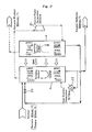
- Fig. 1 is a diagram showing constitution, current of gas and liquid, energy consumption and the like of a heat integrated distillation column according to an embodiment of the present invention. It should be noted that a basic constitution of this heat integrated distillation column is similar to that of a heat integrated distillation column shown in Figs. 4(a) and 4(b) and described in Background Art. Accordingly, a description of the basic constitution is herein omitted for avoiding duplication and instead the characteristics of the present invention are described referring to Fig. 1.
- a heat integrated distillation column is constituted so that heat is transferred from an enriching section 4 of a higher pressure side (such as a tube interior) to a stripping section 5 of a lower pressure side (such as a tube exterior), and a solution at a temperature of the boiling point with respect to a concentration thereof is supplied to the column top of the stripping section 5 and column top vapor of the enriching section 4 is taken outside as a product.
- a higher pressure side such as a tube interior
- a stripping section 5 of a lower pressure side such as a tube exterior
- the heat integrated distillation column is also constituted so that column top vapor of the stripping section 5 is supplied to the column bottom of the enriching section 4 of the higher pressure side via a compressor 21 and a part of column bottom liquid of the stripping section 5 is discharged to the outside as bottoms.
- the heat integrated distillation column according to this embodiment is provided with a heater (such as a steam heater) 24 for evaporating a part of a solution by heating and is also constituted so that vapor evaporated from a part of a solution by heating with the heater 24 is supplied to the column bottom of the enriching section 4 after separating mist therefrom in a gas-liquid separator 26, and the solution not evaporated is supplied to the column top of the stripping section 5 via a pressure reducing valve 23.
- a heater such as a steam heater
- Fig. 1 shows the quantity of gas and liquid ascending and descending in the enriching section 4 and the stripping section 5 as well as energy consumption (electric power consumption) in the compressor 21 and energy consumption (heat quantity consumption) in the heater 24 in the case where a solution consisting of 180 kmol/h of benzene and 180 kmol/h of toluene (360 kmol/h in total) is supplied to the heat integrated distillation column according to the above-mentioned embodiment so as to recover 180 kmol/h of benzene as a product and 180 kmol/h of toluene as bottoms.
- values of the quantity of gas and liquid put in parentheses are expressed in a unit of kmol/h.
- FIG. 2 shows the quantity of gas and liquid ascending and descending in the enriching section 4 and the stripping section 5 as well as energy consumption (electric power consumption) in the compressor 21 and energy consumption (heat quantity consumption) in a reboiler 22 in the case of a typical heat integrated distillation column described in Background Art, which is not provided with "a constitution such that vapor evaporated from a part of a solution is supplied to the column bottom of an enriching section".
- Fig. 3 shows the quantity of gas and liquid ascending and descending in the enriching section 4 and the stripping section 5 as well as energy consumption (heat quantity consumption) in the reboiler 22 in the case of a conventional distillation column in which no heat exchange is performed.
- energy consumption (heat quantity consumption) in the reboiler is 4000 kW with regard to the conventional distillation column in which no heat exchange is performed.
- energy consumption (heat quantity consumption) in the reboiler 22 is 1370 kW and electric power consumption in the compressor 21 is 360 kW with regard to the typical heat integrated distillation column which is not provided with a constitution such that vapor evaporated from a part of a solution is supplied to the column bottom of an enriching section.
- energy consumption (heat quantity consumption) in the heater 24 is 1240 kW and electric power consumption in the compressor 21 is 320 kW with regard to the heat integrated distillation column according to an embodiment of the present invention.
- the employment of the heat integrated distillation column according to the present invention namely, enables the effect of the energy saving to be improved from 38.7 % to 45.0 % as compared with the typical heat integrated distillation column which is not provided with a constitution such that vapor evaporated from a part of a solution is supplied to the column bottom of an enriching section.
- the present invention is applicable to a heat integrated distillation column which is constituted so as to use the tube interior as the stripping section, and a similar effect to the above-mentioned embodiment can be obtained also in that case.
Landscapes
- Chemical & Material Sciences (AREA)
- Chemical Kinetics & Catalysis (AREA)
- Vaporization, Distillation, Condensation, Sublimation, And Cold Traps (AREA)
Abstract
Description
- The present invention relates to a heat integrated distillation column which is constituted so that a multitube is coupled to a body shell via tube plates at both ends, thereby isolating a tube interior of each of the multitube from a tube exterior thereof within the body shell. Each tube interior and exterior is provided with inlets and outlets of gases and liquids. A difference is made in operating pressure between the tube interior and the tube exterior, so as to differentiate in operating temperature therebetween, and heat is transferred from a higher pressure side to a lower pressure side while using a wall of each of the multitube as a heat transfer surface, thereby performing functions of the higher pressure side as an enriching section and the lower pressure side as a stripping section.
- A heat integrated distillation column has been known as a process with a superior energy-saving property. It comprises a lower-pressure column and a higher-pressure column between which heat exchange is performed so as not to require heat to be supplied to or removed from the process. It is reasonable in principle and has been academically recognized that this process conforms to the most contributive theory of energy saving from the viewpoint of promoting energy efficiency for the distillation operation.
- In addition, a heat integrated distillation column has been suggested in which a multitube is coupled to a body shell via tube plates at both ends, thereby isolating a tube interior of the multitube from a tube exterior thereof in an interior of the body shell. The tube interior and exterior is provided with inlets and outlets of gases and liquids. A difference is made in operating pressure between the tube interior and the tube exterior, so as to differentiate in operating temperature therebetween, and heat is transferred from a higher pressure side to a lower pressure side while using a wall of the multitube as a heat transfer surface, thereby constituting one distillation column with the use of the higher pressure side as an enriching section and the lower pressure side as a stripping section (Japanese Unexamined Patent Publication No. 8-66601).
- As shown in Figs. 4(a) and (b), this heat integrated distillation column comprises a
body shell 1, and a multitube (tube) 25 which is inserted into thebody shell 1 and coupled to thebody shell 1 via tube plates at both ends (an upper tube plate (a column top tube plate) 3a and a lower tube plate (a column bottom tube plate) 3b), so that atube interior 4 of themultitube 25 is isolated from atube exterior 5 thereof, and thetube interior 4 serves for an enriching section of a higher pressure side and thetube exterior 5 serves for a stripping section of a lower pressure side (alternatively, thetube interior 4 may serve for a stripping section of a lower pressure side and thetube exterior 5 may serve for an enriching section of a higher pressure side). - In this heat integrated distillation column, the tube interior (the enriching section) 4 and the tube exterior (the stripping section) 5 are filled with packing. The upper portion of the
body shell 1 is provided with a stripping-sect ionliquid inlet 6 for supplying liquid to the tube exterior (the stripping section) 5 and a stripping-section vapor outlet 7 for extracting vapor from the tube exterior (the stripping section) 5. An end chamber 14a communicating with the tube interior (the enriching section) 4 and above the columntop tube plate 3a is provided with an enriching-sectionliquid inlet 8 for supplying liquid to the tube interior (the enriching section) 4 and an enriching-section vapor outlet 9 for extracting vapor from the tube interior (the enriching section) 4. - On the other hand, the lower portion of the
body shell 1 is provided with a stripping-section vapor inlet 10 for supplying vapor to the tube exterior (the stripping section) 5 and a stripping-sectionliquid outlet 11 for extracting liquid from the tube exterior (the stripping section) 5 . Anend chamber 14b communicating with the tube interior (the enriching section) 4 and below the columnbottom tube plate 3b is provided with an enriching-section vapor inlet 12 for supplying vapor to the tube interior (the enriching section) 4 and an enriching-sectionliquid outlet 13 for extracting liquid from the tube interior (the enriching section) 4. - In such a heat integrated distillation column, generally as shown in Fig. 2, a solution at a temperature of the boiling point with respect to a concentration thereof is supplied to the column top of the
stripping section 5 and column top vapor of the enrichingsection 4 is taken outside as a product. - Also, column top vapor of the
stripping section 5 is supplied to the column bottom of the enrichingsection 4 of the higher pressure side via acompressor 21 and a part of column bottom liquid of thestripping section 5 is discharged to the outside as bottoms while the rest thereof is returned to the column bottom of thestripping section 5 via areboiler 22. - Further, a predetermined quantity of column bottom liquid of the enriching
section 4 is supplied to thestripping section 5 via apressure reducing valve 23. - With regard to a heat integrated distillation column thus constituted, the least energy consumption is obtained in the case where the quantity of vapor ascending at the top of the enriching section is equivalent to the quantity thereof (the yield) which is taken outside at the column as a top product.
- In this case the minimum quantity of vapor ascending from the column bottom of the enriching section is calculated from a theoretical minimum reflux ratio. This minimum quantity of vapor is recognized to be the minimum quantity of vapor which is processed by the compressor with regard to a heat integrated distillation column typically constituted as shown in Fig. 2.
- While energy consumption of a general distillation column in which no heat exchange is performed consists merely of heat quantity which is consumed in the reboiler (energy consumption of heating source such as a steamer), a heat integrated distillation column requires the energy for driving the compressor in addition to heat quantity which is consumed in the reboiler. In general, electric power is used as this energy for driving the compressor, and in the case of converting the electric power into heat quantity such as using a steamer, triplication of the electric power (kW) is supposed to be equivalent to the energy (kW) converted into heat quantity due to a low generating efficiency of the electric power.
- Namely, energy consumption (E) of a heat integrated distillation column is represented by the following formula.
- Consequently, even if the quantity of vapor ascending from the column bottom of the enriching section is reduced to the minimum, the compressor requires a high value of energy consumption so that the value occupies a great percentage in the whole energy consumption of a heat integrated distillation column. It is, therefore, a problem to have limitations on energy consumption effect of the whole heat integrated distillation column.
- The present invention is intended for solving the above-mentioned problem, and an object thereof is to provide a heat integrated distillation column in which less quantity of vapor processed by the compressor brings about less energy consumption in the compressor so as to decrease the whole energy consumption of a heat integrated distillation column.
- In order to achieve the above-mentioned object, a heat integrated distillation column according to the present invention is characterized in that
- a multitube is coupled to a body shell via tube plates at both ends, thereby isolating a tube interior of each of the multitube from a tube exterior thereof in an interior of the body shell and providing each of the tube interior and the tube exterior with inlets and outlets of gas and liquid;
- a difference is made in operating pressure between the tube interior and the tube exterior, so as to differentiate in operating temperature therebetween, and heat is transferred from a higher pressure side to a lower pressure side while using a wall of each of the multitube as a heat transfer surface, thereby performing functions of the higher pressure side as an enriching section and the lower pressure side as a stripping section; and
- vapor after compressing vapor from a column top of the stripping section and vapor evaporated from a part of a solution are supplied to a column bottom of the enriching section.
- Another heat integrated distillation column according to the present invention is characterized in that
- vapor from the column top of the stripping section is compressed by a compressor and supplied to the column bottom of the enriching section, vapor evaporated from a part of a solution by heating with a heater is supplied to the column bottom of the enriching section, and the rest of the solution is supplied to the column top of the stripping section.
- In a heat integrated distillation column according to the present invention, since vapor after compressing vapor from the column top of the stripping section and vapor evaporated from a part of a solution are supplied to the column bottom of the enriching section, the energy is required for evaporating a part of the solution so as to increase the total quantity of vapor ascending in the enriching section. It is, however, possible to decrease the quantity of vapor to be compressed by a compressor, leading to the capability of promoting the energy saving for the whole heat integrated distillation column.
- As described in the present invention, namely, since vapor after compressing vapor from the column top of the stripping section by a compressor as well as vapor evaporated from a part of a solution by heating with a heater are supplied to the column bottom of the enriching section, energy consumption in the compressor is decreased more than energy consumption (heat quantity) required in the heater, leading to the capability of improving the effect of the energy saving for the whole heat integrated distillation column.
-
- Fig. 1
- is a diagram showing constitution, current of gas and liquid, energy consumption and the like of a heat integrated distillation column according to an embodiment of the present invention.
- Fig. 2
- is a diagram showing constitution, current of gas and liquid, energy consumption and the like of a typical heat integrated distillation column related to the present invention.
- Fig. 3
- is a diagram showing constitution, current of gas and liquid, energy consumption and the like of a conventional distillation column in which no heat exchange is performed.
- Fig. 4
- is a view showing a basic constitution of a typical heat integrated distillation column related to the present invention; (a) is a front cross sectional view, and (b) is a cross sectional view taken along a line b-b of (a).
- An embodiment of the present invention is described and the characteristics thereof are detailed hereinafter.
- Fig. 1 is a diagram showing constitution, current of gas and liquid, energy consumption and the like of a heat integrated distillation column according to an embodiment of the present invention. It should be noted that a basic constitution of this heat integrated distillation column is similar to that of a heat integrated distillation column shown in Figs. 4(a) and 4(b) and described in Background Art. Accordingly, a description of the basic constitution is herein omitted for avoiding duplication and instead the characteristics of the present invention are described referring to Fig. 1.
- A heat integrated distillation column according to this embodiment is constituted so that heat is transferred from an enriching
section 4 of a higher pressure side (such as a tube interior) to astripping section 5 of a lower pressure side (such as a tube exterior), and a solution at a temperature of the boiling point with respect to a concentration thereof is supplied to the column top of thestripping section 5 and column top vapor of the enrichingsection 4 is taken outside as a product. - The heat integrated distillation column is also constituted so that column top vapor of the
stripping section 5 is supplied to the column bottom of the enrichingsection 4 of the higher pressure side via acompressor 21 and a part of column bottom liquid of thestripping section 5 is discharged to the outside as bottoms. - The heat integrated distillation column according to this embodiment is provided with a heater (such as a steam heater) 24 for evaporating a part of a solution by heating and is also constituted so that vapor evaporated from a part of a solution by heating with the
heater 24 is supplied to the column bottom of the enrichingsection 4 after separating mist therefrom in a gas-liquid separator 26, and the solution not evaporated is supplied to the column top of thestripping section 5 via apressure reducing valve 23. - In the heat integrated distillation column according to this embodiment, as described above, since vapor after compressing vapor from the column top of the
stripping section 5 by thecompressor 21 is supplied to the column bottom of the enrichingsection 4 and additionally vapor evaporated from a part of a solution by heating is supplied to the column bottom of the enrichingsection 4, energy consumption (electric power consumption) in thecompressor 21 is decreased more than energy consumption (heat quantity consumption) required in theheater 24, leading to the capability of promoting the energy saving for the whole heat integrated distillation column. - Fig. 1 shows the quantity of gas and liquid ascending and descending in the enriching
section 4 and thestripping section 5 as well as energy consumption (electric power consumption) in thecompressor 21 and energy consumption (heat quantity consumption) in theheater 24 in the case where a solution consisting of 180 kmol/h of benzene and 180 kmol/h of toluene (360 kmol/h in total) is supplied to the heat integrated distillation column according to the above-mentioned embodiment so as to recover 180 kmol/h of benzene as a product and 180 kmol/h of toluene as bottoms. In Fig. 1, it should be noted that values of the quantity of gas and liquid put in parentheses are expressed in a unit of kmol/h. - For comparison, Fig. 2 shows the quantity of gas and liquid ascending and descending in the enriching
section 4 and thestripping section 5 as well as energy consumption (electric power consumption) in thecompressor 21 and energy consumption (heat quantity consumption) in areboiler 22 in the case of a typical heat integrated distillation column described in Background Art, which is not provided with "a constitution such that vapor evaporated from a part of a solution is supplied to the column bottom of an enriching section". - Also, Fig. 3 shows the quantity of gas and liquid ascending and descending in the enriching
section 4 and thestripping section 5 as well as energy consumption (heat quantity consumption) in thereboiler 22 in the case of a conventional distillation column in which no heat exchange is performed. - As shown in Fig. 3, energy consumption (heat quantity consumption) in the reboiler is 4000 kW with regard to the conventional distillation column in which no heat exchange is performed.
- Next, as shown in Fig. 2, energy consumption (heat quantity consumption) in the
reboiler 22 is 1370 kW and electric power consumption in thecompressor 21 is 360 kW with regard to the typical heat integrated distillation column which is not provided with a constitution such that vapor evaporated from a part of a solution is supplied to the column bottom of an enriching section. - In this case, energy consumption (E) of a heat integrated distillation column is expressed by the following formula:

- It is thus understood that the energy saving is achieved by 38.7 % of the conventional distillation column in which no heat exchange is performed (energy consumption is 4000 kW).
- Next, as shown in Fig. 1, energy consumption (heat quantity consumption) in the
heater 24 is 1240 kW and electric power consumption in thecompressor 21 is 320 kW with regard to the heat integrated distillation column according to an embodiment of the present invention. - In this case, energy consumption (E) of a heat integrated distillation column is expressed by the following formula:

- It is thus understood that the energy saving is achieved by 45.0 % of the conventional distillation column in which no heat exchange is performed (energy consumption is 4000 kW).
- The employment of the heat integrated distillation column according to the present invention, namely, enables the effect of the energy saving to be improved from 38.7 % to 45.0 % as compared with the typical heat integrated distillation column which is not provided with a constitution such that vapor evaporated from a part of a solution is supplied to the column bottom of an enriching section.
- In the heat integrated distillation column according to an embodiment of the present invention, since vapor evaporated from a part of a solution is supplied to an enriching section of a higher pressure side, electric power consumption in a solution pump for supplying a solution is increased to a certain extent. The increase thereof, however, remains within a negligible range as compared with the whole energy consumption of a heat integrated distillation column.
- The case of distilling a solution consisting of benzene and toluene is described as an example in the above-mentioned embodiment. It should be, however, noted that kinds of solutions are not particularly limited and the present invention is generally applicable to the case of distilling a solution consisting of various components.
- The case of using the tube exterior as the stripping section is described as an example in the above-mentioned embodiment. Alternatively, the present invention is applicable to a heat integrated distillation column which is constituted so as to use the tube interior as the stripping section, and a similar effect to the above-mentioned embodiment can be obtained also in that case.
- The present invention is not limited to the above-mentioned embodiment also in other points, and various applications and modifications can be made within the scope of the gist of the present invention.
Claims (2)
- A heat integrated distillation column, wherein a multitube is coupled to a body shell (1) via tube plates at both ends, thereby isolating a tube interior (4) of each of the multitube from a tube exterior (5) thereof in an interior of the body shell (1) and providing each of the tube interior (4) and the tube exterior (5) with inlets and outlets (6), (7), (8), (9), (10), (11), (12) and (13) of gas and liquid, a difference is made in operating pressure between the tube interior (4) and the tube exterior (5) to differentiate in operating temperature therebetween, and heat is transferred from a higher pressure side to a lower pressure side while using a wall of each of the multitube as a heat transfer surface, thereby performing functions of the higher pressure side as an enriching section and the lower pressure side as a stripping section; andvapor after compressing vapor from a column top of the stripping section (5) and vapor evaporated from a part of a solution are supplied to a column bottom of the enriching section (4).
- A heat integrated distillation column according to claim 1, wherein vapor from the column top of the stripping section (5) is compressed by a compressor (21) and supplied to the column bottom of the enriching section (4), vapor evaporated from a part of the solution by heating with a heater (24) is supplied to the column bottom of the enriching section (4), and the rest of the solution is supplied to the column top of the stripping section (5).
Applications Claiming Priority (2)
| Application Number | Priority Date | Filing Date | Title |
|---|---|---|---|
| JP2002191966 | 2002-07-01 | ||
| JP2002191966A JP2004033844A (en) | 2002-07-01 | 2002-07-01 | Internal heat exchange distillation column |
Publications (2)
| Publication Number | Publication Date |
|---|---|
| EP1380328A1 true EP1380328A1 (en) | 2004-01-14 |
| EP1380328B1 EP1380328B1 (en) | 2007-04-18 |
Family
ID=29728385
Family Applications (1)
| Application Number | Title | Priority Date | Filing Date |
|---|---|---|---|
| EP20030014973 Expired - Lifetime EP1380328B1 (en) | 2002-07-01 | 2003-07-01 | Heat integrated distillation column |
Country Status (3)
| Country | Link |
|---|---|
| EP (1) | EP1380328B1 (en) |
| JP (1) | JP2004033844A (en) |
| DE (1) | DE60313250T2 (en) |
Cited By (8)
| Publication number | Priority date | Publication date | Assignee | Title |
|---|---|---|---|---|
| CN101786048A (en) * | 2010-03-09 | 2010-07-28 | 中国矿业大学 | Mineral floatation technique |
| US7972423B2 (en) | 2005-04-28 | 2011-07-05 | Holm Christensen Biosystemer Aps | Rectification apparatus using a heat pump |
| WO2012047953A1 (en) * | 2010-10-06 | 2012-04-12 | Exxonmobil Research And Engineering Conpany | Low energy distillation system and method |
| EP2732859A1 (en) * | 2012-11-15 | 2014-05-21 | Toyo Engineering Corporation | Distillation apparatus and method for controlling the same |
| US20140346033A1 (en) * | 2011-09-22 | 2014-11-27 | Statoil Petroleum As | Regeneration of kinetic hydrate inhibitor |
| CN108007068A (en) * | 2018-01-07 | 2018-05-08 | 中国科学院工程热物理研究所 | A kind of LNG cold energy uses are thermally integrated rectifying space division system |
| CN111399573B (en) * | 2020-04-02 | 2021-07-23 | 中国航空工业集团公司北京长城计量测试技术研究所 | Temperature control cavity pressure measuring and controlling device |
| CN114470825A (en) * | 2022-02-10 | 2022-05-13 | 深圳市科伟达超声波设备有限公司 | Cleaning agent distillation retort and cleaning agent recovery unit |
Families Citing this family (6)
| Publication number | Priority date | Publication date | Assignee | Title |
|---|---|---|---|---|
| WO2009010250A2 (en) * | 2007-07-19 | 2009-01-22 | Frank Bahr | Method for controlling and cooling a distillation column |
| CN101874935B (en) * | 2010-07-05 | 2012-07-25 | 天津大学 | Rectifying section tower bottom reboiling internal heat-integrated energy-saving rectifying apparatus and method |
| CN101874934A (en) * | 2010-07-05 | 2010-11-03 | 天津大学 | Flash feed type internal heat integrated energy-saving rectification device and method |
| CN101966397B (en) * | 2010-09-16 | 2012-05-02 | 天津大学 | Energy-saving energy-saving rectification device and method in rectification column sequence |
| JP5923367B2 (en) * | 2012-03-30 | 2016-05-24 | 東洋エンジニアリング株式会社 | Heat exchange type distillation equipment |
| CN103585774B (en) * | 2012-08-17 | 2015-05-27 | 宏芳香料(昆山)有限公司 | Negative pressure steam heating apparatus and heating method thereof |
Citations (3)
| Publication number | Priority date | Publication date | Assignee | Title |
|---|---|---|---|---|
| US3959085A (en) * | 1973-01-02 | 1976-05-25 | Universal Oil Products Company | Fractionation apparatus having two integral and concentric fractionating units |
| US4681661A (en) * | 1983-10-14 | 1987-07-21 | Rakesh Govind | Dual distillation columns |
| EP0726085A1 (en) * | 1994-08-29 | 1996-08-14 | Kimura Chemical Plants Co., Ltd. | Internal heat exchange type distillation column |
-
2002
- 2002-07-01 JP JP2002191966A patent/JP2004033844A/en active Pending
-
2003
- 2003-07-01 EP EP20030014973 patent/EP1380328B1/en not_active Expired - Lifetime
- 2003-07-01 DE DE2003613250 patent/DE60313250T2/en not_active Expired - Lifetime
Patent Citations (3)
| Publication number | Priority date | Publication date | Assignee | Title |
|---|---|---|---|---|
| US3959085A (en) * | 1973-01-02 | 1976-05-25 | Universal Oil Products Company | Fractionation apparatus having two integral and concentric fractionating units |
| US4681661A (en) * | 1983-10-14 | 1987-07-21 | Rakesh Govind | Dual distillation columns |
| EP0726085A1 (en) * | 1994-08-29 | 1996-08-14 | Kimura Chemical Plants Co., Ltd. | Internal heat exchange type distillation column |
Cited By (13)
| Publication number | Priority date | Publication date | Assignee | Title |
|---|---|---|---|---|
| US7972423B2 (en) | 2005-04-28 | 2011-07-05 | Holm Christensen Biosystemer Aps | Rectification apparatus using a heat pump |
| CN101786048A (en) * | 2010-03-09 | 2010-07-28 | 中国矿业大学 | Mineral floatation technique |
| WO2012047953A1 (en) * | 2010-10-06 | 2012-04-12 | Exxonmobil Research And Engineering Conpany | Low energy distillation system and method |
| US20140346033A1 (en) * | 2011-09-22 | 2014-11-27 | Statoil Petroleum As | Regeneration of kinetic hydrate inhibitor |
| US9205346B2 (en) | 2012-11-15 | 2015-12-08 | Toyo Engineering Corporation | Distillation apparatus and method for controlling the same |
| CN103816691A (en) * | 2012-11-15 | 2014-05-28 | 东洋工程株式会社 | Distillation apparatus and method for controlling the same |
| EP2732859A1 (en) * | 2012-11-15 | 2014-05-21 | Toyo Engineering Corporation | Distillation apparatus and method for controlling the same |
| CN103816691B (en) * | 2012-11-15 | 2017-03-01 | 东洋工程株式会社 | Distilling apparatus and the method for controlling this distilling apparatus |
| CN108007068A (en) * | 2018-01-07 | 2018-05-08 | 中国科学院工程热物理研究所 | A kind of LNG cold energy uses are thermally integrated rectifying space division system |
| CN108007068B (en) * | 2018-01-07 | 2024-03-29 | 中国科学院工程热物理研究所 | Heat integration rectification air separation system for LNG cold energy utilization |
| CN111399573B (en) * | 2020-04-02 | 2021-07-23 | 中国航空工业集团公司北京长城计量测试技术研究所 | Temperature control cavity pressure measuring and controlling device |
| CN114470825A (en) * | 2022-02-10 | 2022-05-13 | 深圳市科伟达超声波设备有限公司 | Cleaning agent distillation retort and cleaning agent recovery unit |
| CN114470825B (en) * | 2022-02-10 | 2022-12-02 | 深圳市科伟达超声波设备有限公司 | Cleaning agent distillation retort and cleaning agent recovery unit |
Also Published As
| Publication number | Publication date |
|---|---|
| JP2004033844A (en) | 2004-02-05 |
| DE60313250D1 (en) | 2007-05-31 |
| EP1380328B1 (en) | 2007-04-18 |
| DE60313250T2 (en) | 2008-01-03 |
Similar Documents
| Publication | Publication Date | Title |
|---|---|---|
| EP1380328B1 (en) | Heat integrated distillation column | |
| US5980698A (en) | Method for vacuum distillation of a liquid product and an equipment for performing thereof | |
| US9205381B2 (en) | Method for dewatering water-containing organic substance | |
| CN111587147B (en) | Energy reuse system utilizing evaporative vapor recompressor within a combinatorial chemical process | |
| US5783047A (en) | Heat integrated distillation column | |
| US5964986A (en) | Distillation plant | |
| CN103068725B (en) | Method for concentrating an aqueous hydrogen peroxide solution | |
| US12180141B2 (en) | Process for the energy-efficient production of alkali metal alkoxides | |
| US7157610B2 (en) | Process for recovering methanol | |
| TW202106360A (en) | Process for distilling a crude composition in a rectification plant including an indirect heat pump | |
| US20040011048A1 (en) | Method of operating a combustion plant and a combustion plant | |
| CN102757019B (en) | A hydrogen peroxide concentration and purification system and method | |
| GB2457186A (en) | Installation for the distillation of drinking alcohol,especially whiskey | |
| EP0882480B1 (en) | Facility for distilling a liquid product | |
| US4421605A (en) | Distillation apparatus utilizing thermocompressor principles | |
| JP2018008986A (en) | Process and plant for the production of nitrobenzene | |
| JP2023161176A (en) | Ammonia aqueous solution distillation equipment | |
| JP4051457B2 (en) | Internal heat exchange distillation column | |
| CN101084176B (en) | Method for the recovery of methanol | |
| CN110746453B (en) | Production process and production device of dimethyl phosphite | |
| RU2095392C1 (en) | Installation for vacuum distillation of liquid product | |
| US20260132096A1 (en) | Improved process for production of alkali metal methoxides | |
| CN220513480U (en) | Organic matter residue separator | |
| JP7044458B1 (en) | Concentrator | |
| CN219328068U (en) | Pure steam generator |
Legal Events
| Date | Code | Title | Description |
|---|---|---|---|
| PUAI | Public reference made under article 153(3) epc to a published international application that has entered the european phase |
Free format text: ORIGINAL CODE: 0009012 |
|
| AK | Designated contracting states |
Kind code of ref document: A1 Designated state(s): AT BE BG CH CY CZ DE DK EE ES FI FR GB GR HU IE IT LI LU MC NL PT RO SE SI SK TR |
|
| AX | Request for extension of the european patent |
Extension state: AL LT LV MK |
|
| 17P | Request for examination filed |
Effective date: 20040203 |
|
| 17Q | First examination report despatched |
Effective date: 20040312 |
|
| AKX | Designation fees paid |
Designated state(s): DE |
|
| GRAP | Despatch of communication of intention to grant a patent |
Free format text: ORIGINAL CODE: EPIDOSNIGR1 |
|
| GRAS | Grant fee paid |
Free format text: ORIGINAL CODE: EPIDOSNIGR3 |
|
| GRAA | (expected) grant |
Free format text: ORIGINAL CODE: 0009210 |
|
| AK | Designated contracting states |
Kind code of ref document: B1 Designated state(s): DE |
|
| REF | Corresponds to: |
Ref document number: 60313250 Country of ref document: DE Date of ref document: 20070531 Kind code of ref document: P |
|
| PLBE | No opposition filed within time limit |
Free format text: ORIGINAL CODE: 0009261 |
|
| STAA | Information on the status of an ep patent application or granted ep patent |
Free format text: STATUS: NO OPPOSITION FILED WITHIN TIME LIMIT |
|
| 26N | No opposition filed |
Effective date: 20080121 |
|
| PGFP | Annual fee paid to national office [announced via postgrant information from national office to epo] |
Ref country code: DE Payment date: 20220530 Year of fee payment: 20 |
|
| REG | Reference to a national code |
Ref country code: DE Ref legal event code: R071 Ref document number: 60313250 Country of ref document: DE |