EP1378955A2 - Fuel cell - Google Patents
Fuel cell Download PDFInfo
- Publication number
- EP1378955A2 EP1378955A2 EP03012548A EP03012548A EP1378955A2 EP 1378955 A2 EP1378955 A2 EP 1378955A2 EP 03012548 A EP03012548 A EP 03012548A EP 03012548 A EP03012548 A EP 03012548A EP 1378955 A2 EP1378955 A2 EP 1378955A2
- Authority
- EP
- European Patent Office
- Prior art keywords
- gas
- diffusion layer
- fuel cell
- gas diffusion
- section
- Prior art date
- Legal status (The legal status is an assumption and is not a legal conclusion. Google has not performed a legal analysis and makes no representation as to the accuracy of the status listed.)
- Withdrawn
Links
- 239000000446 fuel Substances 0.000 title claims abstract description 41
- 238000009792 diffusion process Methods 0.000 claims abstract description 29
- 239000012528 membrane Substances 0.000 claims abstract description 26
- 239000003792 electrolyte Substances 0.000 claims abstract description 23
- 238000003487 electrochemical reaction Methods 0.000 claims abstract description 6
- 230000035699 permeability Effects 0.000 claims description 35
- 238000011144 upstream manufacturing Methods 0.000 claims description 35
- 239000000835 fiber Substances 0.000 claims description 24
- 238000010248 power generation Methods 0.000 claims description 9
- 230000003247 decreasing effect Effects 0.000 claims 1
- 239000007789 gas Substances 0.000 description 152
- 229920000049 Carbon (fiber) Polymers 0.000 description 16
- 239000004917 carbon fiber Substances 0.000 description 16
- 239000003054 catalyst Substances 0.000 description 11
- 238000006243 chemical reaction Methods 0.000 description 5
- 238000003475 lamination Methods 0.000 description 5
- VNWKTOKETHGBQD-UHFFFAOYSA-N methane Chemical compound C VNWKTOKETHGBQD-UHFFFAOYSA-N 0.000 description 5
- BASFCYQUMIYNBI-UHFFFAOYSA-N platinum Chemical compound [Pt] BASFCYQUMIYNBI-UHFFFAOYSA-N 0.000 description 4
- XLYOFNOQVPJJNP-UHFFFAOYSA-N water Substances O XLYOFNOQVPJJNP-UHFFFAOYSA-N 0.000 description 4
- UFHFLCQGNIYNRP-UHFFFAOYSA-N Hydrogen Chemical compound [H][H] UFHFLCQGNIYNRP-UHFFFAOYSA-N 0.000 description 3
- 238000010420 art technique Methods 0.000 description 3
- QVGXLLKOCUKJST-UHFFFAOYSA-N atomic oxygen Chemical compound [O] QVGXLLKOCUKJST-UHFFFAOYSA-N 0.000 description 3
- 239000001257 hydrogen Substances 0.000 description 3
- 229910052739 hydrogen Inorganic materials 0.000 description 3
- 239000001301 oxygen Substances 0.000 description 3
- 229910052760 oxygen Inorganic materials 0.000 description 3
- 239000005518 polymer electrolyte Substances 0.000 description 3
- 230000002411 adverse Effects 0.000 description 2
- 238000010276 construction Methods 0.000 description 2
- 238000010586 diagram Methods 0.000 description 2
- 239000000463 material Substances 0.000 description 2
- 229910052697 platinum Inorganic materials 0.000 description 2
- 239000012495 reaction gas Substances 0.000 description 2
- 239000007787 solid Substances 0.000 description 2
- 238000009825 accumulation Methods 0.000 description 1
- 239000011230 binding agent Substances 0.000 description 1
- 230000015572 biosynthetic process Effects 0.000 description 1
- 239000004020 conductor Substances 0.000 description 1
- 230000007423 decrease Effects 0.000 description 1
- 238000009826 distribution Methods 0.000 description 1
- 230000000694 effects Effects 0.000 description 1
- 238000012986 modification Methods 0.000 description 1
- 230000004048 modification Effects 0.000 description 1
- 239000002245 particle Substances 0.000 description 1
- 238000009827 uniform distribution Methods 0.000 description 1
Images



Classifications
-
- H—ELECTRICITY
- H01—ELECTRIC ELEMENTS
- H01M—PROCESSES OR MEANS, e.g. BATTERIES, FOR THE DIRECT CONVERSION OF CHEMICAL ENERGY INTO ELECTRICAL ENERGY
- H01M8/00—Fuel cells; Manufacture thereof
- H01M8/10—Fuel cells with solid electrolytes
- H01M8/1004—Fuel cells with solid electrolytes characterised by membrane-electrode assemblies [MEA]
-
- H—ELECTRICITY
- H01—ELECTRIC ELEMENTS
- H01M—PROCESSES OR MEANS, e.g. BATTERIES, FOR THE DIRECT CONVERSION OF CHEMICAL ENERGY INTO ELECTRICAL ENERGY
- H01M8/00—Fuel cells; Manufacture thereof
- H01M8/02—Details
- H01M8/0202—Collectors; Separators, e.g. bipolar separators; Interconnectors
-
- H—ELECTRICITY
- H01—ELECTRIC ELEMENTS
- H01M—PROCESSES OR MEANS, e.g. BATTERIES, FOR THE DIRECT CONVERSION OF CHEMICAL ENERGY INTO ELECTRICAL ENERGY
- H01M8/00—Fuel cells; Manufacture thereof
- H01M8/10—Fuel cells with solid electrolytes
- H01M8/1016—Fuel cells with solid electrolytes characterised by the electrolyte material
- H01M8/1018—Polymeric electrolyte materials
-
- Y—GENERAL TAGGING OF NEW TECHNOLOGICAL DEVELOPMENTS; GENERAL TAGGING OF CROSS-SECTIONAL TECHNOLOGIES SPANNING OVER SEVERAL SECTIONS OF THE IPC; TECHNICAL SUBJECTS COVERED BY FORMER USPC CROSS-REFERENCE ART COLLECTIONS [XRACs] AND DIGESTS
- Y02—TECHNOLOGIES OR APPLICATIONS FOR MITIGATION OR ADAPTATION AGAINST CLIMATE CHANGE
- Y02E—REDUCTION OF GREENHOUSE GAS [GHG] EMISSIONS, RELATED TO ENERGY GENERATION, TRANSMISSION OR DISTRIBUTION
- Y02E60/00—Enabling technologies; Technologies with a potential or indirect contribution to GHG emissions mitigation
- Y02E60/30—Hydrogen technology
- Y02E60/50—Fuel cells
Definitions
- This invention relates to the disposition of gas passages for a fuel cell.
- a polymer electrolyte fuel cell (PEFC) or a solid polymer electrolyte membrane fuel cell (PEMFC) are provided with a cathode and an anode comprising a platinum catalyst on the surface of an electrolyte membrane.
- the anode and the cathode are respectively covered by a gas diffusion layer (GDL).
- a separator is provided on the outer side of each GDL.
- a gas passage is formed in the separator facing the GDL.
- JP 11-016591 published by the Japanese Patent Office in 1999 discloses an arrangement in which the gas passage in the separator is divided into gas supply passages which supply reaction gas to the catalyst and gas discharge passages which discharge gas after reactions from the proximity of the catalyst.
- the gas supply passages and the gas discharge passages are disposed alternately and gas is supplied to the gas supply passages. This arrangement of the gas supply/discharge passages increases the reactive surface area and improves water discharge performance.
- this invention provides a fuel cell performing electric power generation according to an electro-chemical reaction of gas passing through an electrolyte membrane.
- the fuel cell comprises a gas diffusion layer facing the electrolyte membrane and a separator gripping the gas diffusion layer with the electrolyte membrane.
- a gas supply passage and a gas discharge passage are alternately formed in parallel to cause gas flow in mutually opposite directions.
- FIG. 1 is a sectional diagram of a fuel cell according to this invention.
- FIG. 2 is a schematic plan view of a part of a separator according to this invention.
- FIGs. 3A and 3B are cross sectional views of the separator taken along a line IIIA-IIIA and a line IIIB-IIIB in FIG. 2.
- FIG. 4 is a cross sectional view of a part of the separator taken along a line IV - IV in FIG. 2.
- FIG. 5 is similar to FIG. 2 but showing a second embodiment of this invention.
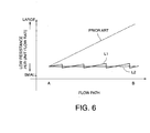
- FIG. 6 is a diagram showing the flow resistance in a gas diffusion layer according to the second embodiment of this invention.
- FIG. 7A and 7B are enlarged plan views of carbon fiber in the gas diffusion layer according to the second embodiment of this invention.
- a solid polymer electrolyte fuel cell according to this invention comprises a catalyst layer 7 formed on both sides of an electrolyte membrane 8 and a gas diffusion layer (GDL) 2 formed on the outer side of the catalyst layer 7.
- the electrolyte membrane 8, the catalyst layer 7 and the GDL 2 are integrated as a membrane electrode assembly (MEA).
- MEA membrane electrode assembly
- the membrane electrode assembly is sandwiched by a pair of separators 1 comprising a conductive material.
- Gas supply passages 5 are disposed alternately in parallel with gas discharge passages 6 in the separator 1 facing the GDL 2.
- the gas supply passage 5 and the gas discharge passage 6 for one separator 1 are disposed orthogonal with respect to the gas supply passage 5 and the gas discharge passage 6 of the other separator 1.
- each gas supply passage 5 is closed. The other end is connected to a gas supply manifold 3 formed in the separator 1. Reaction gas is supplied from the outside to the gas supply manifold 3.
- Each gas discharge passage 6 is partitioned from the adjacent gas supply passage 5 by a rib 10 which forms a part of the separator 1. One end of each gas discharge passage 6 is closed and the other end is connected to a gas discharge manifold 4.
- the gas discharge manifold 4 is disposed so that the direction of gas flow in the gas discharge passages 6 is opposite to the direction of gas flow in the gas supply passages 5. Specifically, an upstream section 5a of a gas supply passage 5 makes close contact with a downstream section 6b of an adjacent gas discharge passage 6.
- a downstream section 5b of the gas supply passage 5 makes close contact with an upstream section 6a of the gas discharge passage 6.
- the fuel cell is generally not used as a single unit but is used as a fuel cell stack comprising a plurality of laminated fuel cells.
- the dimensions with respect to the direction of stacking in the separator 1 must be constant. Therefore as shown in FIG. 4, the gas discharge manifold 4 and the gas supply manifold 3 are formed at divergent positions with respect to both the direction of stacking and the transverse direction in a range which allows for a certain separator thickness.
- the separator 1 is made of a plate 1A and a plate 1B laminated together.
- the gas supply manifold 3 and the gas discharge manifold 4 are respectively surrounded by a seal 12 to prevent leakage of gas.
- the above construction of the passages 5 and 6 allows gas supplied to the gas supply passage 5 to flow to the gas discharge passage 6 through the GDL 2 as shown in FIG. 4. More precisely, in the upstream section 5a of the gas supply passage 5, the gas permeating the GDL 2 flows to the downstream section 6b of the gas discharge passage 6. In the downstream section 5b of the gas supply passage 5, the gas permeating the GDL 2 flows to the upstream section 6a of the gas discharge passage 6.
- the gas in the downstream section 5b has higher moisture content than the gas in the upstream section 5a due to the fact that moisture produced in the GDL 2 is absorbed by the gas in the gas supply passage 5 when the gas flows from the upstream section 5a to the downstream section 5b.
- the direction of gas flow in the gas discharge passage 6 also means that moisture content of the gas in the downstream section 6b is higher than the gas in the upstream section 6a due to the fact that moisture produced in the GDL 2 is absorbed as the gas flows from the upstream section 6a to the downstream section 6b.
- the gas in the upstream section 5a in the gas supply passage which displays a low moisture content becomes mixed with the gas having a high moisture content flowing to the downstream section of the gas discharge passage 6.
- the gas in the downstream section 5b of the gas supply passage 5 which displays a high moisture content is mixed with the gas displaying a low moisture content flowing to the upstream section 6a of the gas discharge passage 6.
- gas in the upstream section of the gas supply passage which displays a low moisture content flows to the upstream section of the discharge passage and becomes mixed with gas having a low moisture content.
- Gas in the downstream section of the gas supply passage which has a high moisture content flows to the downstream section of the gas discharge passage and becomes mixed with gas having a high moisture content. This tends to suppress a water concentration gradient in the gas passage in the GDL 2 between the gas supply passage and the gas discharge passage. Consequently moisture is insufficient in the GDL 2 in the upstream section of the gas supply passage and the gas discharge passage and there is an excess of moisture in the GDL 2 in the downstream section of the gas supply passage and the gas discharge passage.
- the moisture concentration in the GDL 2 is made uniform by setting the direction of gas flow in the gas supply passage to be opposite to the direction of gas flow in the gas discharge passage, it is possible to prevent sections of the electrolyte membrane 8 from being insufficiently moisturized and to prevent the gas diffusion in the GDL 2 from being obstructed due to excessive moisture in the GDL 2.
- the power generation performance of the fuel cell can be improved.
- gas permeability in the GDL 2 is varied so that the pressure loss in a route A extending from the upstream section 5a of the gas supply passage 5 to the downstream section 6b of the gas discharge passage 6 differs from a route B extending from the downstream section 5b of the gas supply passage 5 to the upstream section 6a of the gas discharge passage 6.
- the route B for gas flow has a greater overall length in comparison to the route A and thus displays a larger overall pressure loss.
- the large amount of moisture present in the downstream section 5b of the gas supply passage 5 corresponding to the inlet of the route B inhibits gas flow into the route B.
- the flow rate per unit width of the GDL 2 for gas passing through the route B is smaller than the flow rate per unit width of the GDL 2 for gas passing through the route A.
- gas permeability in the GDL 2 increases progressively from the upstream section 5a to the downstream section 5b of the gas supply passage 5 in order to reduce the differential in the flow rate.
- This arrangement is enabled by combining a plurality of materials in the GDL which display different gas permeability.
- the structure of the fuel cell is the same as that described with reference to the first embodiment.
- FIG. 6 shows the flow resistance per unit gas flow amount in the GDL 2 from the route A to the route B.
- the broken line shows the prior art technique.
- the straight line L1 shows flow resistance when the gas permeability in the GDL 2 is varied in a stepwise manner.
- the straight line L2 shows flow resistance when the gas permeability in the GDL 2 is varied continuously.
- the GDL 2 is arranged in the following manner in order to vary the gas permeability in a continuous manner.
- the GDL 2 is formed by fixing carbon fibers disposed in a plane. It is possible to vary the gas permeability of the GDL 2 continuously by reducing the density of carbon fibers from the upstream section 5a to the downstream section 5b of the gas supply passage 5.
- the length of carbon fibers used in the GDL 2 generally ranges from 100 micrometers to 500 micrometers.
- the carbon fibers are mixed with a binder. However when performing the mixing operation, the carbon fibers are oriented in all directions and laminated with each other with a gap..
- long carbon fibers 11A are used as shown in FIG. 7A the gap between laminated fibers is larger than the situation in which short carbon fibers 11B are used as shown in FIG. 7B.
- the curve in the figure corresponds to the radius of the gap between the fibers.
- the section comprising 100-micrometer fibers displays lower gas permeability than a section using 500-micrometer fibers.
- the length of the carbon fibers used in the GDL 2 can be gradually increased from the upstream section 5a to the downstream section 5b of the gas supply passage 5. This allows the gas permeability of the GDL 2 to be continuously varied in a cost-effective structure.
- the gas permeability of the GDL 2 can be continuously varied in a cost-effective structure ⁇ B
- the fuel cell is used as a stack in which a plurality of fuel cells are laminated together in a series. When the fuel cells are laminated, a tightening pressure is applied with respect to the direction of lamination in order to ensure an effective seal for reaction gases and in order to reduce contact resistance between the electrolyte membrane 8 and the GDL 2.
- the GDL 2 having a constant thickness and displaying localized variation in the level of gas permeability has a portion of which the structural strength is relatively low due to high gas permeability. Such a portion may be damaged when the fuel cells are stacked and tightened. It is therefore preferable to apply high-strength fiber in the portion having a high gas permeability.
- the thickness of the GDL 2 is increased at positions displaying low gas permeability.
- gas permeability is increased as a result of increasing the diameter of the carbon fiber, the thickness of small diameter positions or positions displaying low gas permeability is greater than in other positions.
- tightening pressure is applied to the fuel cell with respect to the direction of lamination in order to ensure air-tight characteristics of the seal and in order to reduce the contact resistance between the GDL 2 and the catalyst layer 7.
- the pressure is applied in a uniform manner, sections in the GDL 2 comprising thin low-strength fibers are more likely to undergo large levels of compressive deformation than sections formed by thick high-strength fibers.
- the thickness of sections formed from thin fibers is adapted to be larger than other sections so that the thickness of the GDL 2 is constant when tightening pressure is applied with respect to the direction of lamination.
- a catalyst layer 7 is formed between the GDL 2 and the electrolyte membrane 8, but this invention can also be applied to fuel cells in which a catalyst is dispersed as particles within the GDL 2.
Landscapes
- Life Sciences & Earth Sciences (AREA)
- Engineering & Computer Science (AREA)
- Manufacturing & Machinery (AREA)
- Sustainable Development (AREA)
- Sustainable Energy (AREA)
- Chemical & Material Sciences (AREA)
- Chemical Kinetics & Catalysis (AREA)
- Electrochemistry (AREA)
- General Chemical & Material Sciences (AREA)
- Fuel Cell (AREA)
- Inert Electrodes (AREA)
Abstract
A fuel cell performs electro-chemical reactions of a gas passing through an
electrolyte membrane (8). A gas diffusion layer (2) is gripped between the electrolyte
membrane (8) and a separator (1). A gas supply passage (5) facing the gas
diffusion layer (2) and a gas discharge passage (6) facing the gas diffusion layer (2)
are disposed alternately in parallel in the separator (1). The moisture concentration
in the gas diffusion layer (2) is made uniform by adapting the direction of gas flow
in the gas supply passage (5) to be opposite to the direction of gas flow in the gas
discharge passage (6).
Description
This invention relates to the disposition of gas passages for a fuel cell.
A polymer electrolyte fuel cell (PEFC) or a solid polymer electrolyte
membrane fuel cell (PEMFC) are provided with a cathode and an anode comprising
a platinum catalyst on the surface of an electrolyte membrane. The anode and the
cathode are respectively covered by a gas diffusion layer (GDL). A separator is
provided on the outer side of each GDL. A gas passage is formed in the separator
facing the GDL.
When the fuel cell is generating power, hydrogen is supplied to the
anode by allowing flow of a gas containing hydrogen in the gas passage in one of
the separators. The cathode is supplied with oxygen by allowing flow of a gas
containing oxygen in the gas passage in the other separator. Power generation
operations are performed as a result of the following electro-chemical reactions
using a platinum catalyst. The electro-chemical reactions occur in the cathode
and the anode between the electrolyte membrane and the GDL.
anode: H2 → 2H+ +2e-
cathode: 2H+ + 2e- +12 O2 → H2 O
The accumulation of water produced by the reaction (2) above in
proximity to the surface of the electrolyte membrane inhibits the supply of the
hydrogen-containing gas to the anode and the supply of the oxygen-containing gas
to the cathode. This has adverse effects on the power generation performance of
the fuel cell. In a PEMFC, it is necessary to maintain the moisturisation of the
electrolyte membrane in order to ensure proton movement in the electrolyte
membrane. Power generation performance is adversely affected when the electrolyte
membrane becomes dry.
JP 11-016591 published by the Japanese Patent Office in 1999 discloses
an arrangement in which the gas passage in the separator is divided into gas
supply passages which supply reaction gas to the catalyst and gas discharge
passages which discharge gas after reactions from the proximity of the catalyst.
The gas supply passages and the gas discharge passages are disposed alternately
and gas is supplied to the gas supply passages. This arrangement of the gas
supply/discharge passages increases the reactive surface area and improves water
discharge performance.
In this prior art technique, there is a tendency for the electrolyte
membrane to dry out near to the inlet of the gas supply passages due to the fact
that the reactive gas does not contain water. As a result, there are large deviations
in the level of moisture across the electrolyte membrane and it is difficult to
obtain a preferred overall power generation efficiency in the fuel cell.
It is therefore an object of this invention to ensure a uniform distribution
of moisture in the GDL.
In order to achieve the above object, this invention provides a fuel cell
performing electric power generation according to an electro-chemical reaction of
gas passing through an electrolyte membrane.
The fuel cell comprises a gas diffusion layer facing the electrolyte
membrane and a separator gripping the gas diffusion layer with the electrolyte
membrane.
In the separator, a gas supply passage and a gas discharge passage are
alternately formed in parallel to cause gas flow in mutually opposite directions.
The details as well as other features and advantages of this invention
are set forth in the remainder of the specification and are shown in the accompanying
drawings.
FIG. 1 is a sectional diagram of a fuel cell according to this invention.
FIG. 2 is a schematic plan view of a part of a separator according to
this invention.
FIGs. 3A and 3B are cross sectional views of the separator taken along
a line IIIA-IIIA and a line IIIB-IIIB in FIG. 2.
FIG. 4 is a cross sectional view of a part of the separator taken along
a line IV - IV in FIG. 2.
FIG. 5 is similar to FIG. 2 but showing a second embodiment of this
invention.
FIG. 6 is a diagram showing the flow resistance in a gas diffusion
layer according to the second embodiment of this invention.
FIG. 7A and 7B are enlarged plan views of carbon fiber in the gas
diffusion layer according to the second embodiment of this invention.
Referring to FIG. 1 of the drawings, a solid polymer electrolyte fuel cell
according to this invention comprises a catalyst layer 7 formed on both sides of an
electrolyte membrane 8 and a gas diffusion layer (GDL) 2 formed on the outer side
of the catalyst layer 7. The electrolyte membrane 8, the catalyst layer 7 and the
GDL 2 are integrated as a membrane electrode assembly (MEA). The membrane
electrode assembly is sandwiched by a pair of separators 1 comprising a conductive
material. Gas supply passages 5 are disposed alternately in parallel with gas
discharge passages 6 in the separator 1 facing the GDL 2. The gas supply passage
5 and the gas discharge passage 6 for one separator 1 are disposed orthogonal with
respect to the gas supply passage 5 and the gas discharge passage 6 of the other
separator 1.
Referring now to FIGs. 2 - 4, one end of each gas supply passage 5 is
closed. The other end is connected to a gas supply manifold 3 formed in the
separator 1. Reaction gas is supplied from the outside to the gas supply manifold
3. Each gas discharge passage 6 is partitioned from the adjacent gas supply
passage 5 by a rib 10 which forms a part of the separator 1. One end of each gas
discharge passage 6 is closed and the other end is connected to a gas discharge
manifold 4.
As shown in FIG. 2, the gas discharge manifold 4 is disposed so that
the direction of gas flow in the gas discharge passages 6 is opposite to the
direction of gas flow in the gas supply passages 5. Specifically, an upstream
section 5a of a gas supply passage 5 makes close contact with a downstream
section 6b of an adjacent gas discharge passage 6.
A downstream section 5b of the gas supply passage 5 makes close
contact with an upstream section 6a of the gas discharge passage 6.
Consequently it is necessary to form the gas discharge manifold 4 in
proximity to the gas supply manifold 3. The fuel cell is generally not used as a
single unit but is used as a fuel cell stack comprising a plurality of laminated fuel
cells. Thus the dimensions with respect to the direction of stacking in the
separator 1 must be constant. Therefore as shown in FIG. 4, the gas discharge
manifold 4 and the gas supply manifold 3 are formed at divergent positions with
respect to both the direction of stacking and the transverse direction in a range
which allows for a certain separator thickness. In order to realize such a construction,
it is preferable that the separator 1 is made of a plate 1A and a plate 1B laminated
together. The gas supply manifold 3 and the gas discharge manifold 4 are respectively
surrounded by a seal 12 to prevent leakage of gas.
The above construction of the passages 5 and 6 allows gas supplied to
the gas supply passage 5 to flow to the gas discharge passage 6 through the GDL 2
as shown in FIG. 4. More precisely, in the upstream section 5a of the gas supply
passage 5, the gas permeating the GDL 2 flows to the downstream section 6b of
the gas discharge passage 6. In the downstream section 5b of the gas supply
passage 5, the gas permeating the GDL 2 flows to the upstream section 6a of the
gas discharge passage 6.
With respect to gas flow in the gas supply passage 5, the gas in the
downstream section 5b has higher moisture content than the gas in the upstream
section 5a due to the fact that moisture produced in the GDL 2 is absorbed by the
gas in the gas supply passage 5 when the gas flows from the upstream section 5a
to the downstream section 5b. The direction of gas flow in the gas discharge
passage 6 also means that moisture content of the gas in the downstream section
6b is higher than the gas in the upstream section 6a due to the fact that moisture
produced in the GDL 2 is absorbed as the gas flows from the upstream section 6a
to the downstream section 6b.
In this fuel cell, since the direction of flow in the gas supply passage 5
is opposite to the direction of flow in the gas discharge passage 6, the gas in the
upstream section 5a in the gas supply passage which displays a low moisture
content becomes mixed with the gas having a high moisture content flowing to the
downstream section of the gas discharge passage 6. The gas in the downstream
section 5b of the gas supply passage 5 which displays a high moisture content is
mixed with the gas displaying a low moisture content flowing to the upstream
section 6a of the gas discharge passage 6.
As a result, in the GDL 2, a moisture concentration gradient is
produced between the upstream section 5a and the downstream section 6b and
between the downstream section 5b and the upstream section 6b. Consequently
moisture in the GDL 2 migrates from the downstream section 6b towards the
upstream section 5a and from the downstream section 5b towards the upstream
section 6a. As a result, the moisture concentration in the GDL 2 becomes
uniform.
In the prior art technique, gas in the upstream section of the gas
supply passage which displays a low moisture content flows to the upstream
section of the discharge passage and becomes mixed with gas having a low moisture
content. Gas in the downstream section of the gas supply passage which has a
high moisture content flows to the downstream section of the gas discharge
passage and becomes mixed with gas having a high moisture content. This tends
to suppress a water concentration gradient in the gas passage in the GDL 2
between the gas supply passage and the gas discharge passage. Consequently
moisture is insufficient in the GDL 2 in the upstream section of the gas supply
passage and the gas discharge passage and there is an excess of moisture in the
GDL 2 in the downstream section of the gas supply passage and the gas discharge
passage.
According to this invention, since the moisture concentration in the
GDL 2 is made uniform by setting the direction of gas flow in the gas supply
passage to be opposite to the direction of gas flow in the gas discharge passage, it
is possible to prevent sections of the electrolyte membrane 8 from being insufficiently
moisturized and to prevent the gas diffusion in the GDL 2 from being obstructed
due to excessive moisture in the GDL 2. Thus the power generation performance of
the fuel cell can be improved.
Referring to FIG. 5, a second embodiment of this invention will be
described.
In this embodiment, gas permeability in the GDL 2 is varied so that
the pressure loss in a route A extending from the upstream section 5a of the gas
supply passage 5 to the downstream section 6b of the gas discharge passage 6
differs from a route B extending from the downstream section 5b of the gas supply
passage 5 to the upstream section 6a of the gas discharge passage 6.
The route B for gas flow has a greater overall length in comparison to
the route A and thus displays a larger overall pressure loss. In contrast, the large
amount of moisture present in the downstream section 5b of the gas supply
passage 5 corresponding to the inlet of the route B inhibits gas flow into the route
B. Thus the flow rate per unit width of the GDL 2 for gas passing through the
route B is smaller than the flow rate per unit width of the GDL 2 for gas passing
through the route A.
In this embodiment, gas permeability in the GDL 2 increases progressively
from the upstream section 5a to the downstream section 5b of the gas supply
passage 5 in order to reduce the differential in the flow rate. This arrangement is
enabled by combining a plurality of materials in the GDL which display different
gas permeability. In other respects, the structure of the fuel cell is the same as
that described with reference to the first embodiment.
According to this embodiment, since gas flow from the gas supply
passage 5 through the GDL 2 to the gas discharge passage 6 through the GDL 2 is
uniform, moisture discharge performance for moisture produced in the GDL 2 is
uniform. Furthermore since gas passing through the GDL 2 comes into contact
with the catalyst layer 7 when performing electro-chemical reactions, a uniform
flow rate distribution in the GDL 2 improves reaction performance. These
improvements in the uniformity of discharge performance and the improvement in
the reaction efficiency improve the power generation performance of the fuel cell.
Instead of varying the gas permeability in the GDL 2 progressively, it
is possible to make further improvement to power generation efficiency and to
increase the uniformity of the flow rate of gas in the GDL 2 by employing a GDL
material which varies the gas permeability continuously. FIG. 6 shows the flow
resistance per unit gas flow amount in the GDL 2 from the route A to the route B.
The broken line shows the prior art technique. The straight line L1 shows flow
resistance when the gas permeability in the GDL 2 is varied in a stepwise manner.
The straight line L2 shows flow resistance when the gas permeability in the GDL 2
is varied continuously.
The GDL 2 is arranged in the following manner in order to vary the
gas permeability in a continuous manner. The GDL 2 is formed by fixing carbon
fibers disposed in a plane. It is possible to vary the gas permeability of the GDL 2
continuously by reducing the density of carbon fibers from the upstream section
5a to the downstream section 5b of the gas supply passage 5.
Alternatively as shown in FIG. 7A and 7B, it is possible to vary gas
permeability by varying the length of the carbon fibers. In other words, it is
possible to increase gas permeability by using long carbon fibers. The length of
carbon fibers used in the GDL 2 generally ranges from 100 micrometers to 500
micrometers. The carbon fibers are mixed with a binder. However when performing
the mixing operation, the carbon fibers are oriented in all directions and laminated
with each other with a gap.. As a result, when long carbon fibers 11A are used as
shown in FIG. 7A the gap between laminated fibers is larger than the situation in
which short carbon fibers 11B are used as shown in FIG. 7B. The curve in the
figure corresponds to the radius of the gap between the fibers. Thus the section
comprising 100-micrometer fibers displays lower gas permeability than a section
using 500-micrometer fibers.
The length of the carbon fibers used in the GDL 2 can be gradually
increased from the upstream section 5a to the downstream section 5b of the gas
supply passage 5. This allows the gas permeability of the GDL 2 to be continuously
varied in a cost-effective structure.
Alternatively it is possible to vary the gas permeability by varying the
diameter of the carbon fiber. The formation of a large gap between the fibers is
facilitated by increasing the diameter of the carbon fibers.
When the fibers of a large diameter are used to form the GDL, a large
gap is likely to be formed between adjacent fibers, which decreases the fiber
density per unit volume of the GDL, and increases as a result the gas permeability
of GDL.
By gradually increasing the diameter of carbon fiber used for forming
GDL 2 from upstream section 5a towards the downstream section 5b of the gas
supply passage 5, the gas permeability of the GDL 2 can be continuously varied in
a cost-effective structureÅB
When the gas permeability of the GDL 2 is varied by varying the
dimensions of the gap or the density of the carbon fiber, there is the possibility
that the strength of the GDL 2 in sections displaying high gas permeability will be
reduced. The fuel cell is used as a stack in which a plurality of fuel cells are
laminated together in a series. When the fuel cells are laminated, a tightening
pressure is applied with respect to the direction of lamination in order to ensure
an effective seal for reaction gases and in order to reduce contact resistance
between the electrolyte membrane 8 and the GDL 2.
The GDL 2 having a constant thickness and displaying localized variation
in the level of gas permeability has a portion of which the structural strength is
relatively low due to high gas permeability. Such a portion may be damaged when
the fuel cells are stacked and tightened. It is therefore preferable to apply high-strength
fiber in the portion having a high gas permeability.
In this manner, it is possible to maintain the seal characteristics
during lamination of the fuel cell and to maintain the contact resistance between
the GDL 2 and the electrolyte membrane 8 to a preferred level while at the same
time preventing damage to the fuel cell as a result of the tightening pressure.
Alternatively it is preferred that the thickness of the GDL 2 is increased
at positions displaying low gas permeability. When gas permeability is increased
as a result of increasing the diameter of the carbon fiber, the thickness of small
diameter positions or positions displaying low gas permeability is greater than in
other positions. When the fuel cell is laminated, tightening pressure is applied to
the fuel cell with respect to the direction of lamination in order to ensure air-tight
characteristics of the seal and in order to reduce the contact resistance between
the GDL 2 and the catalyst layer 7. When the pressure is applied in a uniform
manner, sections in the GDL 2 comprising thin low-strength fibers are more likely
to undergo large levels of compressive deformation than sections formed by thick
high-strength fibers. Thus the thickness of sections formed from thin fibers is
adapted to be larger than other sections so that the thickness of the GDL 2 is
constant when tightening pressure is applied with respect to the direction of
lamination.
Thus it is possible to maintain the contact resistance between the
GDL 2 and the electrolyte membrane 8 or the seal characteristics during lamination
of the fuel cell to a preferred level. Furthermore it is possible to prevent the
tightening pressure from damaging the fuel cell.
The contents of Tokugan 2002-197115, with a filing date of July 5,
2002 in Japan, are hereby incorporated by reference.
Although the invention has been described above by reference to certain
embodiments of the invention, the invention is not limited to the embodiments
described above. Modifications and variations of the embodiments described above
will occur to those skilled in the art, in light of the above teachings.
For example, in each of the above embodiments, a catalyst layer 7 is
formed between the GDL 2 and the electrolyte membrane 8, but this invention can
also be applied to fuel cells in which a catalyst is dispersed as particles within the
GDL 2.
The embodiments of this invention in which an exclusive property or
privilege is claimed are defined as follows:
Claims (11)
- A fuel cell performing electric power generation according to an electro-chemical reaction of gas passing through an electrolyte membrane, comprising:a gas diffusion layer (2) facing the electrolyte membrane (8); anda separator (1) gripping the gas diffusion layer (2) with the electrolyte membrane (8), a gas supply passage (5) and a gas discharge passage (6) being alternately formed in parallel in the separator (1) to cause gas flow in mutually opposite directions.
- The fuel cell as defined in Claim 1, wherein the gas diffusion layer (2) has an upstream section and a downstream section with respect to a flow of gas in the gas supply passage (5), and a gas permeability of the upstream section is set to be larger than a gas permeability of the downstream section.
- The fuel cell as defined in Claim 2, wherein the gas permeability of the gas diffusion layer (2) is set to cause a flow rate of gas per unit width of the gas diffusion layer (2) which flows from the gas supply passage (5) to the gas discharge passage (6) to be constant at any portion in the gas diffusion layer (2).
- The fuel cell as defined in Claim 2 or Claim 3, wherein the gas diffusion layer (2) comprises fibers and the gas permeability of the upstream section is set to be larger than the gas permeability of the downstream section by decreasing a density of the fibers in the upstream section with respect to a density of the fibers in the downstream section.
- The fuel cell as defined in Claim 2 or Claim 3, wherein the gas diffusion layer (2) comprises fibers and the gas permeability of the upstream section is set to be larger than the gas permeability of the downstream section by increasing a radius of a gap formed between fibers in the upstream section with respect to a radius of a gap formed between fibers in the downstream section.
- The fuel cell as defined in Claim 2 or Claim 3, wherein the gas diffusion layer (2) comprises fibers and the gas permeability of the upstream section is set to be larger than the gas permeability of the downstream section by increasing a radius of the fiber in the upstream section with respect to a radius of the fiber in the downstream section.
- The fuel cell as defined in any one of Claim 2 through Claim 6, wherein the gas diffusion layer (2) comprises fibers and a strength of the fibers used in the gas diffusion layer (2) is set to become larger as the gas permeability of the gas diffusion layer (2) becomes higher.
- The fuel cell as defined in any one of Claim 2 through Claim 6, wherein the gas diffusion layer (2) comprises fibers and a thickness of the gas diffusion layer (2) is increased as the gas permeability of the gas diffusion layer (2) becomes lower.
- The fuel cell as defined in any one of Claim 1 through Claim 8, wherein the supply passage (5) comprises an upstream section (5a) and a downstream section (5b) relative to the direction of gas flow, the discharge passage (6) comprises an upstream section (6a) and a downstream section (6b) relative to the direction of gas flow, and in the gas diffusion layer (2), moisture in the downstream section (6b) of the discharge passage (6) diffuses to the upstream section (5a) of the supply passage (5) and moisture in the downstream section (5b) of the supply passage (5) diffuses to the upstream section (6b) of the discharge passage (6).
- The fuel cell as defined in any one of Claim 1 through Claim 9, wherein a gas supply manifold (3) and a gas discharge manifold (4) are formed in proximity in the separator (1), the gas supply passage (5) has two ends of which one end is closed and the other end is connected to the gas supply manifold (3), and the discharge passage (6) has two ends of which one is closed and the other end is connected to the gas discharge manifold (4).
- The fuel cell as defined in Claim 10, wherein the separator (1) comprises stacked body of a plate (1A) in which the gas supply passage (5) facing the gas diffusion layer (2), the gas discharge passage (6) facing the gas diffusion layer (2) and the gas supply manifolds (3) are formed, and a plate (1B) in which the gas discharge manifold (4) is formed.
Applications Claiming Priority (2)
| Application Number | Priority Date | Filing Date | Title |
|---|---|---|---|
| JP2002197115A JP2004039525A (en) | 2002-07-05 | 2002-07-05 | Fuel cell |
| JP2002197115 | 2002-07-05 |
Publications (1)
| Publication Number | Publication Date |
|---|---|
| EP1378955A2 true EP1378955A2 (en) | 2004-01-07 |
Family
ID=29720313
Family Applications (1)
| Application Number | Title | Priority Date | Filing Date |
|---|---|---|---|
| EP03012548A Withdrawn EP1378955A2 (en) | 2002-07-05 | 2003-06-02 | Fuel cell |
Country Status (3)
| Country | Link |
|---|---|
| US (1) | US20040009387A1 (en) |
| EP (1) | EP1378955A2 (en) |
| JP (1) | JP2004039525A (en) |
Families Citing this family (19)
| Publication number | Priority date | Publication date | Assignee | Title |
|---|---|---|---|---|
| US20090130520A1 (en) * | 2006-10-19 | 2009-05-21 | Toyota Jidosha Kabushiki Kaisha | Fuel battery |
| US7687140B2 (en) * | 2008-02-29 | 2010-03-30 | The Procter & Gamble Company | Fibrous structures |
| US8025966B2 (en) | 2008-02-29 | 2011-09-27 | The Procter & Gamble Company | Fibrous structures |
| US7811665B2 (en) | 2008-02-29 | 2010-10-12 | The Procter & Gamble Compmany | Embossed fibrous structures |
| US20090220769A1 (en) * | 2008-02-29 | 2009-09-03 | John Allen Manifold | Fibrous structures |
| US7960020B2 (en) * | 2008-02-29 | 2011-06-14 | The Procter & Gamble Company | Embossed fibrous structures |
| US20090220741A1 (en) * | 2008-02-29 | 2009-09-03 | John Allen Manifold | Embossed fibrous structures |
| JP5309662B2 (en) * | 2008-04-07 | 2013-10-09 | 旭硝子株式会社 | Method for forming gas diffusion layer for polymer electrolyte fuel cell |
| US8383235B2 (en) * | 2010-02-04 | 2013-02-26 | The Procter & Gamble Company | Fibrous structures |
| US8449976B2 (en) * | 2010-02-04 | 2013-05-28 | The Procter & Gamble Company | Fibrous structures |
| US8334049B2 (en) * | 2010-02-04 | 2012-12-18 | The Procter & Gamble Company | Fibrous structures |
| US20110189451A1 (en) * | 2010-02-04 | 2011-08-04 | John Allen Manifold | Fibrous structures |
| WO2016022619A1 (en) | 2014-08-05 | 2016-02-11 | The Procter & Gamble Company | Fibrous structures |
| US10132042B2 (en) | 2015-03-10 | 2018-11-20 | The Procter & Gamble Company | Fibrous structures |
| EP3023084B1 (en) | 2014-11-18 | 2020-06-17 | The Procter and Gamble Company | Absorbent article and distribution material |
| US10517775B2 (en) | 2014-11-18 | 2019-12-31 | The Procter & Gamble Company | Absorbent articles having distribution materials |
| US10765570B2 (en) | 2014-11-18 | 2020-09-08 | The Procter & Gamble Company | Absorbent articles having distribution materials |
| KR102729865B1 (en) * | 2016-12-16 | 2024-11-13 | 현대자동차주식회사 | Gas diffusion layer for fuel cell applications and Method of Manufacturing the same |
| US11408129B2 (en) | 2018-12-10 | 2022-08-09 | The Procter & Gamble Company | Fibrous structures |
Family Cites Families (2)
| Publication number | Priority date | Publication date | Assignee | Title |
|---|---|---|---|---|
| JP2569550B2 (en) * | 1987-05-08 | 1997-01-08 | 石川島播磨重工業株式会社 | Fuel cell temperature distribution improvement method |
| JP3610892B2 (en) * | 2000-07-26 | 2005-01-19 | トヨタ自動車株式会社 | Fuel cell |
-
2002
- 2002-07-05 JP JP2002197115A patent/JP2004039525A/en active Pending
-
2003
- 2003-06-02 EP EP03012548A patent/EP1378955A2/en not_active Withdrawn
- 2003-07-02 US US10/611,062 patent/US20040009387A1/en not_active Abandoned
Also Published As
| Publication number | Publication date |
|---|---|
| US20040009387A1 (en) | 2004-01-15 |
| JP2004039525A (en) | 2004-02-05 |
Similar Documents
| Publication | Publication Date | Title |
|---|---|---|
| JP6717976B2 (en) | Bipolar plates with reactant gas channels of varying cross section, fuel cell stacks, and vehicles having such fuel cell stacks | |
| US20040009387A1 (en) | Fuel cell | |
| US8003278B2 (en) | Fuel cell | |
| JP5500254B2 (en) | Fuel cell | |
| JPH11250923A (en) | Fuel cell | |
| US20050042493A1 (en) | Fuel cell device | |
| JP2002260710A (en) | Solid polymer cell assembly, fuel cell stack, and reaction gas supply method for fuel cell | |
| CN1236516C (en) | The fuel cell | |
| JP5082467B2 (en) | Fuel cell and separator constituting fuel cell | |
| JP2020107397A (en) | Fuel cell | |
| US7632594B2 (en) | Solid oxide fuel cell with improved gas exhaust | |
| CN101073173B (en) | Fuel Cell Isolator | |
| EP4084160B1 (en) | Separator for fuel battery | |
| KR100543483B1 (en) | Fuel cell | |
| CN101546835B (en) | Tunnel bridge with elastomeric seal for a fuel cell stack repeating unit | |
| KR101315622B1 (en) | Fuelcell stack using branched channel | |
| JP4572252B2 (en) | Fuel cell stack | |
| KR20230026853A (en) | Separator for feul cell | |
| JP2008311047A (en) | Fuel cell | |
| JP4516630B2 (en) | Solid polymer cell assembly | |
| JP2006294503A (en) | Fuel cell and gas separator for fuel cell | |
| JP4894062B2 (en) | Fuel cell | |
| JP4872252B2 (en) | Fuel cell | |
| CN115885399A (en) | Single cells and fuel cell stacks with elastic structures for uniform distribution of the operating medium | |
| US7781121B2 (en) | Fuel cell |
Legal Events
| Date | Code | Title | Description |
|---|---|---|---|
| PUAI | Public reference made under article 153(3) epc to a published international application that has entered the european phase |
Free format text: ORIGINAL CODE: 0009012 |
|
| 17P | Request for examination filed |
Effective date: 20030602 |
|
| AK | Designated contracting states |
Kind code of ref document: A2 Designated state(s): AT BE BG CH CY CZ DE DK EE ES FI FR GB GR HU IE IT LI LU MC NL PT RO SE SI SK TR |
|
| AX | Request for extension of the european patent |
Extension state: AL LT LV MK |
|
| STAA | Information on the status of an ep patent application or granted ep patent |
Free format text: STATUS: THE APPLICATION HAS BEEN WITHDRAWN |
|
| 18W | Application withdrawn |
Effective date: 20050803 |