EP1378925A1 - Dispositif auxiliaire de commande d'ouverture d'un appareillage de coupure - Google Patents
Dispositif auxiliaire de commande d'ouverture d'un appareillage de coupure Download PDFInfo
- Publication number
- EP1378925A1 EP1378925A1 EP03354048A EP03354048A EP1378925A1 EP 1378925 A1 EP1378925 A1 EP 1378925A1 EP 03354048 A EP03354048 A EP 03354048A EP 03354048 A EP03354048 A EP 03354048A EP 1378925 A1 EP1378925 A1 EP 1378925A1
- Authority
- EP
- European Patent Office
- Prior art keywords
- terminals
- power supply
- connection
- supply
- voltage
- Prior art date
- Legal status (The legal status is an assumption and is not a legal conclusion. Google has not performed a legal analysis and makes no representation as to the accuracy of the status listed.)
- Granted
Links
- 230000000694 effects Effects 0.000 description 3
- 230000001934 delay Effects 0.000 description 2
- 238000000034 method Methods 0.000 description 2
- 230000004913 activation Effects 0.000 description 1
- 238000010276 construction Methods 0.000 description 1
- 230000003111 delayed effect Effects 0.000 description 1
- 230000008034 disappearance Effects 0.000 description 1
- 230000009977 dual effect Effects 0.000 description 1
- 238000010616 electrical installation Methods 0.000 description 1
- 230000005611 electricity Effects 0.000 description 1
- 230000001939 inductive effect Effects 0.000 description 1
- 238000011084 recovery Methods 0.000 description 1
- 230000001052 transient effect Effects 0.000 description 1
- 230000001960 triggered effect Effects 0.000 description 1
Images


Classifications
-
- H—ELECTRICITY
- H01—ELECTRIC ELEMENTS
- H01H—ELECTRIC SWITCHES; RELAYS; SELECTORS; EMERGENCY PROTECTIVE DEVICES
- H01H83/00—Protective switches, e.g. circuit-breaking switches, or protective relays operated by abnormal electrical conditions otherwise than solely by excess current
- H01H83/20—Protective switches, e.g. circuit-breaking switches, or protective relays operated by abnormal electrical conditions otherwise than solely by excess current operated by excess current as well as by some other abnormal electrical condition
-
- H—ELECTRICITY
- H01—ELECTRIC ELEMENTS
- H01H—ELECTRIC SWITCHES; RELAYS; SELECTORS; EMERGENCY PROTECTIVE DEVICES
- H01H83/00—Protective switches, e.g. circuit-breaking switches, or protective relays operated by abnormal electrical conditions otherwise than solely by excess current
- H01H83/20—Protective switches, e.g. circuit-breaking switches, or protective relays operated by abnormal electrical conditions otherwise than solely by excess current operated by excess current as well as by some other abnormal electrical condition
- H01H2083/203—Protective switches, e.g. circuit-breaking switches, or protective relays operated by abnormal electrical conditions otherwise than solely by excess current operated by excess current as well as by some other abnormal electrical condition with shunt trip circuits, e.g. NC contact in an undervoltage coil circuit
-
- H—ELECTRICITY
- H01—ELECTRIC ELEMENTS
- H01H—ELECTRIC SWITCHES; RELAYS; SELECTORS; EMERGENCY PROTECTIVE DEVICES
- H01H47/00—Circuit arrangements not adapted to a particular application of the relay and designed to obtain desired operating characteristics or to provide energising current
- H01H47/002—Monitoring or fail-safe circuits
Definitions
- the invention relates to an auxiliary device for controlling the opening of a switchgear, for example circuit breaker type or switch.
- Auxiliary aperture control devices are frequently used in combination with switchgear, for example breaker type or switch, within electrical installations. They make it possible to ensure additional security that is not provided in the cut-off device. Thus Auxiliaries with minimum or maximum voltage allow to control the opening of switchgear when the voltage applied to them passes respectively to below or above a voltage threshold. Such auxiliary devices serve in particular to perform the security opening function.
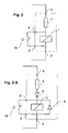
- FIG. 1-A schematically shows an auxiliary device of FIG. opening command operating with a relay with overvoltage 1, commonly called release trigger.
- the auxiliary device comprises two terminals 2 connected to a power supply, at least one pushbutton 10 open in position normal use, and a voltage overvoltage relay 1 that sends a command mechanical opening to a switchgear, not shown, as soon as the voltage applied to its terminals exceeds a predetermined threshold.
- a voltage overvoltage relay 1 that sends a command mechanical opening to a switchgear, not shown, as soon as the voltage applied to its terminals exceeds a predetermined threshold.
- buttons pushers 10 are used, these are mounted in parallel and are all open in position normal use.
- an action on one of the push buttons 10 allows to apply the voltage of the power supply to the terminals of relay 1, which will then control the opening of the switchgear.
- any action on one of the push buttons 10 will be without effect, which poses a security problem. It will be the same in case of cut of the circuit of the push button
- FIG. 1-B shows diagrammatically an auxiliary device of FIG. opening command operating with a relay with undervoltage 1, commonly known as a lack of voltage trigger.
- the auxiliary device comprises two terminals 2 connected to a power supply, at least a push button 10 closed in normal position of use, and a undervoltage relay 1 which sends a opening control to a switchgear, not shown, as soon as the voltage applied to its terminals becomes less than a predetermined threshold.
- the supply voltage is constantly applied to the terminals of relay 1. If a plurality of push buttons 10 is used, these are mounted in series and all closed in the normal position of use, so that an action on one of the push buttons 10 removes the voltage from the power supply at the terminals of relay 1, which will then control the opening of the switchgear.
- the safety problem posed by the emission devices is solved by the Auxiliary devices with undervoltage since the opening command is sent in the event of a power failure or if one of the push buttons 10.
- the auxiliary devices with undervoltage are sensitive to the variations of the network voltage. Indeed, in the case of interruption or voltage drop of the supply related to a mains voltage drop, the auxiliary device will control the opening of the switchgear. This situation is troublesome when the safety must not be opened at each disturbance of the electricity network, and problem of continuity of service.
- instantaneous undervoltage coils are sometimes replaced by delayed undervoltage coils. However, delays are of the order of one second and do not allow to guard against cuts that can last several minutes. In addition, delays that are too long do not allow undervoltage coils to be associated with devices security opening.
- the invention therefore aims to remedy the disadvantages of the state of the art, to provide an auxiliary device for controlling the opening of a switchgear cutting, simple and economical construction, ensuring a good continuity of service while improving safety over over-voltage devices.
- connection terminals short circuit trip means when connected by a link electric.
- the auxiliary device comprises a plurality of impedances now an identical potential across the tripping means when the connection terminals are connected by an electrical connection.
- the auxiliary device comprises a second plurality of terminals power supply to be connected to an external power supply.
- first and second plurality of power terminals are intended to be connected respectively to first and second external power supplies, and includes a plurality of impedances maintaining an identical potential across the means of tripping when the connection terminals are interconnected by a connection electrical and that the two pluralities of power terminals are connected to two external power supplies that work.
- the plurality or pluralities of supply terminals may be optionally to be respectively connected to one or three phase power supplies.
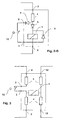
- an auxiliary device for controlling the opening of a switchgear comprises a plurality of power supply terminals 2 intended to be connected to an external power supply, tripping means 1, an impedance 4 and connection terminals 3 intended to be connected to the through one or a plurality of push buttons 10.
- the trigger means 1 are able to send a mechanical control to a switchgear, no shown, as soon as a substantially non-zero voltage is present at their terminals. Only one push button 10 is shown in Figure 2, but the device operates with a any number of push buttons 10 connected in series.
- the electric circuit comprising the triggering means 1, the impedance 4 and the connection terminals 3 and supply 2 delivers to the terminals of tripping means 1 a zero or near zero voltage when the terminals of connection 3 are connected by an electrical connection, and a substantially non-zero voltage when the power terminals 2 are connected to an external power supply which operates and that the electrical connection connecting the connection terminals 3 is interrupted.
- connection terminals 3 are interconnected by one or a plurality of push buttons 10 which are all in the closed position. Current flows then between the connection terminals 3 through the push buttons 10 bypassing the triggering means 1.
- the voltage across the tripping means 1 is zero or very low.
- a momentary drop in the supply circuit voltage will not create a voltage at the terminals of the tripping means 1 which will not be triggered.
- the return to normal the supply circuit voltage also does not require of intervention, the auxiliary device according to the invention returning to its mode of current operation as soon as the power supply connected to terminals 2 regains its voltage nominal.
- the auxiliary device thus ensures an optimal continuity of service.
- the impedance 4 is integrated in the device according to the invention so as to be certain that the current through the device will not be too important.
- the means trigger 1 comprise an electromagnet.
- the electromagnet is de-energized to allow proper operation with low power.
- Optional protection means such as diodes can also be added as shown in FIGS. 2-A or 2-B, to reduce AC consumption, or protect the device in the event of a wiring error.
- the diodes are particularly adapted to a mode of particular embodiment using a de-energizing electromagnet in the means of trigger 1.
- the recovery diode 5 is justified by the polarized nature of the desensitizing electromagnet, and the freewheeling diode 6 improves the operation of the device and taking into account the inductive nature of the electromagnet.
- Figure 2-B is a variant of FIG. 2-A, comprising additional protection means 7 which protect the device in case of bad wiring, especially if the power supply is connected to the connection terminals 3.
- the auxiliary device according to the invention can easily be mounted downstream of the controlled switchgear, while this requires a device additional complex for an undervoltage release as shown in FIG. Figure 1B.
- the undervoltage relay will send a permanent trip order. It is therefore necessary to feed the relay to minimum voltage to make the trigger sequence disappear so that you can re-engage the device. That is why the undervoltage trigger can not be placed downstream of the switchgear unless an additional device is used intended to temporarily supply the relay with undervoltage to be able to re-engage the auxiliary device.
- the auxiliary device according to the invention does not send a permanent trip order if it is not powered. Therefore, a re-engagement is possible without the device is fed beforehand. The auxiliary device can therefore be placed downstream of the switchgear without require the presence of additional temporary feeders.
- FIG. 3 represents another device according to the invention making it possible to use at choice a simple or a double feeding.
- the device of Figure 3 has a first plurality of power supply terminals 2 intended to be connected to a first power supply, and a second plurality of power supply terminals 12 to be connected to a second power supply, and a plurality of impedances 4.
- Terminals 2 and 12 can be connected to a single power supply.
- the system has an operation equivalent to that of the auxiliary device represented in Figure 2, but the operating principle differs slightly in that the pushbuttons 10 do not short circuit the tripping means 1.
- the plurality of impedances 4 is specially chosen so that current operation it maintains an identical potential across the means of tripping 1 when the connection terminals 3 are connected by an electrical connection. Any actuation of the or a push button 10 interrupts the electrical connection between the connection terminals 3 and causes the sending of a mechanical control by the means of trigger 1, a voltage appearing at their terminals because of the imbalance that is created.
- the auxiliary device according to the invention shown in FIG. be connected to two separate power sources. This redundancy of the power supply provides increased security compared to a single-feed mode because it allows to activate the tripping means 1 in the event of a failure on one of the circuits while a single-feed system becomes inoperative in case of failure of the single power supply circuit.
- the two external power supplies 2 and 12 function, the plurality of impedances 4 maintaining an identical potential across tripping means 1 when the connection terminals 3 are connected by a connection electrical, that is to say when the pushbutton or buttons are in the closed position. So, he there is no voltage across the trip means. Actuation of the or of a push button 10 or a failure of any of the power circuits causes a imbalance of potential and shows a voltage across the means of trigger 1, which then fires and sends a command to the switchgear, not shown.
- the auxiliary device according to the invention shown in FIG. to easily switch from a simple power mode to a dual power mode (and conversely), according to the different security options chosen, without changing the device auxiliary.
- FIGS. 2 and 3 show auxiliary devices operating with single-phase power supplies.
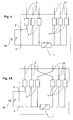
- Figures 4 and 5 show examples of devices auxiliaries according to the invention, operating respectively with a single and a double three-phase power supply.
- the number of power terminals 2 and 12 differs from auxiliary devices shown in Figures 2 and 3, but the principles of operation remain the same.
- FIG. 5-A shows a device according to the invention corresponding to that shown in Figure 3-A, but operating with three-phase power supplies. Both feed lines that are crossed correspond to the same phase.
- relay 1 trips and sends a command signal opening.
Landscapes
- Keying Circuit Devices (AREA)
Abstract
Description
- une pluralité de bornes d'alimentation destinées à être connectées à une première alimentation externe
- des bornes de connexion destinées à être reliées entre elles par au moins un bouton poussoir,
- des moyens de déclenchement aptes à envoyer une commande mécanique, et
- au moins une impédance ;
- les moyens de déclenchement envoyant une commande mécanique vers
l'appareillage de coupure lorsqu'une tension sensiblement non nulle est
présente à leurs bornes, le circuit électrique comportant les moyens de
déclenchement, la ou les impédances et les bornes de connexion et
d'alimentation délivrant aux bornes des moyens de déclenchement :
- une tension nulle ou proche de zéro lorsque les bornes de connexion sont reliées par une liaison électrique,
- une tension sensiblement non nulle lorsque les bornes d'alimentation sont connectées à une alimentation qui fonctionne et que la liaison électrique reliant les bornes de connexion est interrompue.
- la figure 1-A représente un dispositif auxiliaire de l'état de la technique, dit «déclencheur à émission» ;
- la figure 1-B représente un dispositif auxiliaire de l'état de la technique, dit «déclencheur à manque de tension» ;
- les figures 2 représentent un dispositif auxiliaire selon l'invention ;
- les figures 3 représentent un autre dispositif auxiliaire selon l'invention, fonctionnant avec une simple ou une double alimentation ;
- la figure 4 représente un dispositif auxiliaire selon l'invention avec une simple alimentation triphasée ;
- les figures 5 représentent un dispositif auxiliaire selon l'invention avec une double alimentation triphasée.
Claims (6)
- Dispositif auxiliaire de commande d'ouverture destiné à commander l'ouverture d'un appareillage de coupure, comportantcaractérisé en ce queUne pluralité de bornes d'alimentation (2) destinées à être connectées à une première alimentation externe,des bornes de connexion (3) destinées à être reliées entre elles par au moins un bouton poussoir (10),des moyens de déclenchement (1) aptes à envoyer une commande mécanique, etau moins une impédance (4),les moyens de déclenchement (1) envoient une commande mécanique vers l'appareillage de coupure lorsqu'une tension sensiblement non nulle est présente à leurs bornes,le circuit électrique comprenant les moyens de déclenchement (1), la ou les impédances (4) et les bornes de connexion (3) et d'alimentation (2) délivre, aux bornes des moyens de déclenchement (1) :une tension nulle ou proche de zéro lorsque les bornes de connexion (3) sont reliées par une liaison électrique, etune tension sensiblement non nulle lorsque les bornes d'alimentation (2) sont connectées à une alimentation externe qui fonctionne et que la liaison électrique reliant les bornes de connexion (3) est interrompue.
- Dispositif auxiliaire de commande d'ouverture selon la revendication 1, caractérisé en ce que les bornes de connexion (3) court-circuitent les moyens de déclenchement (1) lorsqu'elles sont reliées entre elles par une liaison électrique.
- Dispositif auxiliaire de commande d'ouverture selon la revendication 1, caractérisé en ce qu'il comprend une pluralité d'impédances (4) maintenant un potentiel identique aux deux bornes des moyens de déclenchement (1) lorsque les bornes de connexion (3) sont reliées entre elles par une liaison électrique.
- Dispositif auxiliaire de commande d'ouverture selon la revendication 1, comportant en outre une seconde pluralité de bornes d'alimentation (12) destinées à être connectées à une alimentation externe.
- Dispositif auxiliaire de commande d'ouverture selon la revendication 4, caractérisé en ce que la première et la seconde pluralité de bornes d'alimentation (2, 12) sont destinées à être connectées respectivement à une première et une seconde alimentation distinctes l'une de l'autre, la pluralité d'impédances (4) maintenant un potentiel identique aux bornes des moyens de déclenchement (1) lorsque les bornes de connexion (3) sont reliées entre elles par une liaison électrique et que les deux pluralités de bornes d'alimentation (2, 12) sont connectées à deux alimentations externes qui fonctionnent.
- Dispositif auxiliaire de commande d'ouverture selon l'une quelconque des revendications précédentes, caractérisé en ce que la ou les pluralités de bornes d'alimentation (2, 12) sont destinées à être connectées respectivement à une ou des alimentations triphasées.
Applications Claiming Priority (2)
| Application Number | Priority Date | Filing Date | Title |
|---|---|---|---|
| FR0208308 | 2002-07-03 | ||
| FR0208308A FR2842020B1 (fr) | 2002-07-03 | 2002-07-03 | Dispositif auxiliaire de commande d'ouverture d'un appareillage de coupure |
Publications (2)
| Publication Number | Publication Date |
|---|---|
| EP1378925A1 true EP1378925A1 (fr) | 2004-01-07 |
| EP1378925B1 EP1378925B1 (fr) | 2016-03-30 |
Family
ID=27589628
Family Applications (1)
| Application Number | Title | Priority Date | Filing Date |
|---|---|---|---|
| EP03354048.5A Expired - Lifetime EP1378925B1 (fr) | 2002-07-03 | 2003-06-02 | Dispositif auxiliaire de commande d'ouverture d'un appareillage de coupure |
Country Status (4)
| Country | Link |
|---|---|
| EP (1) | EP1378925B1 (fr) |
| ES (1) | ES2569055T3 (fr) |
| FR (1) | FR2842020B1 (fr) |
| NO (1) | NO324223B1 (fr) |
Citations (2)
| Publication number | Priority date | Publication date | Assignee | Title |
|---|---|---|---|---|
| FR1353016A (fr) * | 1963-01-11 | 1964-02-21 | Forges Ateliers Const Electr | Résistances de shuntage pour dispositifs de sécurité |
| FR2793355A1 (fr) * | 1999-05-06 | 2000-11-10 | Schneider Electric Ind Sa | Dispositif de protection a commande d'ouverture de securite |
-
2002
- 2002-07-03 FR FR0208308A patent/FR2842020B1/fr not_active Expired - Fee Related
-
2003
- 2003-06-02 EP EP03354048.5A patent/EP1378925B1/fr not_active Expired - Lifetime
- 2003-06-02 ES ES03354048.5T patent/ES2569055T3/es not_active Expired - Lifetime
- 2003-06-20 NO NO20032866A patent/NO324223B1/no not_active IP Right Cessation
Patent Citations (2)
| Publication number | Priority date | Publication date | Assignee | Title |
|---|---|---|---|---|
| FR1353016A (fr) * | 1963-01-11 | 1964-02-21 | Forges Ateliers Const Electr | Résistances de shuntage pour dispositifs de sécurité |
| FR2793355A1 (fr) * | 1999-05-06 | 2000-11-10 | Schneider Electric Ind Sa | Dispositif de protection a commande d'ouverture de securite |
Also Published As
| Publication number | Publication date |
|---|---|
| FR2842020A1 (fr) | 2004-01-09 |
| EP1378925B1 (fr) | 2016-03-30 |
| NO324223B1 (no) | 2007-09-10 |
| FR2842020B1 (fr) | 2004-08-13 |
| NO20032866L (no) | 2004-01-05 |
| ES2569055T3 (es) | 2016-05-06 |
| NO20032866D0 (no) | 2003-06-20 |
Similar Documents
| Publication | Publication Date | Title |
|---|---|---|
| EP2053741B1 (fr) | Dispositif de commutation électrique statique auto-protégé | |
| FR3035751A1 (fr) | Coupe-circuit pour courant continu et procede d'utilisation | |
| EP0149372A1 (fr) | Dispositif différentiel résiduel equipe d'un dispositif de surveillance de la source d'alimentation de l'électronique | |
| EP0806781B1 (fr) | Circuit pour l'alimentation protégée d'une charge électrique | |
| EP4167261A1 (fr) | Dispositif de commutation électrique, système de commutation et procédé associés | |
| EP0096601B1 (fr) | Bloc fonctionnel de distribution terminale basse tension | |
| FR3055495A1 (fr) | Procede et dispositif de circuit pour couper une source de tension d'au moins un consommateur | |
| EP3694068B1 (fr) | Système de commutation statique et de limitation d'un courant continu | |
| EP0060790B1 (fr) | Perfectionnements aux disjoncteurs sensibles aux courants de fuite | |
| EP3437115B1 (fr) | Système d'hybridation pour courant continu haute tension | |
| EP3594699B1 (fr) | Dispositif de protection différentielle | |
| EP1378925B1 (fr) | Dispositif auxiliaire de commande d'ouverture d'un appareillage de coupure | |
| EP0130851B1 (fr) | Appareil de protection contre les surtensions pour une installation ou un réseau électrique à basse tension | |
| EP0780861B1 (fr) | Dispositif électrique à communtation d'arc | |
| FR2974662A1 (fr) | Actionneur electromagnetique a generateur magnetique | |
| EP0180506B1 (fr) | Dispositif de sécurité pour appareil de protection différentielle | |
| BE1005336A0 (fr) | Telerupteur a dispositif de limitation de courant. | |
| EP0614259B1 (fr) | Interrupteur différentiel de protection contre les courants de défaut et les surtensions | |
| EP0018867A2 (fr) | Alimentation électrique de sécurité à thyristor | |
| EP4661230A1 (fr) | Circuit de protection d'un système d'alimentation électrique triphasé | |
| EP4016777B1 (fr) | Appareil électrique de protection d'une installation électrique en courant alternatif | |
| EP3627164B1 (fr) | Systeme comprenant un dispositif de commande d'un disjoncteur ultra-rapide d'une installation electrique et procede de test d'un tel systeme | |
| FR2738962A1 (fr) | Dispositif de protection pour derivateurs de surtensions | |
| EP4139946A1 (fr) | Disjoncteur a commande de declenchement electronique | |
| BE488050A (fr) |
Legal Events
| Date | Code | Title | Description |
|---|---|---|---|
| PUAI | Public reference made under article 153(3) epc to a published international application that has entered the european phase |
Free format text: ORIGINAL CODE: 0009012 |
|
| AK | Designated contracting states |
Kind code of ref document: A1 Designated state(s): AT BE BG CH CY CZ DE DK EE ES FI FR GB GR HU IE IT LI LU MC NL PT RO SE SI SK TR |
|
| AX | Request for extension of the european patent |
Extension state: AL LT LV MK |
|
| 17P | Request for examination filed |
Effective date: 20040227 |
|
| AKX | Designation fees paid |
Designated state(s): AT BE BG CH CY CZ DE DK EE ES FI FR GB GR HU IE IT LI LU MC NL PT RO SE SI SK TR |
|
| RAP1 | Party data changed (applicant data changed or rights of an application transferred) |
Owner name: SCHNEIDER ELECTRIC INDUSTRIES SAS |
|
| 17Q | First examination report despatched |
Effective date: 20101223 |
|
| GRAP | Despatch of communication of intention to grant a patent |
Free format text: ORIGINAL CODE: EPIDOSNIGR1 |
|
| RIC1 | Information provided on ipc code assigned before grant |
Ipc: H01H 47/00 20060101ALN20151005BHEP Ipc: H01H 83/20 20060101AFI20151005BHEP |
|
| INTG | Intention to grant announced |
Effective date: 20151021 |
|
| GRAS | Grant fee paid |
Free format text: ORIGINAL CODE: EPIDOSNIGR3 |
|
| GRAA | (expected) grant |
Free format text: ORIGINAL CODE: 0009210 |
|
| AK | Designated contracting states |
Kind code of ref document: B1 Designated state(s): AT BE BG CH CY CZ DE DK EE ES FI FR GB GR HU IE IT LI LU MC NL PT RO SE SI SK TR |
|
| REG | Reference to a national code |
Ref country code: GB Ref legal event code: FG4D Free format text: NOT ENGLISH |
|
| REG | Reference to a national code |
Ref country code: CH Ref legal event code: EP |
|
| REG | Reference to a national code |
Ref country code: AT Ref legal event code: REF Ref document number: 786183 Country of ref document: AT Kind code of ref document: T Effective date: 20160415 |
|
| REG | Reference to a national code |
Ref country code: IE Ref legal event code: FG4D Free format text: LANGUAGE OF EP DOCUMENT: FRENCH |
|
| REG | Reference to a national code |
Ref country code: ES Ref legal event code: FG2A Ref document number: 2569055 Country of ref document: ES Kind code of ref document: T3 Effective date: 20160506 |
|
| REG | Reference to a national code |
Ref country code: DE Ref legal event code: R096 Ref document number: 60348737 Country of ref document: DE |
|
| REG | Reference to a national code |
Ref country code: FR Ref legal event code: PLFP Year of fee payment: 14 |
|
| PG25 | Lapsed in a contracting state [announced via postgrant information from national office to epo] |
Ref country code: FI Free format text: LAPSE BECAUSE OF FAILURE TO SUBMIT A TRANSLATION OF THE DESCRIPTION OR TO PAY THE FEE WITHIN THE PRESCRIBED TIME-LIMIT Effective date: 20160330 Ref country code: GR Free format text: LAPSE BECAUSE OF FAILURE TO SUBMIT A TRANSLATION OF THE DESCRIPTION OR TO PAY THE FEE WITHIN THE PRESCRIBED TIME-LIMIT Effective date: 20160701 |
|
| REG | Reference to a national code |
Ref country code: NL Ref legal event code: MP Effective date: 20160330 |
|
| REG | Reference to a national code |
Ref country code: AT Ref legal event code: MK05 Ref document number: 786183 Country of ref document: AT Kind code of ref document: T Effective date: 20160330 |
|
| PG25 | Lapsed in a contracting state [announced via postgrant information from national office to epo] |
Ref country code: SE Free format text: LAPSE BECAUSE OF FAILURE TO SUBMIT A TRANSLATION OF THE DESCRIPTION OR TO PAY THE FEE WITHIN THE PRESCRIBED TIME-LIMIT Effective date: 20160330 |
|
| PGFP | Annual fee paid to national office [announced via postgrant information from national office to epo] |
Ref country code: BE Payment date: 20160425 Year of fee payment: 14 |
|
| PG25 | Lapsed in a contracting state [announced via postgrant information from national office to epo] |
Ref country code: NL Free format text: LAPSE BECAUSE OF FAILURE TO SUBMIT A TRANSLATION OF THE DESCRIPTION OR TO PAY THE FEE WITHIN THE PRESCRIBED TIME-LIMIT Effective date: 20160330 |
|
| PG25 | Lapsed in a contracting state [announced via postgrant information from national office to epo] |
Ref country code: EE Free format text: LAPSE BECAUSE OF FAILURE TO SUBMIT A TRANSLATION OF THE DESCRIPTION OR TO PAY THE FEE WITHIN THE PRESCRIBED TIME-LIMIT Effective date: 20160330 |
|
| PG25 | Lapsed in a contracting state [announced via postgrant information from national office to epo] |
Ref country code: CZ Free format text: LAPSE BECAUSE OF FAILURE TO SUBMIT A TRANSLATION OF THE DESCRIPTION OR TO PAY THE FEE WITHIN THE PRESCRIBED TIME-LIMIT Effective date: 20160330 Ref country code: SK Free format text: LAPSE BECAUSE OF FAILURE TO SUBMIT A TRANSLATION OF THE DESCRIPTION OR TO PAY THE FEE WITHIN THE PRESCRIBED TIME-LIMIT Effective date: 20160330 Ref country code: RO Free format text: LAPSE BECAUSE OF FAILURE TO SUBMIT A TRANSLATION OF THE DESCRIPTION OR TO PAY THE FEE WITHIN THE PRESCRIBED TIME-LIMIT Effective date: 20160330 Ref country code: AT Free format text: LAPSE BECAUSE OF FAILURE TO SUBMIT A TRANSLATION OF THE DESCRIPTION OR TO PAY THE FEE WITHIN THE PRESCRIBED TIME-LIMIT Effective date: 20160330 Ref country code: PT Free format text: LAPSE BECAUSE OF FAILURE TO SUBMIT A TRANSLATION OF THE DESCRIPTION OR TO PAY THE FEE WITHIN THE PRESCRIBED TIME-LIMIT Effective date: 20160801 |
|
| REG | Reference to a national code |
Ref country code: DE Ref legal event code: R097 Ref document number: 60348737 Country of ref document: DE |
|
| PG25 | Lapsed in a contracting state [announced via postgrant information from national office to epo] |
Ref country code: MC Free format text: LAPSE BECAUSE OF FAILURE TO SUBMIT A TRANSLATION OF THE DESCRIPTION OR TO PAY THE FEE WITHIN THE PRESCRIBED TIME-LIMIT Effective date: 20160330 Ref country code: DK Free format text: LAPSE BECAUSE OF FAILURE TO SUBMIT A TRANSLATION OF THE DESCRIPTION OR TO PAY THE FEE WITHIN THE PRESCRIBED TIME-LIMIT Effective date: 20160330 |
|
| REG | Reference to a national code |
Ref country code: CH Ref legal event code: PL |
|
| PLBE | No opposition filed within time limit |
Free format text: ORIGINAL CODE: 0009261 |
|
| STAA | Information on the status of an ep patent application or granted ep patent |
Free format text: STATUS: NO OPPOSITION FILED WITHIN TIME LIMIT |
|
| 26N | No opposition filed |
Effective date: 20170103 |
|
| REG | Reference to a national code |
Ref country code: IE Ref legal event code: MM4A |
|
| PG25 | Lapsed in a contracting state [announced via postgrant information from national office to epo] |
Ref country code: CH Free format text: LAPSE BECAUSE OF NON-PAYMENT OF DUE FEES Effective date: 20160630 Ref country code: LI Free format text: LAPSE BECAUSE OF NON-PAYMENT OF DUE FEES Effective date: 20160630 |
|
| PG25 | Lapsed in a contracting state [announced via postgrant information from national office to epo] |
Ref country code: IE Free format text: LAPSE BECAUSE OF NON-PAYMENT OF DUE FEES Effective date: 20160602 Ref country code: SI Free format text: LAPSE BECAUSE OF FAILURE TO SUBMIT A TRANSLATION OF THE DESCRIPTION OR TO PAY THE FEE WITHIN THE PRESCRIBED TIME-LIMIT Effective date: 20160330 |
|
| REG | Reference to a national code |
Ref country code: FR Ref legal event code: PLFP Year of fee payment: 15 |
|
| REG | Reference to a national code |
Ref country code: DE Ref legal event code: R084 Ref document number: 60348737 Country of ref document: DE |
|
| PG25 | Lapsed in a contracting state [announced via postgrant information from national office to epo] |
Ref country code: HU Free format text: LAPSE BECAUSE OF FAILURE TO SUBMIT A TRANSLATION OF THE DESCRIPTION OR TO PAY THE FEE WITHIN THE PRESCRIBED TIME-LIMIT; INVALID AB INITIO Effective date: 20030602 Ref country code: CY Free format text: LAPSE BECAUSE OF FAILURE TO SUBMIT A TRANSLATION OF THE DESCRIPTION OR TO PAY THE FEE WITHIN THE PRESCRIBED TIME-LIMIT Effective date: 20160330 |
|
| REG | Reference to a national code |
Ref country code: BE Ref legal event code: MM Effective date: 20170630 |
|
| REG | Reference to a national code |
Ref country code: FR Ref legal event code: PLFP Year of fee payment: 16 |
|
| PG25 | Lapsed in a contracting state [announced via postgrant information from national office to epo] |
Ref country code: TR Free format text: LAPSE BECAUSE OF FAILURE TO SUBMIT A TRANSLATION OF THE DESCRIPTION OR TO PAY THE FEE WITHIN THE PRESCRIBED TIME-LIMIT Effective date: 20160330 Ref country code: LU Free format text: LAPSE BECAUSE OF NON-PAYMENT OF DUE FEES Effective date: 20160602 |
|
| PG25 | Lapsed in a contracting state [announced via postgrant information from national office to epo] |
Ref country code: BG Free format text: LAPSE BECAUSE OF FAILURE TO SUBMIT A TRANSLATION OF THE DESCRIPTION OR TO PAY THE FEE WITHIN THE PRESCRIBED TIME-LIMIT Effective date: 20160330 |
|
| PG25 | Lapsed in a contracting state [announced via postgrant information from national office to epo] |
Ref country code: BE Free format text: LAPSE BECAUSE OF NON-PAYMENT OF DUE FEES Effective date: 20170630 |
|
| PGFP | Annual fee paid to national office [announced via postgrant information from national office to epo] |
Ref country code: GB Payment date: 20210625 Year of fee payment: 19 |
|
| PGFP | Annual fee paid to national office [announced via postgrant information from national office to epo] |
Ref country code: IT Payment date: 20220622 Year of fee payment: 20 |
|
| PGFP | Annual fee paid to national office [announced via postgrant information from national office to epo] |
Ref country code: FR Payment date: 20220623 Year of fee payment: 20 |
|
| PGFP | Annual fee paid to national office [announced via postgrant information from national office to epo] |
Ref country code: ES Payment date: 20220712 Year of fee payment: 20 Ref country code: DE Payment date: 20220628 Year of fee payment: 20 |
|
| GBPC | Gb: european patent ceased through non-payment of renewal fee |
Effective date: 20220602 |
|
| PG25 | Lapsed in a contracting state [announced via postgrant information from national office to epo] |
Ref country code: GB Free format text: LAPSE BECAUSE OF NON-PAYMENT OF DUE FEES Effective date: 20220602 |
|
| REG | Reference to a national code |
Ref country code: DE Ref legal event code: R071 Ref document number: 60348737 Country of ref document: DE |
|
| REG | Reference to a national code |
Ref country code: ES Ref legal event code: FD2A Effective date: 20230628 |
|
| PG25 | Lapsed in a contracting state [announced via postgrant information from national office to epo] |
Ref country code: ES Free format text: LAPSE BECAUSE OF EXPIRATION OF PROTECTION Effective date: 20230603 |