EP1378784A1 - Translucent reflective liquid crystal display - Google Patents
Translucent reflective liquid crystal display Download PDFInfo
- Publication number
- EP1378784A1 EP1378784A1 EP02705319A EP02705319A EP1378784A1 EP 1378784 A1 EP1378784 A1 EP 1378784A1 EP 02705319 A EP02705319 A EP 02705319A EP 02705319 A EP02705319 A EP 02705319A EP 1378784 A1 EP1378784 A1 EP 1378784A1
- Authority
- EP
- European Patent Office
- Prior art keywords
- liquid crystal
- film
- substrate
- optical anisotropic
- anisotropic element
- Prior art date
- Legal status (The legal status is an assumption and is not a legal conclusion. Google has not performed a legal analysis and makes no representation as to the accuracy of the status listed.)
- Withdrawn
Links
Images





Classifications
-
- G—PHYSICS
- G02—OPTICS
- G02F—OPTICAL DEVICES OR ARRANGEMENTS FOR THE CONTROL OF LIGHT BY MODIFICATION OF THE OPTICAL PROPERTIES OF THE MEDIA OF THE ELEMENTS INVOLVED THEREIN; NON-LINEAR OPTICS; FREQUENCY-CHANGING OF LIGHT; OPTICAL LOGIC ELEMENTS; OPTICAL ANALOGUE/DIGITAL CONVERTERS
- G02F1/00—Devices or arrangements for the control of the intensity, colour, phase, polarisation or direction of light arriving from an independent light source, e.g. switching, gating or modulating; Non-linear optics
- G02F1/01—Devices or arrangements for the control of the intensity, colour, phase, polarisation or direction of light arriving from an independent light source, e.g. switching, gating or modulating; Non-linear optics for the control of the intensity, phase, polarisation or colour
- G02F1/13—Devices or arrangements for the control of the intensity, colour, phase, polarisation or direction of light arriving from an independent light source, e.g. switching, gating or modulating; Non-linear optics for the control of the intensity, phase, polarisation or colour based on liquid crystals, e.g. single liquid crystal display cells
- G02F1/133—Constructional arrangements; Operation of liquid crystal cells; Circuit arrangements
- G02F1/1333—Constructional arrangements; Manufacturing methods
- G02F1/1335—Structural association of cells with optical devices, e.g. polarisers or reflectors
- G02F1/13363—Birefringent elements, e.g. for optical compensation
-
- G—PHYSICS
- G02—OPTICS
- G02F—OPTICAL DEVICES OR ARRANGEMENTS FOR THE CONTROL OF LIGHT BY MODIFICATION OF THE OPTICAL PROPERTIES OF THE MEDIA OF THE ELEMENTS INVOLVED THEREIN; NON-LINEAR OPTICS; FREQUENCY-CHANGING OF LIGHT; OPTICAL LOGIC ELEMENTS; OPTICAL ANALOGUE/DIGITAL CONVERTERS
- G02F1/00—Devices or arrangements for the control of the intensity, colour, phase, polarisation or direction of light arriving from an independent light source, e.g. switching, gating or modulating; Non-linear optics
- G02F1/01—Devices or arrangements for the control of the intensity, colour, phase, polarisation or direction of light arriving from an independent light source, e.g. switching, gating or modulating; Non-linear optics for the control of the intensity, phase, polarisation or colour
- G02F1/13—Devices or arrangements for the control of the intensity, colour, phase, polarisation or direction of light arriving from an independent light source, e.g. switching, gating or modulating; Non-linear optics for the control of the intensity, phase, polarisation or colour based on liquid crystals, e.g. single liquid crystal display cells
- G02F1/133—Constructional arrangements; Operation of liquid crystal cells; Circuit arrangements
- G02F1/1333—Constructional arrangements; Manufacturing methods
- G02F1/1335—Structural association of cells with optical devices, e.g. polarisers or reflectors
-
- G—PHYSICS
- G02—OPTICS
- G02F—OPTICAL DEVICES OR ARRANGEMENTS FOR THE CONTROL OF LIGHT BY MODIFICATION OF THE OPTICAL PROPERTIES OF THE MEDIA OF THE ELEMENTS INVOLVED THEREIN; NON-LINEAR OPTICS; FREQUENCY-CHANGING OF LIGHT; OPTICAL LOGIC ELEMENTS; OPTICAL ANALOGUE/DIGITAL CONVERTERS
- G02F1/00—Devices or arrangements for the control of the intensity, colour, phase, polarisation or direction of light arriving from an independent light source, e.g. switching, gating or modulating; Non-linear optics
- G02F1/01—Devices or arrangements for the control of the intensity, colour, phase, polarisation or direction of light arriving from an independent light source, e.g. switching, gating or modulating; Non-linear optics for the control of the intensity, phase, polarisation or colour
- G02F1/13—Devices or arrangements for the control of the intensity, colour, phase, polarisation or direction of light arriving from an independent light source, e.g. switching, gating or modulating; Non-linear optics for the control of the intensity, phase, polarisation or colour based on liquid crystals, e.g. single liquid crystal display cells
- G02F1/133—Constructional arrangements; Operation of liquid crystal cells; Circuit arrangements
- G02F1/1333—Constructional arrangements; Manufacturing methods
- G02F1/1335—Structural association of cells with optical devices, e.g. polarisers or reflectors
- G02F1/133553—Reflecting elements
- G02F1/133555—Transflectors
-
- G—PHYSICS
- G02—OPTICS
- G02F—OPTICAL DEVICES OR ARRANGEMENTS FOR THE CONTROL OF LIGHT BY MODIFICATION OF THE OPTICAL PROPERTIES OF THE MEDIA OF THE ELEMENTS INVOLVED THEREIN; NON-LINEAR OPTICS; FREQUENCY-CHANGING OF LIGHT; OPTICAL LOGIC ELEMENTS; OPTICAL ANALOGUE/DIGITAL CONVERTERS
- G02F1/00—Devices or arrangements for the control of the intensity, colour, phase, polarisation or direction of light arriving from an independent light source, e.g. switching, gating or modulating; Non-linear optics
- G02F1/01—Devices or arrangements for the control of the intensity, colour, phase, polarisation or direction of light arriving from an independent light source, e.g. switching, gating or modulating; Non-linear optics for the control of the intensity, phase, polarisation or colour
- G02F1/13—Devices or arrangements for the control of the intensity, colour, phase, polarisation or direction of light arriving from an independent light source, e.g. switching, gating or modulating; Non-linear optics for the control of the intensity, phase, polarisation or colour based on liquid crystals, e.g. single liquid crystal display cells
- G02F1/133—Constructional arrangements; Operation of liquid crystal cells; Circuit arrangements
- G02F1/1333—Constructional arrangements; Manufacturing methods
- G02F1/1335—Structural association of cells with optical devices, e.g. polarisers or reflectors
- G02F1/13363—Birefringent elements, e.g. for optical compensation
- G02F1/133632—Birefringent elements, e.g. for optical compensation with refractive index ellipsoid inclined relative to the LC-layer surface
-
- G—PHYSICS
- G02—OPTICS
- G02F—OPTICAL DEVICES OR ARRANGEMENTS FOR THE CONTROL OF LIGHT BY MODIFICATION OF THE OPTICAL PROPERTIES OF THE MEDIA OF THE ELEMENTS INVOLVED THEREIN; NON-LINEAR OPTICS; FREQUENCY-CHANGING OF LIGHT; OPTICAL LOGIC ELEMENTS; OPTICAL ANALOGUE/DIGITAL CONVERTERS
- G02F1/00—Devices or arrangements for the control of the intensity, colour, phase, polarisation or direction of light arriving from an independent light source, e.g. switching, gating or modulating; Non-linear optics
- G02F1/01—Devices or arrangements for the control of the intensity, colour, phase, polarisation or direction of light arriving from an independent light source, e.g. switching, gating or modulating; Non-linear optics for the control of the intensity, phase, polarisation or colour
- G02F1/13—Devices or arrangements for the control of the intensity, colour, phase, polarisation or direction of light arriving from an independent light source, e.g. switching, gating or modulating; Non-linear optics for the control of the intensity, phase, polarisation or colour based on liquid crystals, e.g. single liquid crystal display cells
- G02F1/133—Constructional arrangements; Operation of liquid crystal cells; Circuit arrangements
- G02F1/1333—Constructional arrangements; Manufacturing methods
- G02F1/1335—Structural association of cells with optical devices, e.g. polarisers or reflectors
- G02F1/13363—Birefringent elements, e.g. for optical compensation
- G02F1/133633—Birefringent elements, e.g. for optical compensation using mesogenic materials
-
- G—PHYSICS
- G02—OPTICS
- G02F—OPTICAL DEVICES OR ARRANGEMENTS FOR THE CONTROL OF LIGHT BY MODIFICATION OF THE OPTICAL PROPERTIES OF THE MEDIA OF THE ELEMENTS INVOLVED THEREIN; NON-LINEAR OPTICS; FREQUENCY-CHANGING OF LIGHT; OPTICAL LOGIC ELEMENTS; OPTICAL ANALOGUE/DIGITAL CONVERTERS
- G02F1/00—Devices or arrangements for the control of the intensity, colour, phase, polarisation or direction of light arriving from an independent light source, e.g. switching, gating or modulating; Non-linear optics
- G02F1/01—Devices or arrangements for the control of the intensity, colour, phase, polarisation or direction of light arriving from an independent light source, e.g. switching, gating or modulating; Non-linear optics for the control of the intensity, phase, polarisation or colour
- G02F1/13—Devices or arrangements for the control of the intensity, colour, phase, polarisation or direction of light arriving from an independent light source, e.g. switching, gating or modulating; Non-linear optics for the control of the intensity, phase, polarisation or colour based on liquid crystals, e.g. single liquid crystal display cells
- G02F1/137—Devices or arrangements for the control of the intensity, colour, phase, polarisation or direction of light arriving from an independent light source, e.g. switching, gating or modulating; Non-linear optics for the control of the intensity, phase, polarisation or colour based on liquid crystals, e.g. single liquid crystal display cells characterised by the electro-optical or magneto-optical effect, e.g. field-induced phase transition, orientation effect, guest-host interaction or dynamic scattering
- G02F1/139—Devices or arrangements for the control of the intensity, colour, phase, polarisation or direction of light arriving from an independent light source, e.g. switching, gating or modulating; Non-linear optics for the control of the intensity, phase, polarisation or colour based on liquid crystals, e.g. single liquid crystal display cells characterised by the electro-optical or magneto-optical effect, e.g. field-induced phase transition, orientation effect, guest-host interaction or dynamic scattering based on orientation effects in which the liquid crystal remains transparent
- G02F1/1393—Devices or arrangements for the control of the intensity, colour, phase, polarisation or direction of light arriving from an independent light source, e.g. switching, gating or modulating; Non-linear optics for the control of the intensity, phase, polarisation or colour based on liquid crystals, e.g. single liquid crystal display cells characterised by the electro-optical or magneto-optical effect, e.g. field-induced phase transition, orientation effect, guest-host interaction or dynamic scattering based on orientation effects in which the liquid crystal remains transparent the birefringence of the liquid crystal being electrically controlled, e.g. ECB-, DAP-, HAN-, PI-LC cells
-
- G—PHYSICS
- G02—OPTICS
- G02F—OPTICAL DEVICES OR ARRANGEMENTS FOR THE CONTROL OF LIGHT BY MODIFICATION OF THE OPTICAL PROPERTIES OF THE MEDIA OF THE ELEMENTS INVOLVED THEREIN; NON-LINEAR OPTICS; FREQUENCY-CHANGING OF LIGHT; OPTICAL LOGIC ELEMENTS; OPTICAL ANALOGUE/DIGITAL CONVERTERS
- G02F2413/00—Indexing scheme related to G02F1/13363, i.e. to birefringent elements, e.g. for optical compensation, characterised by the number, position, orientation or value of the compensation plates
- G02F2413/04—Number of plates greater than or equal to 4
-
- G—PHYSICS
- G02—OPTICS
- G02F—OPTICAL DEVICES OR ARRANGEMENTS FOR THE CONTROL OF LIGHT BY MODIFICATION OF THE OPTICAL PROPERTIES OF THE MEDIA OF THE ELEMENTS INVOLVED THEREIN; NON-LINEAR OPTICS; FREQUENCY-CHANGING OF LIGHT; OPTICAL LOGIC ELEMENTS; OPTICAL ANALOGUE/DIGITAL CONVERTERS
- G02F2413/00—Indexing scheme related to G02F1/13363, i.e. to birefringent elements, e.g. for optical compensation, characterised by the number, position, orientation or value of the compensation plates
- G02F2413/08—Indexing scheme related to G02F1/13363, i.e. to birefringent elements, e.g. for optical compensation, characterised by the number, position, orientation or value of the compensation plates with a particular optical axis orientation
-
- G—PHYSICS
- G02—OPTICS
- G02F—OPTICAL DEVICES OR ARRANGEMENTS FOR THE CONTROL OF LIGHT BY MODIFICATION OF THE OPTICAL PROPERTIES OF THE MEDIA OF THE ELEMENTS INVOLVED THEREIN; NON-LINEAR OPTICS; FREQUENCY-CHANGING OF LIGHT; OPTICAL LOGIC ELEMENTS; OPTICAL ANALOGUE/DIGITAL CONVERTERS
- G02F2413/00—Indexing scheme related to G02F1/13363, i.e. to birefringent elements, e.g. for optical compensation, characterised by the number, position, orientation or value of the compensation plates
- G02F2413/10—Indexing scheme related to G02F1/13363, i.e. to birefringent elements, e.g. for optical compensation, characterised by the number, position, orientation or value of the compensation plates with refractive index ellipsoid inclined, or tilted, relative to the LC-layer surface O plate
- G02F2413/105—Indexing scheme related to G02F1/13363, i.e. to birefringent elements, e.g. for optical compensation, characterised by the number, position, orientation or value of the compensation plates with refractive index ellipsoid inclined, or tilted, relative to the LC-layer surface O plate with varying inclination in thickness direction, e.g. hybrid oriented discotic LC
Definitions
- the present invention relates to a liquid crystal display provided with both reflection and transmission functions which display is used in various office automation (OA) equipment such as a word processor and a personal computer, mobile information terminals such as a mobile telephone device and a PDA (Personal Digital Assistant), or camcorders equipped with a liquid crystal monitor.
- OA office automation
- PDA Personal Digital Assistant
- a liquid crystal display has been increasingly expected to expand its market to that of a display for portable information terminal devices where the liquid crystal display can make the best use of its peculiar characteristics, i.e., thin in size and light in weight.
- Displaying modes used in a reflection type liquid crystal display are those widely used in a transmission type such as TN(twisted nematic) and STN(super twisted nematic) modes.
- TN and STN modes do not have sufficient display qualities as currently demanded in terms of luminance and contrast and are required to be improved in display qualities such as high luminance and improved contrast.
- the reflection type liquid crystal display has a drawback that it is extremely deteriorated in visibility when it is used in a dark place, resulting in the decrease in the reflection light to be used for displaying.
- the transmission type liquid crystal display contrary to this, has a problem that it is deteriorated in visibility when used under bright circumstances such as fine weather.
- a transflective liquid crystal display which combines a transmission display mode and a reflection display mode.
- it has a problem that light leakage occurs in a black display state, resulting in insufficient black level.
- the transflective liquid crystal display needs to make an incident of light to the liquid crystal layer through a region with a transmission function in the transmission mode. Therefore, it is necessary to dispose a polarizer and one or more polymeric stretched films typically polycarbonates between the liquid crystal layer and the back light.
- the liquid crystal display in the transmission mode can not essentiallyavoidproblemsregardingviewingangle that the refractive index anisotropy peculiar to the liquid crystal molecules changes the displaying color and reduces the displaying contrast, when viewing the display from an oblique direction, and it is essentially difficult for such a combination of polymeric stretched films and a polarizer to enlarge the viewing angle.
- the object of the present invention is to provide a transflective liquid crystal display which is bright in the transmission mode, high in contrast, and less dependent on the viewing angle.
- a transflectiveliquid crystal display which comprises a first substrate having a transparent electrode, a second substrate having a transflective electrode on which a region having a reflection function is formed and a region having a transmission function is formed, a homogeneously oriented liquid crystal layer sandwiched between the first and second substrates, a first optical anisotropic element arranged on the surface of the first substrate opposite to the surface contacting the liquid crystal layer, a polarizer arranged on the first optical anisotropic element, a second optical anisotropic element arranged on the surface opposite to the surface of the second substrate contacting the liquid crystal layer, and a polarizer arranged on the lower surface of the second optical anisotropic element wherein the second optical anisotropic element comprises at least one sheet of liquid crystal film obtained by fixing a nematic hybrid orientation formed by a liquid crystalline polymer exhibiting an optically positive uniaxial property, in a liquid crystal state.
- the transflective liquid crystal display of the first aspect wherein the second optical anisotropic element comprises at least one sheet of liquid crystal film obtained by fixing a nematic hybrid orientation formed by a liquid crystalline polymer exhibiting an optically positive uniaxial property, in a liquid crystal state and at least one sheet of polymeric stretched film.
- the transflective liquid crystal display of the first or second aspect wherein an angle is within the range of 0 to 30 degrees which angle is formed by a tilt direction of the liquid crystal film defined by the projection direction of the director of the liquid crystalline polymer molecule on the upper or lower surface of the liquid crystal film to whichever an angle of the director of the liquid crystalline polymer is smaller and a pretilt direction defined by the projection direction of the director of the liquid crystalline molecule on the cell interface on the first substrate side.
- the transflective liquid crystal display of either one of the first to third aspects wherein the liquid crystal layer has a smaller thickness at the region having a reflection function than at the region having a transmission function.
- the transflective liquid crystal display of the present invention comprises a first substrate having a transparent electrode, a second substrate having a transflective electrode on which a region having a reflection function is formed and a region having a transmission function is formed, a homogeneously oriented liquid crystal layer sandwiched between the first and second substrates, a first optical anisotropic element arranged on the surface of the first substrate opposite to the surface contacting the liquid crystal layer, a polarizerarrangedonthefirstopticalanisotropic element, a second optical anisotropic element arranged on the surface opposite to the surface of the second substrate contacting the liquid crystal layer, and a polarizer arranged on the lower surface of the second optical anisotropic element wherein the second optical anisotropic element comprises at least one sheet of liquid crystal film obtained by fixing a nematic hybrid orientation formed by a liquid crystalline polymer exhibiting an optically positive uniaxial property, in a liquid crystal state
- the transflective liquid crystal display of the present invention is characterized in that the second optical anisotropic element comprises at least one sheet of liquid crystal film obtained by fixing a nematic hybrid orientation formed by a liquid crystalline polymer exhibiting an optically positive uniaxial property, in a liquid crystal state.
- the transflective liquid crystal display of the present invention is constructed by a polarizer, a first optical anisotropic element, a first substrate having a transparent electrode, an oriented liquid crystal layer, a second substrate having a transflective electrode (hereinafter referred to as "reflection layer" if necessary) on which a region having a reflection function is formed and a region having a transmission function is formed, a second optically anisotropic element, a polarizer, and a back light, in the order as mentioned.
- additional components such as a photo diffusing layer, a light-controlled film, a light guide plate, a prism sheet or the like may be provided.
- the transflective liquid crystal display of the present invention can be used both in a reflection mode and in a transmission mode by arranging a back light in the rear.
- liquid crystal cell constituted by the first substrate, the second substrate, and the homogeneously oriented liquid crystal layer sandwiched therebetween used in the present invention.
- the liquid crystal cell contains the second substrate having a transflective electrode on which a region having a reflection function is formed and a region having a transmission function is formed.
- the region having a reflection function will be a reflection display part, while the region having a transmission function will be a transmission display part.
- the liquid crystal layer has a smaller thickness at the region having a reflection function than at the region having a transmission function. The reason of this is set forth below.
- the degree of change in the state of polarized light involved with the change in the liquid crystal layer orientation by an external field such as an electric field in the case where the liquid crystal layer thickness is made to be suitable for reflection displaying is an extent that a light made incident from the observer side through the liquid crystal layer is reflected at the reflection layer and exits through the liquid crystal layer again to the observer side thereby obtaining a sufficient contrast ratio.
- the degree of change in the orientation state of a light passing through the liquid crystal layer is insufficient in the transmission display part.
- the transmission display part would lack luminance or would have a sufficient luminance but not be reduced in the transmittance upon a dark display, leading to a poor contrast ratio.
- the liquid crystal orientation state in the liquid crystal layer is controlled by an applied voltage such that an optical retardation with about 1/4 wavelength is imparted to a light passing through the liquid crystal layer only once.
- Transmission displaying effected with a liquid crystal layer with a thickness suitable for reflection displaying, i.e., by effecting a voltage modulation providing a phase modulation of a 1/4 wavelength can not obtain a sufficiently bright display because the sufficient reduction of the transmittance when the transmittance display part is in a dark display mode causes the absorption of almost half of luminous intensity of light by the polarizer arranged on the side to which the light is reflected.
- the luminosity upon a dark display mode of the transmission display part will be about 1/2 of that upon the bright display mode, leading to a poor contrast ratio.
- the liquid crystal layer of the reflection display part in order to make the thickness of the liquid crystal layer suitable for transmission displaying, a voltage modulation must be applied to the liquid crystal layer such that an optical retardation of a 1/2 wavelength is imparted to a light transmitting the liquid crystal layer. Therefore, in order to utilize both a reflected light and a transmitting light for a display mode with high resolution and excellent visibility, the liquid crystal layer of the reflection display part must be thicker than that of the transmission display part.
- the liquid crystal layer thickness of the reflection display part is preferably from 30 to 90 percent and particularly preferably from 40 to 60 percent of that of the transmission display part. Ideally, the liquid crystal layer thickness of the reflection display part is about 1/2 of that of the transmission display part.
- the mode of the liquid crystal cell is preferably a display mode utilizing an electrically controlled birefringence (ECB) in which liquid crystalline molecules are homogeneously oriented.
- EBC electrically controlled birefringence
- the use of a TN or STN mode is not preferred because a problem from the viewpoint of production is susceptible to happen due to a defect in the liquid crystalline molecule orientation arising at the boundary between the transmission display part and the reflection display part when the difference in thickness therebetween becomes larger.
- the driving mode of the liquid crystal cell may be a passive matrix mode used in an STN-LCD, an active matrix mode using active electrodes such as TFT (Thin Film Transistor) electrodes and TFD (Thin Film Diode) electrodes, and a plasma address mode.
- TFT Thin Film Transistor
- TFD Thin Film Diode
- the first substrate used in the present invention is a transparent substrate having a transparent electrode (counter electrode) while the second substrate is a transparent substrate having a transflective electrode.
- the transparent substrate forming the first or second substrate aligns a material exhibiting a liquid crystallinity forming the liquid crystal layer in a specific orientation direction.
- a transparent substrate having properties to align liquid crystal there may be used either a transparent substrate having properties to align liquid crystal or a transparent substrate having no such properties but provided with an alignment film or the like having such properties.
- Electrodes for the cell may be conventional ones such as an ITO.
- the electrode can be provided on the surface contacting the liquid crystal layer, of the transparent substrate.
- the electrode may be provided between the substrate and the alignment film.
- liquid crystalline material forming the liquid crystal layer No particular limitation is imposed on the liquid crystalline material forming the liquid crystal layer. Therefore, there may be used conventional various low molecular weight- and polymeric-liquid crystalline substances and mixtures thereof.
- the liquid crystalline material may be blended with a dye, a chiral dopant, and a non-liquid crystalline substance to an extent that the liquid crystallinity is not adversely affected.
- the reflection layer material may be a metal such as aluminum, silver, gold, chromium, and platinum, an alloy containing one or more of these metals, an oxide such as magnesium oxide, a laminate of films of dielectrics, a liquid crystal film exhibiting a selective reflectivity, and combinations thereof.
- These reflection layers may be flat or curved and may be those provided with diffusive reflectivity by forming rugged patterns on its surface, those having a function as the electrode on the electrode substrate located on the side opposite to the viewing side, or any combination thereof.
- PVA-based polarizing films such as polyvinyl alcohol (PVA) and partial acetal PVA
- polarizing films such as those obtained by stretching a hydrophilic polymeric film comprising a partially saponified product of an ehtylene-vinyl acetate copolymer and absorbing iodine and/or dichroic dye
- polarizing films such as those obtained by stretching a hydrophilic polymeric film comprising a partially saponified product of an ehtylene-vinyl acetate copolymer and absorbing iodine and/or dichroic dye
- a polyene-oriented film such as a dehydrated product of PVA and a dechlorinated product of polyvinyl chloride.
- reflection type polarizers there may be used.
- polarizers may be used independently or in combination with a transparent protective layer provided on one or both surfaces of the polarizer for the purpose of enhancing the strength, moisture resistance, and heat resistance.
- a transparent protective layer are those formed by laminating a transparent plastic film such as polyester and triacetyl cellulose directly or via an adhesive layer on the polarizer; coated layers of resin; and acrylic- or epoxy-based photo-setting type resin layers.
- the protective layers When the protective layers are coated on both surfaces of the polarizing film, they may be the same or different.
- the first optical retardation element used in the present invention has excellent transparency and uniformity.
- polymeric stretched films are uniaxial or biaxial optical retardation films formed with cellulose-, polycarbonate-, polyallylate-, polysulfone-, polyacryl, polyethersulfone-, or cyclic olefin-based polymers.
- polycarbonate-based polymers are preferred in terms of cost and film uniformity.
- a film with less birefringence chromatic dispersivity such as "ARTON" manufactured by JSR Corporation is also preferred because it can suppress the color modulation in the picture quality.
- optical compensation film formed from a liquid crystal material examples are those comprised of various liquid crystalline polymeric compounds exhibiting a main chain- and/or side chain-type liquid crystallinity such as liquid crystalline polyester, liquid crystalline polycarbonate, liquid crystalline polyacrylate, orliquidcrystallinepolymalonateorlowmolecular weight liquid crystalline substances having reactivities which can be polymerized by cross-linking or the like after being oriented.
- These films may be a single-layered film with self-supportiveness or formed over a transparent supporting substrate.
- One or more of the first optical retardation elements may be used in the present invention.
- a polymeric stretched film and a liquid crystal optical compensation film may be used in combination.
- the second optical anisotropic element used in the present invention comprises at least one sheet of liquid crystal film obtained by fixing a nematic hybrid orientation formed by a liquid crystalline polymer exhibiting an optically positive uniaxial property, in a liquid crystal state.
- the second optical anisotropic element preferably comprises at least one sheet of liquid crystal film obtained by fixing a nematic hybrid orientation formed by a liquid crystalline polymer exhibitinganopticallypositiveuniaxialproperty, in a liquid crystal state and at least one sheet of polymeric stretched film.
- the second optical anisotropic element used in the present invention comprises a liquid crystalline polymer exhibiting an optically positive uniaxial property, more specifically a liquid crystalline polymeric compound exhibiting an optically positive uniaxial property or a liquid crystalline polymeric composition comprising at least one kind of liquid crystalline compound and exhibitinganopticallypositiveuniaxialproperty and contains at least a liquid crystal film wherein a nematic hybrid orientation formed by the liquid crystalline polymeric compound or composition under a liquid crystal state is fixed.
- nematic hybrid orientation used herein denotes an orientation structure wherein the liquid crystalline molecules are oriented in a nematic phase wherein the director of a liquid crystalline polymer to the upper and lower surfaces of the film form angles (tilt angles) different from each other in the respective surface. Therefore, since the angles formed by the director and the film planes are different between in the vicinities of the upper and lower interface of the film, the nematic hybrid orientation can be defined by an orientation wherein the tilt angle varies continuously between the upper and lower film surfaces.
- the average tilt angle in the nematic hybrid orientation structure is preferably within the range of 5 to 45 degrees.
- the liquid crystal film is one with a fixed nematic hybrid orientation structure in which the directors of the liquid crystalline molecules are directed at different angles in all the positions in the film thickness direction as described above. Therefore, there no longer exists optical axis in the whole film structure.
- the term "average tilt angle" used herein denotes the average value of the angles between the directors of the liquid crystalline molecules and a film plane along the liquid crystal film thickness direction.
- the absolute value of the angle formed by the directors of the liquid crystalline molecules in the vicinity of one film interface and the film surface is generally 20 to 90 degrees, preferably 30 to 70 degrees, while the absolute value of the angle in the vicinity of the opposing film interface is generally 0 to 20 degrees, preferably 0 to 10 degrees.
- the absolute value of the average tilt angle in the orientation structure is generally 5 to 45 degrees, preferably 7 to 40 degrees, more preferably 10 to 38 degrees, and most preferably 15 to 35 degrees.
- the average tilt angle if deviating from the above range, would cause the decrease of contrast of the resulting liquid crystal display.
- the average tilt angle can be determined by applying a crystal rotation method.
- the liquid crystal film forming the second optical anisotropic element may be formed of any liquid crystalline material as long as the film has a fixed nematic hybrid orientation structure and a specific average tilt angle.
- the film may be one obtained by aligning a low molecular weight liquid crystalline substance in a liquid crystalline state so as to assume a nematic hybrid orientation and fixing the orientation structure by photo- or thermal- crosslinking or one obtained by aligning a polymeric liquid crystallinesubstanceinaliquidcrystallinestate so as to assume a nematic hybrid orientation and fixing the orientation structure by cooling.
- the term "liquid crystal film” used herein may denotes one obtained by forming a low molecular weight or polymeric liquid crystalline substance into a film and thus the liquid crystal film itself may not have a liquid crystallinity.
- the thickness of the liquid crystal film which can exhibit a suitable viewing angle improving effectforthetransflectiveliquidcrystaldisplay can not be determined with certainty because it depends on the mode and various optical parameters of the liquid crystal display wherein the film is provided.
- the thickness is generally from 0.2 ⁇ m to 10 ⁇ m, preferably from 0.3 ⁇ m to 5 ⁇ m, and more preferably 0, 5 ⁇ m to 2 ⁇ m.
- the thickness of less than 0.2 ⁇ m would possibly fail to obtain a compensation effect.
- the thickness of more than 10 ⁇ m would probably cause the resulting liquid crystal display to be colored undesirously.
- a pseudo retardation value in the plane of a liquid crystal film plane when viewing the film from the normal direction is explained as follows. That is, in a liquid crystal film with a fixed nematic hybrid orientation structure, the refractive index (n e ) parallel to the directors is different from the refractive index (n o ) perpendicular to the directors. Therefore, the value obtained by subtracting n o from n e is defined as a pseudo birefringence, and the pseudo retardation value is determined by the product of the birefringence and the absolute film thickness. Generally, this pseudo retardation value is easily obtainedbyapolarizationopticalmeasurementsuch as ellipsometry.
- the pseudo retardation value of the liquid crystal film used as the optical anisotropic element is within the range of generally 10 nm to 600 nm, preferably 30 nm to 400 nm, and more preferably 50 nm to 300 nm with respect to a single color light of 550 nm.
- a retardation value of less than 10 nm would possibly fail to enlarge the viewing angle of the resulting liquid crystal display.
- a retardation value of more than 600 nm would cause unnecessary coloration in the resulting liquid crystal display when viewing the display obliquely.
- the arrangement conditions of the optical anisotropic elements in the transflective liquid crystal display of the present invention will be described in more detail.
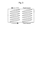
- the upper and lower planes of the optical anisotropic element comprised of the liquid crystal film, the tilt direction of the element and the pretilt direction of the liquid crystal cell are defined using Figs. 2 and 3 below, respectively.
- the plane forming an angle of 20 to 90 degrees at the acute angle side with the director is defined as "b-plane" while the plane forming an angle of 0 to 20 degrees at the acute angle side is defined as "c-plane”.
- the tilt direction of the optical anisotropic element is defined by a direction in which when viewing through the liquid crystal film from the b-plane side to the c-plane side, the director of a liquid crystalline molecule and the projection thereof on the c-plane forms an acute angle and which is parallel to the projection (Figs. 1 and 2) .
- a driving low molecular weight liquid crystal is not parallel to the cell interface and tilted at a certain angle which is generally referred to as "pre-tilt angle".
- pre-tilt angle a direction along which the director of a liquid crystalline molecule on the cell interface and the projection thereof form an acute angle and which is parallel to the projection.
- the second optical anisotropic element may be comprised of the above-described liquid crystal film and a polymeric stretched film.
- polymeric stretched film examples include mediums exhibiting uni- or bi-axial properties which may be various polymeric stretched films such as polycarbonate (PC), polymethacrylate (PMMA), polyvinyl alcohol (PVA) , and "ARTON” manufactured by JSR Corporation.
- PC polycarbonate
- PMMA polymethacrylate
- PVA polyvinyl alcohol
- ARTON ARTON manufactured by JSR Corporation.
- the combination of a single liquid crystal film and a single polymeric stretched film is practically preferred in view of the production cost.
- the liquid crystal film of the second anisotropic element may be used as a single unit or in combination with a supporting substrate such as a transparent plastic film.
- the liquid crystal film may be used integrally with a polarizer.
- the liquid crystal film and/or a polymeric stretched film may be integrated with a polarizer via a pressure-sensitive adhesive or an adhesive.
- the film is preferably arranged between the second substrate of the liquid crystal cell and the polarizer. It is also preferred that the tilt direction of the liquid crystal film is roughly coincide with the pretilt direction of the liquid crystalline molecule of the liquid crystal layer on the liquid crystal interface facing the first substrate.
- the absolute value of the angle formed by the tilt direction and the pretilt direction is within the range of preferably 0 to 30 degrees, more preferably 0 to 20 degrees, and particularly preferably 0 to 10 degrees. The angle in excess of 30 degrees would result in a poor viewing angle compensation effect.
- the combination of a single liquid crystal film and a single polymeric stretched film is used as the second optical anisotropic element for the transflective liquid crystal display, they are arranged between the second substrate and the polarizer.
- the liquid crystal film may be arranged on the side adjacent to the liquid crystal cell or the side adjacent to the polarizer.
- the liquid crystal film when the liquid crystal film and a polymeric stretched film are arranged, the liquid crystal film is preferably arranged similarly to the case where only a single liquid crystal film is used. That is, it is preferred that the tilt direction of the liquid crystalline polymer in the liquid crystal film is roughly coincide with the pretilt direction of the liquid crystalline molecule of the liquid crystal layer on the liquid crystal interface facing the first substrate.
- the angle formed by the tilt direction and the pretilt direction is within the range of preferably 0 to 30 degrees, more preferably 0 to 20 degrees, and particularly preferably 0 to 10 degrees.
- the polymeric stretched film is arranged such that the tilt direction of the liquid crystal film and the retardation axis of the polymeric stretched film form an angle within the range of preferably 40 to 80 degrees and more preferably 50 to 70 degrees.
- the transflective liquid crystal display of the present invention may be provided with another additional components.
- the use of a color filter makes it possible to produce a color liquid crystal display which can provide multi-or full- colored images with increased color purity.
- the transflective liquid crystal display of the present invention can provide a bright image of high contrast in the transmission mode and excellent viewing angle properties.
- the present invention will be further described with reference to the following inventive and comparative examples but is not limited thereto.
- the retardations ( ⁇ nd) in the examples are values at a wavelength of 550 nm, unless stated otherwise.
- Fig. 5 shows schematically the transflective liquid crystal display used in Example 1.
- the transflective electrode 6 constituted by a reflective electrode of a highly reflective material such as Al and a highly transmissive materials such ITO, while on the transparent substrate 3 was disposed the counter electrode 4.
- the liquid crystal layer 5 formed of a liquid crystalline material exhibiting a positive dielectric constant anisotropy was sandwiched between the transflective electrode 6 and the counter electrode 4.
- the first optical anisotropic element 2 and a polarizer 1 are arranged on the surface opposite to the counter electrode of the transparent substrate 3 and the second optical anisotropic element 8 and the polarizer 9 are arranged on the surface opposite to the transflective electrode 6 of the substrate 7.
- the back light 10 is also provided on the rear side of the polarizer 9.
- a liquid crystal film 16 with a thickness of 0.68 ⁇ m was produced in which film a nematic hybrid orientation wherein the average tilt angle in the thickness direction was 28 degrees is fixed, thereby producing an ECB-type transflective liquid crystal display with the components arrangement shown in Fig. 5.
- the liquid crystal cell 13 used herein contained ZLI-1695 manufactured by Merck Ltd. as a liquid crystalline material.
- the resulting liquid crystal layer 5 had a reflective electrode region (reflection display part) with a thickness of 2.4 ⁇ m and a transmission electrode region (transmission display part) with a thickness of 4.8 ⁇ m.
- the pretilt angles of the liquid crystal layer on the both interfaces of the substrates were 2 degrees, respectively, the ⁇ nd of the liquid crystal cell was approximately 150 nm and 300 nm in the reflection display part and the transmission display part, respectively.
- the polarizer 1 with a thickness of 180 ⁇ m (SQW-862 manufactured by Sumitomo Chemical Industry Co., Ltd.) was arranged on the viewing side (upper portion in the drawing) of the liquid crystal cell 13, and therebetween was arranged the first optical anisotropic element 2 constituted by polymeric stretched films 14 and 15 each formed by a uniaxially stretched polycarbonate film.
- the ⁇ nd of the polymeric stretched film 14 was approximately 268 nm, while the ⁇ nd of the polymeric stretched film 15 was approximately 98 nm.
- the second anisotropic element 8 constituted by the liquid crystal film 16 and the polymeric stretched film 17 formed by a uniaxially stretched polycarbonate film was arranged behind the viewer's side of the liquid crystal cell 13 and the polarizer 9 was arranged behind the viewer's side of the film 17.
- the liquid crystal film 16 with a fixed hybrid nematic orientation structure had a ⁇ nd of 120 nm, while the polymeric stretched film 17 has a ⁇ nd of 272 nm.
- Fig. 7 shows the transmittance ratio (white image 0V)/(black image 6V) as the contrast ratio from all the directions when the back light is on (transmission mode).
- Fig. 8 shows the viewing angle properties of transmittance of displayed images of six gradations from a white image of 0V to a black image of 6V, in the left and right directions when the back light is on (transmission mode).
- Fig . 9 shows the viewing angle properties of transmittance of displayed images of six gradations from a white image of 0V to a black image of 6V, in the upper and lower directions when the back light is on (transmission mode).
- a liquid crystal display similar to that of Example 1 was produced except that in the structure shown in Fig. 5, a uniaxially stretched polycarbonate film 16' with a ⁇ nd of approximately 137 nm was arranged instead of the liquid crystal film 16 and the absorption axis of the polarizer arranged behind the viewer's side of the liquid crystal cell 13 and the slow axes of the polymeric stretched films 16' and 17 were directed as shown in Fig. 10.
- Fig. 11 shows the transmittance ratio (white image 0V)/(black image 6V) as the contrast ratio from all the directions when the back light is on (transmission mode).
- Fig. 12 shows the viewing angle properties of transmittance of displayed images of six gradations from a white image of 0V to a black image of 6V, in the left and right directions when the back light is on (transmission mode).
- Fig. 13 shows the viewing angle properties of transmittance of displayed images of six gradations from a white image of 0V to a black image of 6V, in the upper and lower directions when the back light is on (transmission mode).
- Example 1 and Comparative Example 1 were compared in terms of viewing angle properties.
Landscapes
- Physics & Mathematics (AREA)
- Nonlinear Science (AREA)
- Mathematical Physics (AREA)
- Chemical & Material Sciences (AREA)
- Crystallography & Structural Chemistry (AREA)
- General Physics & Mathematics (AREA)
- Optics & Photonics (AREA)
- Liquid Crystal (AREA)
Abstract
A transflective liquid crystal display
comprises a first substrate having a transparent
electrode, a second substrate having a
transflective electrode on which a region having
a reflection function is formed and a region having
a transmission function is formed, a homogeneously
oriented liquid crystal layer sandwiched between
the first and second substrates, a first optical
anisotropic element arranged on the surface of the
first substrate opposite to the surface contacting
the liquid crystal layer, a polarizer arranged on
the first optical anisotropic element, a second
opticalanisotropicelementarrangedonthesurface
opposite to the surface of the second substrate
contacting the liquid crystal layer, and a
polarizer arranged on the lower surface of the
second optical anisotropic element wherein said
second optical anisotropic element comprises at
least one sheet of liquid crystal film obtained
by fixing a nematic hybrid orientation formed by
a liquid crystalline polymer exhibiting an
optically positive uniaxial property, in a liquid
crystal state. The transflective liquid crystal
display provides a bright image with high contrast
in the transmission mode and is excellent viewing
angle properties.
Description
The present invention relates to a liquid
crystal display provided with both reflection and
transmission functions which display is used in
various office automation (OA) equipment such as
a word processor and a personal computer, mobile
information terminals such as a mobile telephone
device and a PDA (Personal Digital Assistant), or
camcorders equipped with a liquid crystal monitor.
In recent years, a liquid crystal display has
been increasingly expected to expand its market
to that of a display for portable information
terminal devices where the liquid crystal display
can make the best use of its peculiar
characteristics, i.e., thin in size and light in
weight.
Since a mobile information terminal is
generally battery-driven, it is an important
subject matter to reduce the electricity
consumption. Therefore, an attention has been
madeparticularlyonreflectiontypeliquidcrystal
displays which are free of or need not use all the
time an electricity-consuming back light and can
be reduced in electricity consumption, thickness,
and weight.
Displaying modes used in a reflection type
liquid crystal display are those widely used in
a transmission type such as TN(twisted nematic)
and STN(super twisted nematic) modes. However,
even liquid crystal displays of TN and STN modes
do not have sufficient display qualities as
currently demanded in terms of luminance and
contrast and are required to be improved in display
qualities such as high luminance and improved
contrast. The reflection type liquid crystal
display has a drawback that it is extremely
deteriorated in visibility when it is used in a
dark place, resulting in the decrease in the
reflection light to be used for displaying. On the
other hand, contrary to this, the transmission type
liquid crystal display has a problem that it is
deteriorated in visibility when used under bright
circumstances such as fine weather.
Therefore, a transflective liquid crystal
display has been developed which combines a
transmission display mode and a reflection display
mode. However, it has a problem that light leakage
occurs in a black display state, resulting in
insufficient black level.
The transflective liquid crystal display
needs to make an incident of light to the liquid
crystal layer through a region with a transmission
function in the transmission mode. Therefore, it
is necessary to dispose a polarizer and one or more
polymeric stretched films typically
polycarbonates between the liquid crystal layer
and the back light. However, the liquid crystal
display in the transmission mode can not
essentiallyavoidproblemsregardingviewingangle
that the refractive index anisotropy peculiar to
the liquid crystal molecules changes the displaying
color and reduces the displaying contrast, when
viewing the display from an oblique direction, and
it is essentially difficult for such a combination
of polymeric stretched films and a polarizer to
enlarge the viewing angle.
The object of the present invention is to
provide a transflective liquid crystal display
which is bright in the transmission mode, high in
contrast, and less dependent on the viewing angle.
According to a first aspect of the present
invention, there is provided a transflectiveliquid
crystal display which comprises a first substrate
having a transparent electrode, a second substrate
having a transflective electrode on which a region
having a reflection function is formed and a region
having a transmission function is formed, a
homogeneously oriented liquid crystal layer
sandwiched between the first and second substrates,
a first optical anisotropic element arranged on
the surface of the first substrate opposite to the
surface contacting the liquid crystal layer, a
polarizer arranged on the first optical anisotropic
element, a second optical anisotropic element
arranged on the surface opposite to the surface
of the second substrate contacting the liquid
crystal layer, and a polarizer arranged on the lower
surface of the second optical anisotropic element
wherein the second optical anisotropic element
comprises at least one sheet of liquid crystal film
obtained by fixing a nematic hybrid orientation
formed by a liquid crystalline polymer exhibiting
an optically positive uniaxial property, in a
liquid crystal state.
According to a second aspect of the present
invention, there is provided the transflective
liquid crystal display of the first aspect wherein
the second optical anisotropic element comprises
at least one sheet of liquid crystal film obtained
by fixing a nematic hybrid orientation formed by
a liquid crystalline polymer exhibiting an
optically positive uniaxial property, in a liquid
crystal state and at least one sheet of polymeric
stretched film.
According to a third aspect of the present
invention, there is provided the transflective
liquid crystal display of the first or second aspect
wherein an angle is within the range of 0 to 30
degrees which angle is formed by a tilt direction
of the liquid crystal film defined by the projection
direction of the director of the liquid crystalline
polymer molecule on the upper or lower surface of
the liquid crystal film to whichever an angle of
the director of the liquid crystalline polymer is
smaller and a pretilt direction defined by the
projection direction of the director of the liquid
crystalline molecule on the cell interface on the
first substrate side.
According to a forth aspect of the present
invention, there is provided the transflective
liquid crystal display of either one of the first
to third aspects wherein the liquid crystal layer
has a smaller thickness at the region having a
reflection function than at the region having a
transmission function.
The present invention will be described in more
detail below.
The transflective liquid crystal display of
the present invention comprises a first substrate
having a transparent electrode, a second substrate
having a transflective electrode on which a region
having a reflection function is formed and a region
having a transmission function is formed, a
homogeneously oriented liquid crystal layer
sandwiched between the first and second substrates,
a first optical anisotropic element arranged on
the surface of the first substrate opposite to the
surface contacting the liquid crystal layer, a
polarizerarrangedonthefirstopticalanisotropic
element, a second optical anisotropic element
arranged on the surface opposite to the surface
of the second substrate contacting the liquid
crystal layer, and a polarizer arranged on the lower
surface of the second optical anisotropic element
wherein the second optical anisotropic element
comprises at least one sheet of liquid crystal film
obtained by fixing a nematic hybrid orientation
formed by a liquid crystalline polymer exhibiting
an optically positive uniaxial property, in a
liquid crystal state
The transflective liquid crystal display of
the present invention is characterized in that the
second optical anisotropic element comprises at
least one sheet of liquid crystal film obtained
by fixing a nematic hybrid orientation formed by
a liquid crystalline polymer exhibiting an
optically positive uniaxial property, in a liquid
crystal state.
The transflective liquid crystal display of
the present invention is constructed by a polarizer,
a first optical anisotropic element, a first
substrate having a transparent electrode, an
oriented liquid crystal layer, a second substrate
having a transflective electrode (hereinafter
referred to as "reflection layer" if necessary)
on which a region having a reflection function is
formed and a region having a transmission function
is formed, a second optically anisotropic element,
a polarizer, and a back light, in the order as
mentioned. If necessary, additional components
such as a photo diffusing layer, a light-controlled
film, a light guide plate, a prism sheet or the
like may be provided. The transflective liquid
crystal display of the present invention can be
used both in a reflection mode and in a transmission
mode by arranging a back light in the rear.
The next explanation is given to a liquid
crystal cell constituted by the first substrate,
the second substrate, and the homogeneously
oriented liquid crystal layer sandwiched
therebetween used in the present invention.
The liquid crystal cell contains the second
substrate having a transflective electrode on which
a region having a reflection function is formed
and a region having a transmission function is
formed. The region having a reflection function
will be a reflection display part, while the region
having a transmission function will be a
transmission display part.
In the present invention, it is preferred that
the liquid crystal layer has a smaller thickness
at the region having a reflection function than
at the region having a transmission function. The
reason of this is set forth below.
First of all, described will be transmission
displaying in the transmission display part in the
case where a liquid crystal layer has a thickness
suitable for reflection displaying. The degree of
change in the state of polarized light involved
with the change in the liquid crystal layer
orientation by an external field such as an electric
field in the case where the liquid crystal layer
thickness is made to be suitable for reflection
displaying is an extent that a light made incident
from the observer side through the liquid crystal
layer is reflected at the reflection layer and exits
through the liquid crystal layer again to the
observer side thereby obtaining a sufficient
contrast ratio. However, in this case, the degree
of change in the orientation state of a light passing
through the liquid crystal layer is insufficient
in the transmission display part. Therefore, even
though in addition to a polarizer used for
reflection displaying arranged on the observer's
side of the liquid crystal cell, a polarizer only
for transmission displaying is arranged on the rear
side of the liquid crystal cell, sufficient
displaying can not be obtained in the transmission
display part. In other words, in the case where
the orientation state of the liquid crystal layer
is set to that suitable for the reflection display
part, the transmission display part would lack
luminance or would have a sufficient luminance but
not be reduced in the transmittance upon a dark
display, leading to a poor contrast ratio.
More specifically, upon reflection
displaying, the liquid crystal orientation state
in the liquid crystal layer is controlled by an
applied voltage such that an optical retardation
with about 1/4 wavelength is imparted to a light
passing through the liquid crystal layer only once.
Transmission displaying effected with a liquid
crystal layer with a thickness suitable for
reflection displaying, i.e., by effecting a voltage
modulation providing a phase modulation of a 1/4
wavelength can not obtain a sufficiently bright
display because the sufficient reduction of the
transmittance when the transmittance display part
is in a dark display mode causes the absorption
of almost half of luminous intensity of light by
the polarizer arranged on the side to which the
light is reflected. Furthermore, when optical
elements such as a polarizer and an optical
retardation compensator are arranged so as to
increase the luminosity upon a bright display mode
of the transmission display part, the luminosity
upon a dark display mode of the transmission display
part will be about 1/2 of that upon the bright
display mode, leading to a poor contrast ratio.
Contrary to this, in order to make the
thickness of the liquid crystal layer suitable for
transmission displaying, a voltage modulation must
be applied to the liquid crystal layer such that
an optical retardation of a 1/2 wavelength is
imparted to a light transmitting the liquid crystal
layer. Therefore, in order to utilize both a
reflected light and a transmitting light for a
display mode with high resolution and excellent
visibility, the liquid crystal layer of the
reflection display part must be thicker than that
of the transmission display part. In the present
invention, the liquid crystal layer thickness of
the reflection display part is preferably from 30
to 90 percent and particularly preferably from 40
to 60 percent of that of the transmission display
part. Ideally, the liquid crystal layer thickness
of the reflection display part is about 1/2 of that
of the transmission display part.
In the present invention, the mode of the
liquid crystal cell is preferably a display mode
utilizing an electrically controlled
birefringence (ECB) in which liquid crystalline
molecules are homogeneously oriented. The use of
a TN or STN mode is not preferred because a problem
from the viewpoint of production is susceptible
to happen due to a defect in the liquid crystalline
molecule orientation arising at the boundary
between the transmission display part and the
reflection display part when the difference in
thickness therebetween becomes larger.
No particular limitation is imposed on the
driving mode of the liquid crystal cell. Therefore,
it may be a passive matrix mode used in an STN-LCD,
an active matrix mode using active electrodes such
as TFT (Thin Film Transistor) electrodes and TFD
(Thin Film Diode) electrodes, and a plasma address
mode.
The first substrate used in the present
invention is a transparent substrate having a
transparent electrode (counter electrode) while
the second substrate is a transparent substrate
having a transflective electrode.
No particular limitation is imposed on the
transparent substrate forming the first or second
substrate as long as it aligns a material exhibiting
a liquid crystallinity forming the liquid crystal
layer in a specific orientation direction.
Specifically, there may be used either a
transparent substrate having properties to align
liquid crystal or a transparent substrate having
no such properties but provided with an alignment
film or the like having such properties.
Electrodes for the cell may be conventional ones
such as an ITO. Generally, the electrode can be
provided on the surface contacting the liquid
crystal layer, of the transparent substrate. In
the case of using a transparent substrate having
an alignment film, the electrode may be provided
between the substrate and the alignment film.
No particular limitation is imposed on the
liquid crystalline material forming the liquid
crystal layer. Therefore, there may be used
conventional various low molecular weight- and
polymeric-liquid crystalline substances and
mixtures thereof. The liquid crystalline
material may be blended with a dye, a chiral dopant,
and a non-liquid crystalline substance to an extent
that the liquid crystallinity is not adversely
affected.
No particular limitation is imposed on the
material forming the reflection layer as long as
it can reflect light. Therefore, the reflection
layer material may be a metal such as aluminum,
silver, gold, chromium, and platinum, an alloy
containing one or more of these metals, an oxide
such as magnesium oxide, a laminate of films of
dielectrics, a liquid crystal film exhibiting a
selective reflectivity, and combinations thereof.
These reflection layers may be flat or curved and
may be those provided with diffusive reflectivity
by forming rugged patterns on its surface, those
having a function as the electrode on the electrode
substrate located on the side opposite to the
viewing side, or any combination thereof.
No particular limitation is imposed on the
polarizer as long as the objects of the present
invention can be achieved. Therefore, there may
be properly used conventional ones generally used
in a liquid crystal display. Specific examples are
PVA-based polarizing films such as polyvinyl
alcohol (PVA) and partial acetal PVA, polarizing
films such as those obtained by stretching a
hydrophilic polymeric film comprising a partially
saponified product of an ehtylene-vinyl acetate
copolymer and absorbing iodine and/or dichroic dye,
and those comprising a polyene-oriented film such
as a dehydrated product of PVA and a dechlorinated
product of polyvinyl chloride. Alternatively,
there may be used reflection type polarizers.
These polarizers may be used independently or
in combination with a transparent protective layer
provided on one or both surfaces of the polarizer
for the purpose of enhancing the strength, moisture
resistance, and heat resistance. Examples of the
protective layer are those formed by laminating
a transparent plastic film such as polyester and
triacetyl cellulose directly or via an adhesive
layer on the polarizer; coated layers of resin;
and acrylic- or epoxy-based photo-setting type
resin layers. When the protective layers are
coated on both surfaces of the polarizing film,
they may be the same or different.
No particular limitation is imposed on the
first optical retardation element used in the
present invention as long as it has excellent
transparency and uniformity. There may be
preferably used polymeric stretched films and
optical compensation films formed from a liquid
crystal material.
Examples of the polymeric stretched films are
uniaxial or biaxial optical retardation films
formed with cellulose-, polycarbonate-,
polyallylate-, polysulfone-, polyacryl,
polyethersulfone-, or cyclic olefin-based
polymers. Among these, polycarbonate-based
polymers are preferred in terms of cost and film
uniformity. Alternatively, a film with less
birefringence chromatic dispersivity such as
"ARTON" manufactured by JSR Corporation is also
preferred because it can suppress the color
modulation in the picture quality.
Examples of the optical compensation film
formed from a liquid crystal material are those
comprised of various liquid crystalline polymeric
compounds exhibiting a main chain- and/or side
chain-type liquid crystallinity such as liquid
crystalline polyester, liquid crystalline
polycarbonate, liquid crystalline polyacrylate,
orliquidcrystallinepolymalonateorlowmolecular
weight liquid crystalline substances having
reactivities which can be polymerized by
cross-linking or the like after being oriented.
These films may be a single-layered film with
self-supportiveness or formed over a transparent
supporting substrate.
One or more of the first optical retardation
elements may be used in the present invention. A
polymeric stretched film and a liquid crystal
optical compensation film may be used in
combination.
The second optical anisotropic element used
in the present invention comprises at least one
sheet of liquid crystal film obtained by fixing
a nematic hybrid orientation formed by a liquid
crystalline polymer exhibiting an optically
positive uniaxial property, in a liquid crystal
state.
The second optical anisotropic element
preferably comprises at least one sheet of liquid
crystal film obtained by fixing a nematic hybrid
orientation formed by a liquid crystalline polymer
exhibitinganopticallypositiveuniaxialproperty,
in a liquid crystal state and at least one sheet
of polymeric stretched film.
The second optical anisotropic element used
in the present invention comprises a liquid
crystalline polymer exhibiting an optically
positive uniaxial property, more specifically a
liquid crystalline polymeric compound exhibiting
an optically positive uniaxial property or a liquid
crystalline polymeric composition comprising at
least one kind of liquid crystalline compound and
exhibitinganopticallypositiveuniaxialproperty
and contains at least a liquid crystal film wherein
a nematic hybrid orientation formed by the liquid
crystalline polymeric compound or composition
under a liquid crystal state is fixed.
The term "nematic hybrid orientation" used
herein denotes an orientation structure wherein
the liquid crystalline molecules are oriented in
a nematic phase wherein the director of a liquid
crystalline polymer to the upper and lower surfaces
of the film form angles (tilt angles) different
from each other in the respective surface.
Therefore, since the angles formed by the director
and the film planes are different between in the
vicinities of the upper and lower interface of the
film, the nematic hybrid orientation can be defined
by an orientation wherein the tilt angle varies
continuously between the upper and lower film
surfaces.
In the present invention, the average tilt
angle in the nematic hybrid orientation structure
is preferably within the range of 5 to 45 degrees.
The liquid crystal film is one with a fixed
nematic hybrid orientation structure in which the
directors of the liquid crystalline molecules are
directed at different angles in all the positions
in the film thickness direction as described above.
Therefore, there no longer exists optical axis in
the whole film structure.
The term "average tilt angle" used herein
denotes the average value of the angles between
the directors of the liquid crystalline molecules
and a film plane along the liquid crystal film
thickness direction. In the liquid crystal film,
the absolute value of the angle formed by the
directors of the liquid crystalline molecules in
the vicinity of one film interface and the film
surface is generally 20 to 90 degrees, preferably
30 to 70 degrees, while the absolute value of the
angle in the vicinity of the opposing film interface
is generally 0 to 20 degrees, preferably 0 to 10
degrees. The absolute value of the average tilt
angle in the orientation structure is generally
5 to 45 degrees, preferably 7 to 40 degrees, more
preferably 10 to 38 degrees, and most preferably
15 to 35 degrees. The average tilt angle, if
deviating from the above range, would cause the
decrease of contrast of the resulting liquid
crystal display. The average tilt angle can be
determined by applying a crystal rotation method.
The liquid crystal film forming the second
optical anisotropic element may be formed of any
liquid crystalline material as long as the film
has a fixed nematic hybrid orientation structure
and a specific average tilt angle. For example,
the film may be one obtained by aligning a low
molecular weight liquid crystalline substance in
a liquid crystalline state so as to assume a nematic
hybrid orientation and fixing the orientation
structure by photo- or thermal- crosslinking or
one obtained by aligning a polymeric liquid
crystallinesubstanceinaliquidcrystallinestate
so as to assume a nematic hybrid orientation and
fixing the orientation structure by cooling. The
term "liquid crystal film" used herein may denotes
one obtained by forming a low molecular weight or
polymeric liquid crystalline substance into a film
and thus the liquid crystal film itself may not
have a liquid crystallinity.
The thickness of the liquid crystal film which
can exhibit a suitable viewing angle improving
effectforthetransflectiveliquidcrystaldisplay
can not be determined with certainty because it
depends on the mode and various optical parameters
of the liquid crystal display wherein the film is
provided. However, the thickness is generally
from 0.2 µm to 10 µm, preferably from 0.3 µm to
5 µm, and more preferably 0, 5 µm to 2 µm. The
thickness of less than 0.2 µm would possibly fail
to obtain a compensation effect. The thickness of
more than 10 µm would probably cause the resulting
liquid crystal display to be colored undesirously.
A pseudo retardation value in the plane of a
liquid crystal film plane when viewing the film
from the normal direction is explained as follows.
That is, in a liquid crystal film with a fixed
nematic hybrid orientation structure, the
refractive index (ne) parallel to the directors is
different from the refractive index (no)
perpendicular to the directors. Therefore, the
value obtained by subtracting no from ne is defined
as a pseudo birefringence, and the pseudo
retardation value is determined by the product of
the birefringence and the absolute film thickness.
Generally, this pseudo retardation value is easily
obtainedbyapolarizationopticalmeasurementsuch
as ellipsometry. The pseudo retardation value of
the liquid crystal film used as the optical
anisotropic element is within the range of
generally 10 nm to 600 nm, preferably 30 nm to 400
nm, and more preferably 50 nm to 300 nm with respect
to a single color light of 550 nm. A retardation
value of less than 10 nm would possibly fail to
enlarge the viewing angle of the resulting liquid
crystal display. A retardation value of more than
600 nm would cause unnecessary coloration in the
resulting liquid crystal display when viewing the
display obliquely.
Next, the arrangement conditions of the
optical anisotropic elements in the transflective
liquid crystal display of the present invention
will be described in more detail. In order to
describe the specific arrangement conditions, the
upper and lower planes of the optical anisotropic
element comprised of the liquid crystal film, the
tilt direction of the element and the pretilt
direction of the liquid crystal cell are defined
using Figs. 2 and 3 below, respectively.
First of all, when the upper and lower surfaces
of the optical anisotropic element comprising the
liquid crystal film are defined by the angles formed
by the directors of the liquid crystalline
molecules in the vicinity of the film interfaces
and the film planes, the plane forming an angle
of 20 to 90 degrees at the acute angle side with
the director is defined as "b-plane" while the plane
forming an angle of 0 to 20 degrees at the acute
angle side is defined as "c-plane".
The tilt direction of the optical anisotropic
element is defined by a direction in which when
viewing through the liquid crystal film from the
b-plane side to the c-plane side, the director of
a liquid crystalline molecule and the projection
thereof on the c-plane forms an acute angle and
which is parallel to the projection (Figs. 1 and
2) .
Generally, on the interface between the liquid
crystal in the liquid crystal cell and each of the
substrate, i.e. , the cell interface, a driving low
molecular weight liquid crystal is not parallel
to the cell interface and tilted at a certain angle
which is generally referred to as "pre-tilt angle".
However, a direction along which the director of
a liquid crystalline molecule on the cell interface
and the projection thereof form an acute angle and
which is parallel to the projection is defined as
"pre-tilt direction of the liquid crystal cell"
(Fig. 3).
The second optical anisotropic element may be
comprised of the above-described liquid crystal
film and a polymeric stretched film.
Examples of such a polymeric stretched film
are mediums exhibiting uni- or bi-axial properties
which may be various polymeric stretched films such
as polycarbonate (PC), polymethacrylate (PMMA),
polyvinyl alcohol (PVA) , and "ARTON" manufactured
by JSR Corporation. The combination of a single
liquid crystal film and a single polymeric
stretched film is practically preferred in view
of the production cost.
The liquid crystal film of the second
anisotropic element may be used as a single unit
or in combination with a supporting substrate such
as a transparent plastic film. Alternatively, the
liquid crystal film may be used integrally with
a polarizer. In the case of using the liquid
crystal film as a single unit, it is usually used
after being laminated over a transparent plastic
film used for protecting a polarizer, such as
polyester and triacetylcellulose. Alternatively,
if necessary, the liquid crystal film and/or a
polymeric stretched film may be integrated with
a polarizer via a pressure-sensitive adhesive or
an adhesive.
When only a single liquid crystal film is used
as the second anisotropic element of the
transflective liquid crystal display, the film is
preferably arranged between the second substrate
of the liquid crystal cell and the polarizer. It
is also preferred that the tilt direction of the
liquid crystal film is roughly coincide with the
pretilt direction of the liquid crystalline
molecule of the liquid crystal layer on the liquid
crystal interface facing the first substrate. The
absolute value of the angle formed by the tilt
direction and the pretilt direction is within the
range of preferably 0 to 30 degrees, more preferably
0 to 20 degrees, and particularly preferably 0 to
10 degrees. The angle in excess of 30 degrees would
result in a poor viewing angle compensation effect.
When the combination of a single liquid crystal
film and a single polymeric stretched film is used
as the second optical anisotropic element for the
transflective liquid crystal display, they are
arranged between the second substrate and the
polarizer. In this case, the liquid crystal film
may be arranged on the side adjacent to the liquid
crystal cell or the side adjacent to the polarizer.
In the present invention, when the liquid
crystal film and a polymeric stretched film are
arranged, the liquid crystal film is preferably
arranged similarly to the case where only a single
liquid crystal film is used. That is, it is
preferred that the tilt direction of the liquid
crystalline polymer in the liquid crystal film is
roughly coincide with the pretilt direction of the
liquid crystalline molecule of the liquid crystal
layer on the liquid crystal interface facing the
first substrate. The angle formed by the tilt
direction and the pretilt direction is within the
range of preferably 0 to 30 degrees, more preferably
0 to 20 degrees, and particularly preferably 0 to
10 degrees. The polymeric stretched film is
arranged such that the tilt direction of the liquid
crystal film and the retardation axis of the
polymeric stretched film form an angle within the
range of preferably 40 to 80 degrees and more
preferably 50 to 70 degrees.
No particular limitation is imposed on the
photo-diffusive layer, back light, the
light-controlled film, the light guide plate, and
the prism sheet. Therefore, conventional ones may
be used.
In addition to the above-described components,
the transflective liquid crystal display of the
present invention may be provided with another
additional components. For example, the use of a
color filter makes it possible to produce a color
liquid crystal display which can provide multi-or
full- colored images with increased color
purity.
As described above, the transflective liquid
crystal display of the present invention can
provide a bright image of high contrast in the
transmission mode and excellent viewing angle
properties.
The present invention will be further
described with reference to the following inventive
and comparative examples but is not limited thereto.
The retardations (Δ nd) in the examples are values
at a wavelength of 550 nm, unless stated otherwise.
Fig. 5 shows schematically the transflective
liquid crystal display used in Example 1.
On the substrate 7 were disposed the
transflective electrode 6 constituted by a
reflective electrode of a highly reflective
material such as Al and a highly transmissive
materials such ITO, while on the transparent
substrate 3 was disposed the counter electrode 4.
The liquid crystal layer 5 formed of a liquid
crystalline material exhibiting a positive
dielectric constant anisotropy was sandwiched
between the transflective electrode 6 and the
counter electrode 4. Furthermore, in this display,
the first optical anisotropic element 2 and a
polarizer 1 are arranged on the surface opposite
to the counter electrode of the transparent
substrate 3 and the second optical anisotropic
element 8 and the polarizer 9 are arranged on the
surface opposite to the transflective electrode
6 of the substrate 7. The back light 10 is also
provided on the rear side of the polarizer 9.
In accordance with the method described in
Japanese Patent Laid-Open Publication No. 6-347742,
a liquid crystal film 16 with a thickness of 0.68
µ m was produced in which film a nematic hybrid
orientation wherein the average tilt angle in the
thickness direction was 28 degrees is fixed,
thereby producing an ECB-type transflective liquid
crystal display with the components arrangement
shown in Fig. 5.
The liquid crystal cell 13 used herein
contained ZLI-1695 manufactured by Merck Ltd. as
a liquid crystalline material. The resulting
liquid crystal layer 5 had a reflective electrode
region (reflection display part) with a thickness
of 2.4 µm and a transmission electrode region
(transmission display part) with a thickness of
4.8 µm. The pretilt angles of the liquid crystal
layer on the both interfaces of the substrates were
2 degrees, respectively, the Δ nd of the liquid
crystal cell was approximately 150 nm and 300 nm
in the reflection display part and the transmission
display part, respectively.
The polarizer 1 with a thickness of 180 µm
(SQW-862 manufactured by Sumitomo Chemical
Industry Co., Ltd.) was arranged on the viewing
side (upper portion in the drawing) of the liquid
crystal cell 13, and therebetween was arranged the
first optical anisotropic element 2 constituted
by polymeric stretched films 14 and 15 each formed
by a uniaxially stretched polycarbonate film. The
Δ nd of the polymeric stretched film 14 was
approximately 268 nm, while the Δ nd of the
polymeric stretched film 15 was approximately 98
nm.
The second anisotropic element 8 constituted
by the liquid crystal film 16 and the polymeric
stretched film 17 formed by a uniaxially stretched
polycarbonate film was arranged behind the viewer's
side of the liquid crystal cell 13 and the polarizer
9 was arranged behind the viewer's side of the film
17. The liquid crystal film 16 with a fixed hybrid
nematic orientation structure had a Δ nd of 120 nm,
while the polymeric stretched film 17 has a Δ nd
of 272 nm.
The absorption axes of the polarizers 1 and
9, the slow axes of the polymeric stretched films
14, 15, and 17, the pretilt angles of the liquid
crystal cell 13 on the both interfaces, and the
tilt direction of the liquid crystal film 16 were
directed as shown in Fig. 6.
Fig. 7 shows the transmittance ratio (white
image 0V)/(black image 6V) as the contrast ratio
from all the directions when the back light is on
(transmission mode).
Fig. 8 shows the viewing angle properties of
transmittance of displayed images of six gradations
from a white image of 0V to a black image of 6V,
in the left and right directions when the back light
is on (transmission mode).
Fig . 9 shows the viewing angle properties of
transmittance of displayed images of six gradations
from a white image of 0V to a black image of 6V,
in the upper and lower directions when the back
light is on (transmission mode).
From the results shown in Figs. 7 to 9, it was
found that the liquid crystal display had excellent
viewing angle properties particularly in the
transmission mode.
A liquid crystal display similar to that of
Example 1 was produced except that in the structure
shown in Fig. 5, a uniaxially stretched
polycarbonate film 16' with a Δ nd of approximately
137 nm was arranged instead of the liquid crystal
film 16 and the absorption axis of the polarizer
arranged behind the viewer's side of the liquid
crystal cell 13 and the slow axes of the polymeric
stretched films 16' and 17 were directed as shown
in Fig. 10.
Fig. 11 shows the transmittance ratio (white
image 0V)/(black image 6V) as the contrast ratio
from all the directions when the back light is on
(transmission mode).
Fig. 12 shows the viewing angle properties of
transmittance of displayed images of six gradations
from a white image of 0V to a black image of 6V,
in the left and right directions when the back light
is on (transmission mode).
Fig. 13 shows the viewing angle properties of
transmittance of displayed images of six gradations
from a white image of 0V to a black image of 6V,
in the upper and lower directions when the back
light is on (transmission mode).
Example 1 and Comparative Example 1 were
compared in terms of viewing angle properties.
When the contrast contours in all the
directions of Figs. 7 and 11 are compared, it was
confirmed that wider viewing angle properties can
be obtained using a liquid crystal film with a
nematic hybrid structure.
When the upper and lower and left and right
direction gradation properties which used to be
a drawback in the transmission mode of conventional
displays are compared in Figs. 8 and 9 and Figs.
12 and 13, it was confirmed that the inversion
properties are improved using the liquid crystal
film with a nematic hybrid structure.
In this example, the experiments were
conducted without using a color filter. However,
it is needless to mention that a liquid crystal
display provided with a color filter in the liquid
crystal cell can display excellent multi-color or
full-color images.
Claims (4)
- A transflective liquid crystal display which comprises a first substrate having a transparent electrode, a second substrate having a transflective electrode on which a region having a reflection function is formed and a region having a transmission function is formed, a homogeneously oriented liquid crystal layer sandwiched between the first and second substrates, a first optical anisotropic element arranged on the surface of the first substrate opposite to the surface contacting the liquid crystal layer, a polarizer arranged on the first optical anisotropic element, a second opticalanisotropicelementarrangedonthesurface opposite to the surface of the second substrate contacting the liquid crystal layer, and a polarizer arranged on the lower surface of the second optical anisotropic element wherein said second optical anisotropic element comprises at least one sheet of liquid crystal film obtained by fixing a nematic hybrid orientation formed by a liquid crystalline polymer exhibiting an optically positive uniaxial property, in a liquid crystal state.
- The transflective liquid crystal display according to claim 1 wherein said second optical anisotropic element comprises at least one sheet of liquid crystal film obtained by fixing a nematic hybrid orientation formed by a liquid crystalline polymer exhibiting an optically positive uniaxial property, in a liquid crystal state and at least one sheet of polymeric stretched film.
- The transflective liquid crystal display according to claim 1 or 2 wherein an angle is within the range of 0 to 30 degrees which angle is formed by a tilt direction of said liquid crystal film defined by the projection direction of the director of the liquid crystalline polymer molecule on the upper or lower surface of said liquid crystal film to whichever an angle of the director of the liquid crystalline polymer is smaller and a pretilt direction defined by the projection direction of the director of the liquid crystalline molecule on the cell interface on the first substrate side.
- The transflective liquid crystal display according to any one of claim 1, 2, or 3 wherein the liquid crystal layer has a smaller thickness at the region having a reflection function than at the region having a transmission function.
Applications Claiming Priority (3)
| Application Number | Priority Date | Filing Date | Title |
|---|---|---|---|
| JP2001115704A JP4125876B2 (en) | 2001-04-13 | 2001-04-13 | Transflective liquid crystal display device |
| JP2001115704 | 2001-04-13 | ||
| PCT/JP2002/002575 WO2002084389A1 (en) | 2001-04-13 | 2002-03-19 | Translucent reflective liquid crystal display |
Publications (2)
| Publication Number | Publication Date |
|---|---|
| EP1378784A1 true EP1378784A1 (en) | 2004-01-07 |
| EP1378784A4 EP1378784A4 (en) | 2007-05-09 |
Family
ID=18966561
Family Applications (1)
| Application Number | Title | Priority Date | Filing Date |
|---|---|---|---|
| EP02705319A Withdrawn EP1378784A4 (en) | 2001-04-13 | 2002-03-19 | TRANSPARENT REFLECTIVE LIQUID CRYSTAL DISPLAY |
Country Status (6)
| Country | Link |
|---|---|
| US (1) | US7064798B2 (en) |
| EP (1) | EP1378784A4 (en) |
| JP (1) | JP4125876B2 (en) |
| KR (1) | KR100833767B1 (en) |
| CN (1) | CN1289955C (en) |
| WO (1) | WO2002084389A1 (en) |
Cited By (3)
| Publication number | Priority date | Publication date | Assignee | Title |
|---|---|---|---|---|
| WO2004102262A1 (en) * | 2003-05-15 | 2004-11-25 | Koninklijke Philips Electronics N.V. | Liquid crystal display device |
| WO2005114312A1 (en) * | 2004-05-21 | 2005-12-01 | Koninklijke Philips Electronics N.V. | Liquid crystal display device having a parallel alignment type liquid crystal layer |
| EP1674917A1 (en) * | 2004-12-27 | 2006-06-28 | Alps Electric Co., Ltd. | Liquid crystal display device |
Families Citing this family (19)
| Publication number | Priority date | Publication date | Assignee | Title |
|---|---|---|---|---|
| US6819381B2 (en) * | 2002-10-28 | 2004-11-16 | Eastman Kodak Company | Compensation films for liquid crystal displays |
| JP3901074B2 (en) | 2002-11-08 | 2007-04-04 | セイコーエプソン株式会社 | Liquid crystal display device and electronic device |
| JP4138681B2 (en) | 2003-03-06 | 2008-08-27 | 日東電工株式会社 | Method for producing twisted and tilted oriented film |
| JP3807503B2 (en) * | 2003-05-29 | 2006-08-09 | セイコーエプソン株式会社 | Liquid crystal display device and electronic device |
| JP2006146012A (en) * | 2004-11-24 | 2006-06-08 | Mitsubishi Electric Corp | LCD panel |
| JP4314186B2 (en) | 2004-12-07 | 2009-08-12 | Nec液晶テクノロジー株式会社 | Transflective liquid crystal display device |
| JP4909594B2 (en) * | 2006-01-17 | 2012-04-04 | 東芝モバイルディスプレイ株式会社 | Liquid crystal display |
| JP2007199257A (en) * | 2006-01-25 | 2007-08-09 | Nippon Oil Corp | Liquid crystal display |
| JP2007279323A (en) * | 2006-04-05 | 2007-10-25 | Toshiba Matsushita Display Technology Co Ltd | Liquid crystal display device |
| JP4228004B2 (en) * | 2006-05-24 | 2009-02-25 | 新日本石油株式会社 | Transmission type liquid crystal display device |
| JP4609382B2 (en) * | 2006-06-15 | 2011-01-12 | セイコーエプソン株式会社 | Liquid crystal display device and electronic device |
| CN101097362B (en) * | 2006-06-30 | 2010-11-10 | 奇美电子股份有限公司 | Liquid crystal display, forming method thereof and electronic device |
| JP4518123B2 (en) | 2007-09-12 | 2010-08-04 | ソニー株式会社 | Display panel and panel inspection device |
| JP5588626B2 (en) | 2008-08-04 | 2014-09-10 | 富士フイルム株式会社 | Optical film, polarizing plate, optical compensation film, antireflection film, and liquid crystal display device |
| JP5896692B2 (en) * | 2011-11-16 | 2016-03-30 | 日東電工株式会社 | Input display device |
| CN102914906B (en) * | 2012-10-19 | 2015-02-25 | 京东方科技集团股份有限公司 | Liquid crystal display panel and display device |
| KR102651055B1 (en) | 2016-03-24 | 2024-03-26 | 삼성디스플레이 주식회사 | Optical film and display apparatus |
| US10972696B1 (en) * | 2016-05-03 | 2021-04-06 | Electric Mirror, Llc | Universal mirror TV and flat panel display cover |
| CN108873475B (en) * | 2018-07-06 | 2021-02-02 | 京东方科技集团股份有限公司 | Reflective liquid crystal display panel, preparation method thereof and display device |
Family Cites Families (9)
| Publication number | Priority date | Publication date | Assignee | Title |
|---|---|---|---|---|
| EP0098262A1 (en) * | 1982-01-12 | 1984-01-18 | HAYES, Derek | Electrical coupling device |
| JPH0720434A (en) * | 1993-06-30 | 1995-01-24 | Nippon Oil Co Ltd | Method for producing liquid crystalline polymer film |
| JP3380482B2 (en) * | 1997-12-26 | 2003-02-24 | シャープ株式会社 | Liquid crystal display |
| JP3824772B2 (en) * | 1998-03-24 | 2006-09-20 | 新日本石油株式会社 | Liquid crystal display |
| JP4303333B2 (en) * | 1998-08-21 | 2009-07-29 | 新日本石油株式会社 | Film for optical elements |
| JP3406242B2 (en) * | 1998-10-15 | 2003-05-12 | シャープ株式会社 | Liquid crystal display |
| JP3490375B2 (en) * | 1999-06-28 | 2004-01-26 | シャープ株式会社 | Manufacturing method of liquid crystal display device |
| JP2001091745A (en) * | 1999-09-22 | 2001-04-06 | Nitto Denko Corp | Composite retardation plate, optical compensation polarizing plate, and liquid crystal display device |
| JP2002031717A (en) * | 2000-07-14 | 2002-01-31 | Nippon Mitsubishi Oil Corp | Circularly polarizing plate and liquid crystal display |
-
2001
- 2001-04-13 JP JP2001115704A patent/JP4125876B2/en not_active Expired - Lifetime
-
2002
- 2002-03-19 WO PCT/JP2002/002575 patent/WO2002084389A1/en not_active Ceased
- 2002-03-19 US US10/474,526 patent/US7064798B2/en not_active Expired - Lifetime
- 2002-03-19 CN CNB028095138A patent/CN1289955C/en not_active Expired - Lifetime
- 2002-03-19 KR KR1020037013345A patent/KR100833767B1/en not_active Expired - Lifetime
- 2002-03-19 EP EP02705319A patent/EP1378784A4/en not_active Withdrawn
Cited By (4)
| Publication number | Priority date | Publication date | Assignee | Title |
|---|---|---|---|---|
| WO2004102262A1 (en) * | 2003-05-15 | 2004-11-25 | Koninklijke Philips Electronics N.V. | Liquid crystal display device |
| WO2005114312A1 (en) * | 2004-05-21 | 2005-12-01 | Koninklijke Philips Electronics N.V. | Liquid crystal display device having a parallel alignment type liquid crystal layer |
| US7599029B2 (en) | 2004-05-21 | 2009-10-06 | Tpo Hong Kong Holding Limited | Liquid crystal display device having a parallel alignment type liquid crystal layer |
| EP1674917A1 (en) * | 2004-12-27 | 2006-06-28 | Alps Electric Co., Ltd. | Liquid crystal display device |
Also Published As
| Publication number | Publication date |
|---|---|
| US20040119920A1 (en) | 2004-06-24 |
| JP4125876B2 (en) | 2008-07-30 |
| KR20040019288A (en) | 2004-03-05 |
| US7064798B2 (en) | 2006-06-20 |
| CN1289955C (en) | 2006-12-13 |
| WO2002084389A1 (en) | 2002-10-24 |
| JP2002311426A (en) | 2002-10-23 |
| EP1378784A4 (en) | 2007-05-09 |
| KR100833767B1 (en) | 2008-05-29 |
| CN1507577A (en) | 2004-06-23 |
Similar Documents
| Publication | Publication Date | Title |
|---|---|---|
| US7064798B2 (en) | Translucent reflective liquid crystal display | |
| EP1312945B1 (en) | Transflective liquid crystal display | |
| EP2026120B1 (en) | Compensation films for a homogeneously aligned transmissive LCD | |
| EP2090925B1 (en) | Transmissive liquid crystal display device | |
| US8018552B2 (en) | Transmissive liquid crystal display device | |
| JP2001201740A (en) | Reflective liquid crystal display device | |
| KR100722458B1 (en) | LCD display device | |
| US7911570B2 (en) | Liquid crystal display device | |
| JP2004125830A (en) | Transflective liquid crystal display device | |
| US7826017B2 (en) | Transmissive liquid crystal display device | |
| US20040246417A1 (en) | Liquid crystal display device and electronic apparatus | |
| US7088410B2 (en) | Liquid crystal display device incorporating a phase difference plate capable of improving viewing angle dependence | |
| JP2005164957A (en) | Circularly polarizing plate and liquid crystal display element | |
| JP4166791B2 (en) | Liquid crystal display | |
| US20060038951A1 (en) | Liquid crystal display device with a pretilt angle of liquid crystal molecules | |
| JPH11258591A (en) | Liquid crystal display |
Legal Events
| Date | Code | Title | Description |
|---|---|---|---|
| PUAI | Public reference made under article 153(3) epc to a published international application that has entered the european phase |
Free format text: ORIGINAL CODE: 0009012 |
|
| 17P | Request for examination filed |
Effective date: 20031013 |
|
| AK | Designated contracting states |
Kind code of ref document: A1 Designated state(s): DE FR GB NL |
|
| A4 | Supplementary search report drawn up and despatched |
Effective date: 20070411 |
|
| 17Q | First examination report despatched |
Effective date: 20071106 |
|
| STAA | Information on the status of an ep patent application or granted ep patent |
Free format text: STATUS: THE APPLICATION IS DEEMED TO BE WITHDRAWN |
|
| 18D | Application deemed to be withdrawn |
Effective date: 20170419 |