EP1378632B1 - Easy-fit heat screening device for connecting a cooling pipe and a through-hole formed in a nozzle support ring of a gas turbine - Google Patents
Easy-fit heat screening device for connecting a cooling pipe and a through-hole formed in a nozzle support ring of a gas turbine Download PDFInfo
- Publication number
- EP1378632B1 EP1378632B1 EP03254222.7A EP03254222A EP1378632B1 EP 1378632 B1 EP1378632 B1 EP 1378632B1 EP 03254222 A EP03254222 A EP 03254222A EP 1378632 B1 EP1378632 B1 EP 1378632B1
- Authority
- EP
- European Patent Office
- Prior art keywords
- hole
- screening device
- support ring
- nozzle support
- heat screening
- Prior art date
- Legal status (The legal status is an assumption and is not a legal conclusion. Google has not performed a legal analysis and makes no representation as to the accuracy of the status listed.)
- Expired - Lifetime
Links
Images


Classifications
-
- F—MECHANICAL ENGINEERING; LIGHTING; HEATING; WEAPONS; BLASTING
- F02—COMBUSTION ENGINES; HOT-GAS OR COMBUSTION-PRODUCT ENGINE PLANTS
- F02C—GAS-TURBINE PLANTS; AIR INTAKES FOR JET-PROPULSION PLANTS; CONTROLLING FUEL SUPPLY IN AIR-BREATHING JET-PROPULSION PLANTS
- F02C7/00—Features, components parts, details or accessories, not provided for in, or of interest apart form groups F02C1/00 - F02C6/00; Air intakes for jet-propulsion plants
- F02C7/28—Arrangement of seals
-
- F—MECHANICAL ENGINEERING; LIGHTING; HEATING; WEAPONS; BLASTING
- F01—MACHINES OR ENGINES IN GENERAL; ENGINE PLANTS IN GENERAL; STEAM ENGINES
- F01D—NON-POSITIVE DISPLACEMENT MACHINES OR ENGINES, e.g. STEAM TURBINES
- F01D9/00—Stators
- F01D9/06—Fluid supply conduits to nozzles or the like
- F01D9/065—Fluid supply or removal conduits traversing the working fluid flow, e.g. for lubrication-, cooling-, or sealing fluids
-
- F—MECHANICAL ENGINEERING; LIGHTING; HEATING; WEAPONS; BLASTING
- F01—MACHINES OR ENGINES IN GENERAL; ENGINE PLANTS IN GENERAL; STEAM ENGINES
- F01D—NON-POSITIVE DISPLACEMENT MACHINES OR ENGINES, e.g. STEAM TURBINES
- F01D11/00—Preventing or minimising internal leakage of working-fluid, e.g. between stages
- F01D11/005—Sealing means between non relatively rotating elements
-
- F—MECHANICAL ENGINEERING; LIGHTING; HEATING; WEAPONS; BLASTING
- F01—MACHINES OR ENGINES IN GENERAL; ENGINE PLANTS IN GENERAL; STEAM ENGINES
- F01D—NON-POSITIVE DISPLACEMENT MACHINES OR ENGINES, e.g. STEAM TURBINES
- F01D25/00—Component parts, details, or accessories, not provided for in, or of interest apart from, other groups
- F01D25/08—Cooling; Heating; Heat-insulation
Definitions
- the present invention refers to an easy-fit heat screening device for connecting a cooling pipe and a through-hole formed in a nozzle support ring of a gas turbine.
- gas turbines are machines consisting of a compressor and single or multiple-stage turbine, where these components are connected together by a rotating shaft and where a combustion chamber is provided between the compressor and the turbine.
- the pressurised air passes through a series of pre-mixing chambers which terminate in a converging portion and inside each of which an injector feeds the fuel which is mixed with the air so as to form an air/burning fuel mixture.
- the fuel is introduced inside the combustion chamber and is ignited by means of suitable sparking plugs so as to produce combustion which is aimed at causing an increase in temperature and pressure and therefore enthalpy of the gas.
- the compressor supplies pressurised air which is made to pass both through the burners and through the casing of the combustion chamber so that the abovementioned pressurised air is available for fuelling the combustion.
- the high-temperature and high-pressure gas reaches, via suitable ducts, the different stages of the turbine which converts the enthalpy of the gas into mechanical energy which is available to the user.
- cooling pipes are used for this purpose, said pipes conveying a cooling air which is supplied from the compressor and having, for example, to pass through the nozzles of the first low-pressure stage (which are thus provided with suitable holes) and through the nozzle support ring, in order to reach the zones to be pressurised.
- the air which is tapped from the compressor has a temperature which is considerably lower than the operating temperature of the nozzle support ring.
- heat screening devices In order to avoid - in the zones where the cooling pipes pass through a through-hole formed in the nozzle support ring - the spread of high temperatures inside the said support ring, heat screening devices have been introduced.
- These devices are arranged between the cooling pipe and the through-hole of the nozzle support ring and comprise a tubular structure.
- these tubular structures also perform another function. In fact they act as a seat for the cooling pipe and ensure a sealed connection with the through-hole formed in the nozzle support ring.
- the cooling pipe which generally has spherical ends, departs from an external casing of the turbine and terminates inside the through-hole of the nozzle support ring.
- the seat for the spherical end of the cooling pipe is provided by a bush inserted from the outside of the nozzle support ring and locked with a ring nut on the inside of the ring itself. This is possible when the through-holes passing through the nozzle support ring are straight, there being only one zone where pressurisation is to be performed.
- the through-holes passing through the nozzle support ring are of two types: one which is straight and the other inclined.
- two different types of fixing devices are used, one for straight holes and one for inclined holes, using also two different fixing methods.
- US 5,517,817 discloses a variable area turbine nozzle for use in a turbine engine.
- the variable area turbine nozzle adjusts the positions of its vanes to insure efficient operation of the turbine engine.
- a flanged bushing which has a tubular structure has an end which is inserted in a groove at one end of a first housing of a cooling chamber, a second housing of the cooling chamber being placed above and displaced from the first housing.
- the present invention therefore seeks to overcome the abovementioned drawbacks and in particular that of providing an easy-fit heat screening device for connecting a cooling pipe and a through-hole formed in a nozzle support ring of a gas turbine which can be applied equally well to straight holes and inclined holes.
- the present invention also seeks to provide an easy-fit heat screening device for connecting a cooling pipe and a through-hole formed in an nozzle support ring of a gas turbine which allows a reduction in production and maintenance costs compared to the prior art.
- the present invention further seeks to provide an easy-fit heat screening device for connecting a cooling pipe and a through-hole formed in a nozzle support ring of a gas turbine which is particularly reliable, simple and functional.
- a heat screening device according to the prior art is indicated overall by 10, said device being intended to join together a cooling pipe 12 and straight through-hole 14 formed in a nozzle support ring 16 of a gas turbine.
- the screening device 10 comprises a tubular structure 18 having a top end 20 with an external diameter approximately equal to an internal diameter of the through-hole 14.
- This tubular structure 18 is inserted from the outside of the nozzle support ring 16 and is arranged at a bottom end of the through-hole 14, being locked there by a ring nut 22 mounted on the inside of the said ring 16 so as to support the overlying tubular structure 18.
- a bottom - generally spherical - end of the cooling pipe 12 extends inside the tubular structure 18.
- FIGS 2, 3 , 4 and 5 illustrate an easy-fit heat screening device 110, according to the present invention, for connecting a cooling pipe 112 and a through-hole 114 formed in a nozzle support ring 116 of a gas turbine, where components identical/or equivalent to those illustrated in Figure 1 have the same reference numbers increased of 100.
- Figure 2 shows a through-hole 114 having two sections inclined with respect to each other, whereas Figure 3 shows a straight through-hole 114.
- an upper zone of the through-hole 114 has a groove 130.
- the groove 130 is defined at the bottom by a first flat surface 132 which is substantially perpendicular to the axis of this upper zone and at the top by a second surface 134 having an inclination along a line directed towards an outer extension of the first surface 132.
- the upper zone of the through-hole 114 has, above the groove 130, a first internal diameter greater than a second internal diameter provided underneath the said groove 130.
- the screening device 110 comprises a tubular structure 118.
- This tubular structure 118 is inserted from the outside of the nozzle support ring 116 and is arranged inside the through-hole 114.
- the tubular structure 118 has at the bottom an annular end 124 with an external diameter which is approximately equal to the second internal diameter of the through-hole 114.
- the tubular structure 118 has a shaped annular end 126.
- an external surface of the shaped annular end 126 is formed with two different diameters.
- a first external cylindrical surface 128 is provided, said surface having a diameter slightly smaller than the first internal diameter of the through-hole 114.
- a second external cylindrical surface 129 is provided, with a diameter slightly smaller than the second internal diameter of the through-hole 114.
- the first external cylindrical surface 128 is joined to the second external cylindrical surface 129 by a flat annular surface 127 which extends substantially perpendicularly with respect to the axis of the upper zone of the through-hole 114.
- the shaped annular end 126 terminates at the top in a surface 125, having an inclination along a line directed towards an outer extension of the flat annular surface 127.
- a bottom - generally spherical - end of the cooling pipe 112 extends inside the tubular structure 118.
- the heat screening device 110 is inserted, from outside of the nozzle support ring 116, into the upper zone of the through-hole 114. Insertion is performed so that the flat annular surface 127 mates with the first flat surface 132 of the groove 130.
- the shaped annular end 126 is engaged inside the groove 130.
- the shaped annular end 126 is bent, as can be seen in Figure 3 , using for example a mounting tool with a conical end which is inserted from the outside of the nozzle support ring 116.
- the shaped annular end 126 enters partly inside the groove 130; in particular, the surface 125 of the shaped annular end 126 engages in an interfering manner with part of the second surface 134.
- the first external cylindrical surface 128 is designed with dimensions suitable for this purpose: the inclination of the second surface 134 is also approximately parallel to the inclination of the surface 125 of the shaped annular end 126 such that, after bending of the shaped annular end 126, the surface 125 makes firm contact with the second surface 134.
- the heat screening device 110 advantageously uses an oil-hydraulic apparatus equipped with the conical-end mounting tool and able to generate a thrust, for example, of 10,000 Newton.
- the material from which the heat screening device 110 according to the invention is made must have, in addition to heat resistance characteristics, also good plastic deformation properties required for bending of the shaped annular end 126.
Landscapes
- Engineering & Computer Science (AREA)
- Mechanical Engineering (AREA)
- General Engineering & Computer Science (AREA)
- Physics & Mathematics (AREA)
- Fluid Mechanics (AREA)
- Chemical & Material Sciences (AREA)
- Combustion & Propulsion (AREA)
- Turbine Rotor Nozzle Sealing (AREA)
Description
- The present invention refers to an easy-fit heat screening device for connecting a cooling pipe and a through-hole formed in a nozzle support ring of a gas turbine.
- As is known, gas turbines are machines consisting of a compressor and single or multiple-stage turbine, where these components are connected together by a rotating shaft and where a combustion chamber is provided between the compressor and the turbine.
- In these machines, air from the external environment is supplied to the compressor so as to pressurise it.
- The pressurised air passes through a series of pre-mixing chambers which terminate in a converging portion and inside each of which an injector feeds the fuel which is mixed with the air so as to form an air/burning fuel mixture.
- The fuel is introduced inside the combustion chamber and is ignited by means of suitable sparking plugs so as to produce combustion which is aimed at causing an increase in temperature and pressure and therefore enthalpy of the gas.
- At the same time, the compressor supplies pressurised air which is made to pass both through the burners and through the casing of the combustion chamber so that the abovementioned pressurised air is available for fuelling the combustion.
- Then the high-temperature and high-pressure gas reaches, via suitable ducts, the different stages of the turbine which converts the enthalpy of the gas into mechanical energy which is available to the user.
- It is known, moreover, that in order to achieve the maximum efficiency of a given gas turbine it is necessary for the temperature of the gas to be as high as possible; however, the maximum temperature values which can be reached during use of the turbine are limited by the strength of the materials used.
- Furthermore, in gas turbines, as in other turbine machines, it is necessary to prevent these hot gases from being drawn into spaces which are situated around the impellers of the said turbines.
- It is therefore necessary to pressurise suitably the cavities which are adjacent to the fluid path so as to prevent a reduction in the efficiency and excessively high operating temperatures of the turbine impellers.
- In the known art, cooling pipes are used for this purpose, said pipes conveying a cooling air which is supplied from the compressor and having, for example, to pass through the nozzles of the first low-pressure stage (which are thus provided with suitable holes) and through the nozzle support ring, in order to reach the zones to be pressurised.
- In particular, the air which is tapped from the compressor has a temperature which is considerably lower than the operating temperature of the nozzle support ring. In order to avoid - in the zones where the cooling pipes pass through a through-hole formed in the nozzle support ring - the spread of high temperatures inside the said support ring, heat screening devices have been introduced.
- These devices are arranged between the cooling pipe and the through-hole of the nozzle support ring and comprise a tubular structure.
- It is pointed out, moreover, that these tubular structures also perform another function. In fact they act as a seat for the cooling pipe and ensure a sealed connection with the through-hole formed in the nozzle support ring.
- The cooling pipe, which generally has spherical ends, departs from an external casing of the turbine and terminates inside the through-hole of the nozzle support ring.
- In some types of gas turbine, the seat for the spherical end of the cooling pipe is provided by a bush inserted from the outside of the nozzle support ring and locked with a ring nut on the inside of the ring itself. This is possible when the through-holes passing through the nozzle support ring are straight, there being only one zone where pressurisation is to be performed.
- In gas turbines, however, where there are two zones to be supplied, the through-holes passing through the nozzle support ring are of two types: one which is straight and the other inclined. In this case, in the prior art, two different types of fixing devices are used, one for straight holes and one for inclined holes, using also two different fixing methods.
-
US 5,517,817 discloses a variable area turbine nozzle for use in a turbine engine. The variable area turbine nozzle adjusts the positions of its vanes to insure efficient operation of the turbine engine. A flanged bushing which has a tubular structure has an end which is inserted in a groove at one end of a first housing of a cooling chamber, a second housing of the cooling chamber being placed above and displaced from the first housing. - The present invention therefore seeks to overcome the abovementioned drawbacks and in particular that of providing an easy-fit heat screening device for connecting a cooling pipe and a through-hole formed in a nozzle support ring of a gas turbine which can be applied equally well to straight holes and inclined holes.
- The present invention also seeks to provide an easy-fit heat screening device for connecting a cooling pipe and a through-hole formed in an nozzle support ring of a gas turbine which allows a reduction in production and maintenance costs compared to the prior art.
- The present invention further seeks to provide an easy-fit heat screening device for connecting a cooling pipe and a through-hole formed in a nozzle support ring of a gas turbine which is particularly reliable, simple and functional.
- These and other objects according to the present invention are achieved by providing an easy-fit heat screening device for connecting a cooling pipe and a through-hole formed in a nozzle support ring of a gas turbine as described in Claim 1.
- Further characteristic features are described in the claims which follow.
- The invention will now be described in greater detail, by way of example, with reference to the drawings, in which:-
-
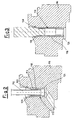
Figure 1 is a cut-away side elevation view of a connection between a cooling pipe and a straight through-hole formed in a nozzle support ring of a gas turbine, with a heat screening device according to the prior art inserted therein; -
Figure 2 shows a sectioned side elevation view of a connection between a cooling pipe and a through-hole, having two inclined sections formed in a nozzle support ring of a gas turbine, in one section there being inserted an easy-fit heat screening device according to the present invention; -
Figure 3 shows a sectioned side elevation view of a connection between a cooling pipe and a straight through-hole formed in a nozzle support ring of a gas turbine, where a system for fixing a heat screening device according to the present invention using a mounting tool is shown; -
Figure 4 shows an enlarged view ofFigure 3 illustrating a top end of the heat screening device according to the present invention, after use of a mounting tool; -
Figure 5 shows an enlarged view ofFigure 3 illustrating a top end of the heat screening device according to the present invention, before use of a mounting tool. - With reference to
Figure 1 , a heat screening device according to the prior art is indicated overall by 10, said device being intended to join together acooling pipe 12 and straight through-hole 14 formed in anozzle support ring 16 of a gas turbine. - In the example according to
Figure 1 , thescreening device 10 comprises a tubular structure 18 having atop end 20 with an external diameter approximately equal to an internal diameter of the through-hole 14. - This tubular structure 18 is inserted from the outside of the
nozzle support ring 16 and is arranged at a bottom end of the through-hole 14, being locked there by aring nut 22 mounted on the inside of thesaid ring 16 so as to support the overlying tubular structure 18. - A bottom - generally spherical - end of the
cooling pipe 12 extends inside the tubular structure 18. -
Figures 2, 3 ,4 and 5 illustrate an easy-fitheat screening device 110, according to the present invention, for connecting acooling pipe 112 and a through-hole 114 formed in anozzle support ring 116 of a gas turbine, where components identical/or equivalent to those illustrated inFigure 1 have the same reference numbers increased of 100. - More precisely,
Figure 2 shows a through-hole 114 having two sections inclined with respect to each other, whereasFigure 3 shows a straight through-hole 114. - In both cases and as can be clearly seen in
Figure 5 , an upper zone of the through-hole 114 has agroove 130. Thegroove 130 is defined at the bottom by a firstflat surface 132 which is substantially perpendicular to the axis of this upper zone and at the top by asecond surface 134 having an inclination along a line directed towards an outer extension of thefirst surface 132. - The upper zone of the through-
hole 114 has, above thegroove 130, a first internal diameter greater than a second internal diameter provided underneath the saidgroove 130. - The
screening device 110 comprises atubular structure 118. Thistubular structure 118 is inserted from the outside of thenozzle support ring 116 and is arranged inside the through-hole 114. - The
tubular structure 118 has at the bottom anannular end 124 with an external diameter which is approximately equal to the second internal diameter of the through-hole 114. - At the top, the
tubular structure 118 has a shapedannular end 126. - As can be clearly seen in
Figure 5 , an external surface of the shapedannular end 126 is formed with two different diameters. At the top a first externalcylindrical surface 128 is provided, said surface having a diameter slightly smaller than the first internal diameter of the through-hole 114. At the bottom there is a second externalcylindrical surface 129, with a diameter slightly smaller than the second internal diameter of the through-hole 114. - The first external
cylindrical surface 128 is joined to the second externalcylindrical surface 129 by a flatannular surface 127 which extends substantially perpendicularly with respect to the axis of the upper zone of the through-hole 114. - Finally, the shaped
annular end 126 terminates at the top in asurface 125, having an inclination along a line directed towards an outer extension of the flatannular surface 127. - A bottom - generally spherical - end of the
cooling pipe 112 extends inside thetubular structure 118. - The operating principle of the easy-fit
heat screening device 110 for connecting acooling pipe 112 and a through-hole 114 formed in anozzle support ring 116 of a gas turbine, according to the present invention, is clear from that described above with reference to the figures and briefly is as follows. - The
heat screening device 110 is inserted, from outside of thenozzle support ring 116, into the upper zone of the through-hole 114. Insertion is performed so that the flatannular surface 127 mates with the firstflat surface 132 of thegroove 130. - At this point, in order to lock the
heat screening device 110 inside the through-hole 114, the shapedannular end 126 is engaged inside thegroove 130. - More precisely, the shaped
annular end 126 is bent, as can be seen inFigure 3 , using for example a mounting tool with a conical end which is inserted from the outside of thenozzle support ring 116. - After this operation, as shown in
Figure 4 , the shapedannular end 126 enters partly inside thegroove 130; in particular, thesurface 125 of the shapedannular end 126 engages in an interfering manner with part of thesecond surface 134. - It is clear that the first external
cylindrical surface 128 is designed with dimensions suitable for this purpose: the inclination of thesecond surface 134 is also approximately parallel to the inclination of thesurface 125 of the shapedannular end 126 such that, after bending of the shapedannular end 126, thesurface 125 makes firm contact with thesecond surface 134. - The
heat screening device 110 advantageously uses an oil-hydraulic apparatus equipped with the conical-end mounting tool and able to generate a thrust, for example, of 10,000 Newton. - It should be noted how, in order to lock the
device 110, it is necessary to act exclusively on the outside of thenozzle support ring 116. - It must also be pointed out how the material from which the
heat screening device 110 according to the invention is made must have, in addition to heat resistance characteristics, also good plastic deformation properties required for bending of the shapedannular end 126. - The description provided clearly illustrates the characteristic features of the easy-fit heat screening device for connecting a cooling pipe and a through-hole formed in a nozzle support ring of a gas turbine according to the present invention, as well as the advantages associated therewith, including:
- simple installation and maintenance;
- reliability;
- lower costs, compared to the prior art, since there is a single heat screening device suitable for both a straight cooling pipe and a pipe with two sections inclined relative to each other: the reduction in the costs arises from the fact that use of the device according to the invention, although it requires a special tool, is industrially more simple than the prior art where it was required to perform a final safety spot weld.
Claims (6)
- An easy-fit heat screening device (110) for connecting a cooling pipe (112) and a through-hole (114) formed in a nozzle support ring (116) of a gas turbine, of the type comprising a tubular structure (118) which has an external diameter generally smaller than a diameter of said through-hole (114) and into which said cooling pipe (112) extends, characterized in that said tubular structure (118) has at the top a shaped annular end (126) which is shaped for insertion by means of interference into an annular groove (130) formed in the inner wall of said through-hole (114), said groove (130) being formed in an upper zone of said through-hole (114), said groove (130) being defined at the bottom by a first flat surface (132) and at the top by a second surface (134), the second surface having an inclination along a line directed towards an outer extension of said first flat surface (132).
- Heat screening device (110) according to Claim 1, further characterized in that said first flat surface (132) is substantially perpendicular to the axis of said upper zone of said through-hole (114), said upper zone of said through-hole (114) having, above said groove (130), a first internal diameter which is greater than a second internal diameter provided underneath said groove (130).
- Heat screening device (110) according to Claim 2, further characterized in that an external surface of said shaped annular end (126) is formed with two different diameters, at the top there being provided a first external cylindrical surface (128), with a diameter slightly smaller than said first internal diameter of said through-hole (114), and at the bottom there being a second external cylindrical surface (129), with a diameter slightly smaller than said second internal diameter of said through-hole (114).
- Heat screening device (110) according to Claim 3, further characterized in that said first external cylindrical surface (128) is joined to said second external cylindrical surface (129) by a flat annular surface (127) which extends substantially perpendicularly with respect to the axis of said upper zone of said through-hole (114).
- Heat screening device (110) according to Claim 4, further characterized in that said shaped annular end (126) terminates at the top in a surface (125) with an inclination along a line directed towards an outer
extension of said flat annular surface (127). - Heat screening device (110) according to Claim 5, further characterized in that it is inserted, from the outside of said nozzle support ring (116), into said upper zone of the through-hole (114), insertion being performed so that said flat annular surface (127) mates with said first flat surface (132) of said groove (130).
Applications Claiming Priority (2)
| Application Number | Priority Date | Filing Date | Title |
|---|---|---|---|
| ITMI20021465 | 2002-07-03 | ||
| IT2002MI001465A ITMI20021465A1 (en) | 2002-07-03 | 2002-07-03 | EASY ASSEMBLY THERMAL SHIELDING DEVICE FOR A COUPLING BETWEEN A COOLING PIPE AND A REA THROUGH DRILLING |
Publications (3)
| Publication Number | Publication Date |
|---|---|
| EP1378632A2 EP1378632A2 (en) | 2004-01-07 |
| EP1378632A3 EP1378632A3 (en) | 2005-11-23 |
| EP1378632B1 true EP1378632B1 (en) | 2015-03-11 |
Family
ID=11450134
Family Applications (1)
| Application Number | Title | Priority Date | Filing Date |
|---|---|---|---|
| EP03254222.7A Expired - Lifetime EP1378632B1 (en) | 2002-07-03 | 2003-07-02 | Easy-fit heat screening device for connecting a cooling pipe and a through-hole formed in a nozzle support ring of a gas turbine |
Country Status (8)
| Country | Link |
|---|---|
| US (1) | US6890147B2 (en) |
| EP (1) | EP1378632B1 (en) |
| JP (1) | JP4307920B2 (en) |
| KR (1) | KR100790627B1 (en) |
| CN (1) | CN100520012C (en) |
| CA (1) | CA2432816C (en) |
| IT (1) | ITMI20021465A1 (en) |
| NO (1) | NO20033033L (en) |
Families Citing this family (12)
| Publication number | Priority date | Publication date | Assignee | Title |
|---|---|---|---|---|
| DE102004014117A1 (en) * | 2004-03-23 | 2005-10-13 | Alstom Technology Ltd | Component of a turbomachine with a cooling arrangement |
| GB0508912D0 (en) * | 2005-04-30 | 2005-06-08 | Rolls Royce Plc | Vane coupling |
| US8596959B2 (en) * | 2009-10-09 | 2013-12-03 | Pratt & Whitney Canada Corp. | Oil tube with integrated heat shield |
| US9316117B2 (en) | 2012-01-30 | 2016-04-19 | United Technologies Corporation | Internally cooled spoke |
| US9316153B2 (en) * | 2013-01-22 | 2016-04-19 | Siemens Energy, Inc. | Purge and cooling air for an exhaust section of a gas turbine assembly |
| EP2933436A1 (en) * | 2014-04-15 | 2015-10-21 | Siemens Aktiengesellschaft | Wheel disc with at least one sealing sheet metal panel |
| US9920869B2 (en) * | 2014-05-22 | 2018-03-20 | United Technologies Corporation | Cooling systems for gas turbine engine components |
| US9790860B2 (en) | 2015-01-16 | 2017-10-17 | United Technologies Corporation | Cooling passages for a mid-turbine frame |
| PL421120A1 (en) | 2017-04-04 | 2018-10-08 | General Electric Company Polska Spolka Z Ograniczona Odpowiedzialnoscia | Turbine engine and component parts to be used in it |
| FR3101372B1 (en) * | 2019-09-27 | 2021-10-01 | Safran Aircraft Engines | AIRCRAFT TURBOMACHINE |
| US11692485B2 (en) | 2021-02-18 | 2023-07-04 | Generai, Electric Company | Gas turbine engine with spoolie fluid transfer connection |
| US12698722B2 (en) | 2022-11-01 | 2026-08-04 | General Electric Company | Gas turbine engine |
Family Cites Families (10)
| Publication number | Priority date | Publication date | Assignee | Title |
|---|---|---|---|---|
| US3370830A (en) | 1966-12-12 | 1968-02-27 | Gen Motors Corp | Turbine cooling |
| US3574354A (en) * | 1969-05-08 | 1971-04-13 | Avica Corp | Flexible coupling |
| US5224818A (en) | 1991-11-01 | 1993-07-06 | General Electric Company | Air transfer bushing |
| US5517817A (en) * | 1993-10-28 | 1996-05-21 | General Electric Company | Variable area turbine nozzle for turbine engines |
| CA2263508C (en) * | 1997-06-19 | 2003-08-19 | Mitsubishi Heavy Industries, Ltd. | Sealing device for gas turbine stator blades |
| JP3564290B2 (en) | 1997-12-24 | 2004-09-08 | 三菱重工業株式会社 | Steam-cooled gas turbine |
| ITMI991208A1 (en) * | 1999-05-31 | 2000-12-01 | Nuovo Pignone Spa | DEVICE FOR THE POSITIONING OF NOZZLES OF A STATIC STAGE AND FOR THE COOLING OF ROTOR DISCS IN GAS TURBINES |
| US6382906B1 (en) * | 2000-06-16 | 2002-05-07 | General Electric Company | Floating spoolie cup impingement baffle |
| JP2002155703A (en) | 2000-11-21 | 2002-05-31 | Mitsubishi Heavy Ind Ltd | Seal structure of steam passage between gas turbine stator blade and blade ring |
| ITMI20020910A1 (en) * | 2002-04-29 | 2003-10-29 | Nuovo Pignone Spa | SEALING DEVICE FOR COUPLING A PIPE WITH A HOLE |
-
2002
- 2002-07-03 IT IT2002MI001465A patent/ITMI20021465A1/en unknown
-
2003
- 2003-06-19 CA CA2432816A patent/CA2432816C/en not_active Expired - Fee Related
- 2003-06-30 US US10/608,553 patent/US6890147B2/en not_active Expired - Lifetime
- 2003-07-01 JP JP2003189148A patent/JP4307920B2/en not_active Expired - Lifetime
- 2003-07-02 EP EP03254222.7A patent/EP1378632B1/en not_active Expired - Lifetime
- 2003-07-02 NO NO20033033A patent/NO20033033L/en unknown
- 2003-07-02 KR KR1020030044496A patent/KR100790627B1/en not_active Expired - Lifetime
- 2003-07-03 CN CNB03145304XA patent/CN100520012C/en not_active Expired - Lifetime
Also Published As
| Publication number | Publication date |
|---|---|
| KR100790627B1 (en) | 2007-12-31 |
| JP2004052765A (en) | 2004-02-19 |
| EP1378632A3 (en) | 2005-11-23 |
| US20040057825A1 (en) | 2004-03-25 |
| CA2432816C (en) | 2010-11-09 |
| US6890147B2 (en) | 2005-05-10 |
| NO20033033L (en) | 2004-01-05 |
| JP4307920B2 (en) | 2009-08-05 |
| CN1495341A (en) | 2004-05-12 |
| CN100520012C (en) | 2009-07-29 |
| KR20040004125A (en) | 2004-01-13 |
| EP1378632A2 (en) | 2004-01-07 |
| ITMI20021465A0 (en) | 2002-07-03 |
| ITMI20021465A1 (en) | 2004-01-05 |
| NO20033033D0 (en) | 2003-07-02 |
| CA2432816A1 (en) | 2004-01-03 |
Similar Documents
| Publication | Publication Date | Title |
|---|---|---|
| US11662095B2 (en) | Fuel nozzle and combustor and gas turbine including the same | |
| US6890147B2 (en) | Easy-fit heat screening device for connecting a cooling pipe and a through-hole formed in a nozzle support ring of a gas turbine | |
| US10934864B2 (en) | Apparatus for axial locking of bucket and bucket assembly and gas turbine having the same | |
| US20220228741A1 (en) | Nozzle assembly, combustor, and gas turbine having same | |
| US10982593B2 (en) | System and method for combusting liquid fuel in a gas turbine combustor with staged combustion | |
| CN113154391B (en) | Gas-oxygen-methane torch ignition device and torch generation method thereof | |
| US11608985B2 (en) | Combustor and gas turbine including the same | |
| KR20190108955A (en) | Fuel injection device for gas turbine, fuelnozzle and gas turbinehaving it | |
| JP4424553B2 (en) | Jet burner | |
| KR20190037492A (en) | Fuel nozzle, combustor and gas turbine having the same | |
| KR102047369B1 (en) | Fuel nozzle, combustor and gas turbine having the same | |
| US12546472B2 (en) | Dome-deflector joint cooling arrangement | |
| JP2020201033A (en) | Cross fire tube installation/removal methods and apparatus | |
| EP3477203B1 (en) | Combustor and gas turbine including the same | |
| KR20200004455A (en) | Fuel nozzle, combustor and gas turbine having the same | |
| KR102021128B1 (en) | Combustor and gas turbine comprising the same | |
| KR102021129B1 (en) | Fuel nozzle, combustor and gas turbine having the same | |
| JP4646039B2 (en) | A structure that separates the internal regions of high and low pressure turbines. | |
| KR20220104493A (en) | Nozzle assembly, combustor and gas turbine comprising the same | |
| CN119844798B (en) | Flame tube, combustion chamber and aircraft engine | |
| KR102047368B1 (en) | Fuel nozzle, combustor and gas turbine having the same | |
| US11060727B2 (en) | Fuel nozzle assembly and gas turbine including the same | |
| KR101842745B1 (en) | Connecting device of transition piece and turbine of gas turbine | |
| WO2002027169A1 (en) | A connecting device | |
| CN117365782A (en) | A gas generator with uniform mixing and reliable combustion |
Legal Events
| Date | Code | Title | Description |
|---|---|---|---|
| PUAI | Public reference made under article 153(3) epc to a published international application that has entered the european phase |
Free format text: ORIGINAL CODE: 0009012 |
|
| AK | Designated contracting states |
Kind code of ref document: A2 Designated state(s): AT BE BG CH CY CZ DE DK EE ES FI FR GB GR HU IE IT LI LU MC NL PT RO SE SI SK TR |
|
| AX | Request for extension of the european patent |
Extension state: AL LT LV MK |
|
| PUAL | Search report despatched |
Free format text: ORIGINAL CODE: 0009013 |
|
| AK | Designated contracting states |
Kind code of ref document: A3 Designated state(s): AT BE BG CH CY CZ DE DK EE ES FI FR GB GR HU IE IT LI LU MC NL PT RO SE SI SK TR |
|
| AX | Request for extension of the european patent |
Extension state: AL LT LV MK |
|
| RIC1 | Information provided on ipc code assigned before grant |
Ipc: 7F 01D 25/08 B Ipc: 7F 01D 9/06 A Ipc: 7F 01D 11/00 B |
|
| 17P | Request for examination filed |
Effective date: 20060523 |
|
| AKX | Designation fees paid |
Designated state(s): CH DE FR GB LI NL |
|
| 17Q | First examination report despatched |
Effective date: 20060915 |
|
| 17Q | First examination report despatched |
Effective date: 20060915 |
|
| GRAP | Despatch of communication of intention to grant a patent |
Free format text: ORIGINAL CODE: EPIDOSNIGR1 |
|
| INTG | Intention to grant announced |
Effective date: 20141020 |
|
| GRAS | Grant fee paid |
Free format text: ORIGINAL CODE: EPIDOSNIGR3 |
|
| GRAA | (expected) grant |
Free format text: ORIGINAL CODE: 0009210 |
|
| AK | Designated contracting states |
Kind code of ref document: B1 Designated state(s): CH DE FR GB LI NL |
|
| REG | Reference to a national code |
Ref country code: GB Ref legal event code: FG4D |
|
| REG | Reference to a national code |
Ref country code: CH Ref legal event code: EP |
|
| REG | Reference to a national code |
Ref country code: DE Ref legal event code: R096 Ref document number: 60347391 Country of ref document: DE Effective date: 20150423 |
|
| REG | Reference to a national code |
Ref country code: FR Ref legal event code: PLFP Year of fee payment: 13 |
|
| PGFP | Annual fee paid to national office [announced via postgrant information from national office to epo] |
Ref country code: NL Payment date: 20150726 Year of fee payment: 13 |
|
| PGFP | Annual fee paid to national office [announced via postgrant information from national office to epo] |
Ref country code: CH Payment date: 20150914 Year of fee payment: 13 |
|
| PGFP | Annual fee paid to national office [announced via postgrant information from national office to epo] |
Ref country code: FR Payment date: 20150717 Year of fee payment: 13 |
|
| REG | Reference to a national code |
Ref country code: DE Ref legal event code: R097 Ref document number: 60347391 Country of ref document: DE |
|
| PLBE | No opposition filed within time limit |
Free format text: ORIGINAL CODE: 0009261 |
|
| STAA | Information on the status of an ep patent application or granted ep patent |
Free format text: STATUS: NO OPPOSITION FILED WITHIN TIME LIMIT |
|
| 26N | No opposition filed |
Effective date: 20151214 |
|
| REG | Reference to a national code |
Ref country code: CH Ref legal event code: PL |
|
| REG | Reference to a national code |
Ref country code: NL Ref legal event code: MM Effective date: 20160801 |
|
| PG25 | Lapsed in a contracting state [announced via postgrant information from national office to epo] |
Ref country code: CH Free format text: LAPSE BECAUSE OF NON-PAYMENT OF DUE FEES Effective date: 20160731 Ref country code: LI Free format text: LAPSE BECAUSE OF NON-PAYMENT OF DUE FEES Effective date: 20160731 Ref country code: NL Free format text: LAPSE BECAUSE OF NON-PAYMENT OF DUE FEES Effective date: 20160801 Ref country code: FR Free format text: LAPSE BECAUSE OF NON-PAYMENT OF DUE FEES Effective date: 20160801 |
|
| REG | Reference to a national code |
Ref country code: FR Ref legal event code: ST Effective date: 20170331 |
|
| REG | Reference to a national code |
Ref country code: GB Ref legal event code: 732E Free format text: REGISTERED BETWEEN 20220414 AND 20220420 |
|
| PGFP | Annual fee paid to national office [announced via postgrant information from national office to epo] |
Ref country code: GB Payment date: 20220621 Year of fee payment: 20 |
|
| REG | Reference to a national code |
Ref country code: GB Ref legal event code: 732E Free format text: REGISTERED BETWEEN 20220728 AND 20220803 |
|
| PGFP | Annual fee paid to national office [announced via postgrant information from national office to epo] |
Ref country code: DE Payment date: 20220621 Year of fee payment: 20 |
|
| REG | Reference to a national code |
Ref country code: DE Ref legal event code: R071 Ref document number: 60347391 Country of ref document: DE |
|
| REG | Reference to a national code |
Ref country code: GB Ref legal event code: PE20 Expiry date: 20230701 |
|
| PG25 | Lapsed in a contracting state [announced via postgrant information from national office to epo] |
Ref country code: GB Free format text: LAPSE BECAUSE OF EXPIRATION OF PROTECTION Effective date: 20230701 |