EP1378406A2 - Apparatus for restricting activation of engine starting system - Google Patents
Apparatus for restricting activation of engine starting system Download PDFInfo
- Publication number
- EP1378406A2 EP1378406A2 EP20030445064 EP03445064A EP1378406A2 EP 1378406 A2 EP1378406 A2 EP 1378406A2 EP 20030445064 EP20030445064 EP 20030445064 EP 03445064 A EP03445064 A EP 03445064A EP 1378406 A2 EP1378406 A2 EP 1378406A2
- Authority
- EP
- European Patent Office
- Prior art keywords
- actuator
- lock position
- operating means
- vehicle
- control means
- Prior art date
- Legal status (The legal status is an assumption and is not a legal conclusion. Google has not performed a legal analysis and makes no representation as to the accuracy of the status listed.)
- Granted
Links
Images





Classifications
-
- F—MECHANICAL ENGINEERING; LIGHTING; HEATING; WEAPONS; BLASTING
- F02—COMBUSTION ENGINES; HOT-GAS OR COMBUSTION-PRODUCT ENGINE PLANTS
- F02N—STARTING OF COMBUSTION ENGINES; STARTING AIDS FOR SUCH ENGINES, NOT OTHERWISE PROVIDED FOR
- F02N11/00—Starting of engines by means of electric motors
- F02N11/10—Safety devices
-
- B—PERFORMING OPERATIONS; TRANSPORTING
- B60—VEHICLES IN GENERAL
- B60R—VEHICLES, VEHICLE FITTINGS, OR VEHICLE PARTS, NOT OTHERWISE PROVIDED FOR
- B60R25/00—Fittings or systems for preventing or indicating unauthorised use or theft of vehicles
- B60R25/20—Means to switch the anti-theft system on or off
- B60R25/2063—Ignition switch geometry
-
- B—PERFORMING OPERATIONS; TRANSPORTING
- B60—VEHICLES IN GENERAL
- B60R—VEHICLES, VEHICLE FITTINGS, OR VEHICLE PARTS, NOT OTHERWISE PROVIDED FOR
- B60R25/00—Fittings or systems for preventing or indicating unauthorised use or theft of vehicles
- B60R25/01—Fittings or systems for preventing or indicating unauthorised use or theft of vehicles operating on vehicle systems or fittings, e.g. on doors, seats or windscreens
- B60R25/04—Fittings or systems for preventing or indicating unauthorised use or theft of vehicles operating on vehicle systems or fittings, e.g. on doors, seats or windscreens operating on the propulsion system, e.g. engine or drive motor
-
- Y—GENERAL TAGGING OF NEW TECHNOLOGICAL DEVELOPMENTS; GENERAL TAGGING OF CROSS-SECTIONAL TECHNOLOGIES SPANNING OVER SEVERAL SECTIONS OF THE IPC; TECHNICAL SUBJECTS COVERED BY FORMER USPC CROSS-REFERENCE ART COLLECTIONS [XRACs] AND DIGESTS
- Y10—TECHNICAL SUBJECTS COVERED BY FORMER USPC
- Y10S—TECHNICAL SUBJECTS COVERED BY FORMER USPC CROSS-REFERENCE ART COLLECTIONS [XRACs] AND DIGESTS
- Y10S70/00—Locks
- Y10S70/30—Switch lock
-
- Y—GENERAL TAGGING OF NEW TECHNOLOGICAL DEVELOPMENTS; GENERAL TAGGING OF CROSS-SECTIONAL TECHNOLOGIES SPANNING OVER SEVERAL SECTIONS OF THE IPC; TECHNICAL SUBJECTS COVERED BY FORMER USPC CROSS-REFERENCE ART COLLECTIONS [XRACs] AND DIGESTS
- Y10—TECHNICAL SUBJECTS COVERED BY FORMER USPC
- Y10T—TECHNICAL SUBJECTS COVERED BY FORMER US CLASSIFICATION
- Y10T70/00—Locks
- Y10T70/50—Special application
- Y10T70/5611—For control and machine elements
- Y10T70/5646—Rotary shaft
- Y10T70/565—Locked stationary
- Y10T70/5655—Housing-carried lock
- Y10T70/5664—Latching bolt
-
- Y—GENERAL TAGGING OF NEW TECHNOLOGICAL DEVELOPMENTS; GENERAL TAGGING OF CROSS-SECTIONAL TECHNOLOGIES SPANNING OVER SEVERAL SECTIONS OF THE IPC; TECHNICAL SUBJECTS COVERED BY FORMER USPC CROSS-REFERENCE ART COLLECTIONS [XRACs] AND DIGESTS
- Y10—TECHNICAL SUBJECTS COVERED BY FORMER USPC
- Y10T—TECHNICAL SUBJECTS COVERED BY FORMER US CLASSIFICATION
- Y10T70/00—Locks
- Y10T70/50—Special application
- Y10T70/5889—For automotive vehicles
-
- Y—GENERAL TAGGING OF NEW TECHNOLOGICAL DEVELOPMENTS; GENERAL TAGGING OF CROSS-SECTIONAL TECHNOLOGIES SPANNING OVER SEVERAL SECTIONS OF THE IPC; TECHNICAL SUBJECTS COVERED BY FORMER USPC CROSS-REFERENCE ART COLLECTIONS [XRACs] AND DIGESTS
- Y10—TECHNICAL SUBJECTS COVERED BY FORMER USPC
- Y10T—TECHNICAL SUBJECTS COVERED BY FORMER US CLASSIFICATION
- Y10T70/00—Locks
- Y10T70/50—Special application
- Y10T70/5889—For automotive vehicles
- Y10T70/5925—Transmission
- Y10T70/5934—Selective-type shift rod, fork or block
-
- Y—GENERAL TAGGING OF NEW TECHNOLOGICAL DEVELOPMENTS; GENERAL TAGGING OF CROSS-SECTIONAL TECHNOLOGIES SPANNING OVER SEVERAL SECTIONS OF THE IPC; TECHNICAL SUBJECTS COVERED BY FORMER USPC CROSS-REFERENCE ART COLLECTIONS [XRACs] AND DIGESTS
- Y10—TECHNICAL SUBJECTS COVERED BY FORMER USPC
- Y10T—TECHNICAL SUBJECTS COVERED BY FORMER US CLASSIFICATION
- Y10T70/00—Locks
- Y10T70/50—Special application
- Y10T70/5889—For automotive vehicles
- Y10T70/5956—Steering mechanism with switch
Definitions
- the present invention relates to an apparatus for restricting activation of an engine starting system.
- interlocking mechanisms are included in automobiles for safety reasons.
- an interlocking mechanism restricts the activation of a steering lock apparatus by preventing a key inserted into a key cylinder from being removed.
- An electric interlocking mechanism includes a key interlocking solenoid to permit or prohibit the insertion of the key.
- a smart ignition apparatus has been proposed to permit the starting of an engine when an ID code stored in a portable device matches an ID code stored in the automobile.
- the smart ignition apparatus includes a knob locking solenoid to permit or prohibit the turning of a starter knob.
- the smart ignition apparatus uses an ID code that provides a higher degree of confidentiality than a mechanical key.
- the smart ignition apparatus is highly effective for preventing thefts.
- an elongated cover for entirely covering the engine starting system may be used in both automobiles equipped with the smart ignition apparatus and automobiles that are not equipped with the smart ignition apparatus.
- the knob locking solenoid becomes necessary in addition to the key interlocking solenoid.
- space for the knob locking solenoid is required in addition to the space for the key interlocking solenoid. This enlarges the entire engine starting system.
- the elongated cover that covers the engine starting system cannot be used when two solenoids are used. As a result, two types of elongated covers are necessary, and the manufacturing cost of the engine starting system cannot be reduced.
- an apparatus for restricting activation of a starting system of an engine of a vehicle and for use with a portable device that transmits a first ID code includes an operating means for manually starting and stopping the engine and having a plurality of operation positions including a LOCK position in which the operating means is locked.
- the operating means includes a first stopper, which prohibits movement of the operating means from the LOCK position to a position other than the LOCK position, and a second stopper, which prohibits movement of the operating means to the LOCK position from a position other than the LOCK position.
- An actuator engages the first and second stoppers.
- a control means is connected to the actuator to control the actuator.
- the control means enables the engine to be started by disengaging the actuator from the first stopper when the operating means is in the LOCK position and the first ID code sent from the portable device matches a predetermined second ID code of the control means.
- the control means enables the operating means to be moved to the LOCK position by disengaging the actuator from the second stopper when the operating means is in a position other than the LOCK position and the vehicle is not moving.
- an apparatus for restricting activation of a starting system of an engine of a vehicle and for use with a portable device operable for sending a first ID code includes an operating means for manually starting and stopping the engine and having a plurality of operation positions including a LOCK position in which the operating means is locked.
- the operating means includes a first projection, which prohibits movement of the operating means from the LOCK position to a position other than the LOCK position, and a second projection, which prohibits movement of the operating means to the LOCK position from a position other than the LOCK position.
- An actuator engages the first and second stoppers.
- An intervening member is arranged between the actuator and the second projection to engage the second projection in cooperation with the actuator.
- An actuator control means is connected to the actuator to control the actuator.
- An ID code verification means is connected to the actuator control means to determine whether the first ID code when sent from the portable device matches a second ID code.
- a shift lock control means is connected to the actuator for enabling the operating means to be moved to the LOCK position by disengaging the intervening member from the second projection when the operating means is in a position other than the LOCK position and the vehicle is not moving.
- the actuator control means enables the engine to be started by disengaging the actuator from the first projection when the operating means is in the LOCK position and the first ID code matches the second ID code.
- Figs. 1A to 1C are schematic cross-sectional diagrams showing an activation restricting apparatus 100 of an engine starting system 11 according to a first embodiment of the present invention.
- the engine starting system 11 has a metal cylinder 13.
- An immobilizer amplifier 17 is connected to a lower surface of the cylinder 13.
- the cylinder 13 includes a bore 14 and an accommodating portion 16, which is connected with the bore 14.
- a camshaft 21 is retained in the bore 14.
- a starter knob 22 is connected to one end of the camshaft 21.
- the starter knob 22 is turned between an ACC position and a LOCK position.
- the starter knob 22 includes a tab 22a.
- the tab 22a is used to turn the starter knob 22. This rotates the camshaft 21 and starts or stops the engine.
- the camshaft 21 and the starter knob 22 function as an operating means.
- the camshaft 21 includes a cam 31.
- a first projection 32a which serves as a first stopper
- a second projection 32b which serves as a second stopper, extend from the surface of the cam 31.
- the first projection 32a restricts the movement of the starter knob 22 to the ACC position.
- the second projection 32b restricts the movement of the starter knob 22 to the LOCK position.
- a solenoid 41 which serves as an actuator, is attached to the cylinder 13.
- the solenoid 41 includes a plunger 42.
- a stopper pin 43 is connected to the plunger 42 by a damper 42a.
- the stopper pin 43 extends vertically in the accommodating portion 16, as viewed in Figs 1A to 1C. Further, the stopper pin 43 is movable in the vertical direction.
- the stopper pin 43 When the solenoid 41 is de-excited (inactivated) as shown in the state of Figs. 1A and 1B, the stopper pin 43 is projected to engage the first projection 32a. When the solenoid 41 is excited (activated) as shown in the state of Fig. 1C, the stopper pin 43 is retracted and disengaged from the first projection 32a. The stopper pin 43 engages the first projection 32a, for example, when the camshaft 21 is arranged at the LOCK position as shown in the state of Fig. 1B.
- a locking lever (second stopper) 44 which serves as an intervening member, is connected to the cylinder 13.
- the locking lever 44 is pivoted about a pivot pin 44a.
- the locking lever 44 has a first end (left end as viewed in Fig. 2) and a second end (right end as viewed in Fig. 2).
- the damper 42a pushes the locking lever 44 toward the first projection 32a. This moves the second end of the locking lever 44 away from the second projection 32b.
- An engaging spring 47 constantly urges the second end of the locking lever 44 toward the second projection 32b.
- a force is applied to the first end of the locking lever 44 in a direction in which the first end disengages the first projection 32a.
- the cylinder 13 has a switch 45, which serves as switching means.
- the switch 45 goes ON and OFF when the starter knob 22 is turned between the LOCK position and the ACC position. Accordingly, the switch 45 activates and inactivates the solenoid 41.
- a block 46 (cooperative member) contacts or moves away from a contact 45a of the switch 45 to activate or inactivate the solenoid 41.
- the switch 45 goes OFF and the solenoid 41 is inactivated.
- the solenoid 41 is activated.
- a spring urges the block 46 toward the contact 45a of the switch 45.
- a cam follower 46a projects from the block 46 to engage a cam surface 31a of the cam 31. The portion of the cam surface 31a that contacts the cam follower 46a moves in the axial direction of the starter knob 22 in accordance with the turning of the starter knob 22. In other words, the block 46 moves axially in accordance with the turning of the starter knob 22.
- the engine starting system 11 includes a portable device 51, a communication controller 61, the solenoid 41, a solenoid electronic control unit (ECU) 71, a switch 45, and a shift lock controller 81.
- the portable device 51 includes a receiving circuit 52, a microcomputer 53, a transmitting circuit 54, and a transponder controller 55.
- the receiving circuit 52 receives a request signal from the communication controller 61 and provides the request signal to the microcomputer 53.
- the microcomputer 53 When receiving the request signal, the microcomputer 53 generates an ID code signal.
- the ID code signal includes a predetermined ID code and serves as a transmission signal.
- the transmitting circuit 54 uses the ID code signal to modulate a wave having a predetermined frequency and transmits the modulated wave to an external device.
- the receiving circuit 52 and the transmitting circuit 54 are respectively connected to antennas 52a and 54a.
- the transponder controller 55 When the transponder controller 55 receives sufficient energy through electromagnetic waves, the transponder controller 55 generates a transponder signal, which includes a predetermined transponder ID code. More specifically, the transponder controller 55 automatically generates a transponder signal having a predetermined frequency when receiving a transponder drive wave from the communication controller. Then, the transponder controller 55 transmits the transponder signal to the communication controller 61.
- the communication controller 61 which is installed in the vehicle, includes a transmitting circuit 62, a first receiving circuit 63, a second receiving circuit 64, a switching circuit 65, and a smart ECU 66.
- the smart ECU 66 serves as a control means and an ID code verification means.
- the smart ECU 66 is connected to the first receiving circuit 63, the transmitting circuit 62, and the second receiving circuit 64.
- the first receiving circuit 63 is connected to an antenna.
- the transmitting circuit 62 and the second receiving circuit 64 are connected to the switching circuit 65.
- the switching circuit 65 selectively connects the immobilizer amplifier 17 and the antenna 17a to the transmitting circuit 62 and the second receiving circuit 64.
- the immobilizer amplifier 17 amplifies the transponder signal received by the antenna 17a and provides the amplified transponder signal to the second receiving circuit 64.
- the transmitting circuit 62 is connected to an antenna 62a, which is installed in the passenger compartment.
- the transmitting circuit 62 sends a request signal to the passenger compartment through the antenna 62a.
- the transmitting circuit 62 converts the transponder signal provided from the smart ECU 66 to a wave having a predetermined frequency and generates a transponder drive wave.
- the transponder drive wave is output through the antenna 17a.
- the second receiving circuit 64 receives a transponder signal from the portable device 51 through the antenna 17a. Then, the second receiving circuit 64 de-modulates the transponder signal to a pulse signal and generates a second receiving signal. The second receiving signal is provided to the smart ECU 66.
- the solenoid ECU 71 which serves as a control means and an actuator drive control means, is connected to the smart ECU 66.
- the solenoid ECU 71 is connected to the solenoid 41 to control the activation of the solenoid 41.
- the solenoid ECU 71, the solenoid 41, and the switch 45 are accommodated in a lock body 12, which serves as a cover.
- the portion closed by the lock body 12 serves as a hard protect area 82 in which the solenoid ECU 71, the solenoid 41, and the switch 45 are protected from external impacts.
- the shift lock controller 81 which serves as a control means, is connected to the solenoid 41 via the switch 45 and a power line 76.
- the shift lock controller 81 detects whether the shift lever is in the parking position and whether a shift button of the shift lever is not being pressed. From the detections, the shift lock controller 81 determines whether the vehicle is not moving and inactivates the solenoid 41 even if the switch 45 is ON. As shown in Fig. 4, the solenoid 41 is supplied with power from a battery via the smart ECU 66 or the shift lock controller 81.
- the solenoid ECU 71 includes a central processing unit (CPU) 72.
- the CPU 72 is connected to the base terminal of the transistor 74 via a resistor R1.
- the collector terminal of the transistor 74 is connected to the base terminal of a transistor 74a.
- the transistors 74 and 74a amplify the power supplied to the solenoid 41 by the smart ECU 66.
- a power line 75 and a signal line 73 connect the CPU 72 and the smart ECU 66 to each other. Power is supplied to the CPU 72 through the power line 75.
- the signal line 73 us used for serial communication to send information from the smart ECU 66 to the CPU 72 on whether encoded ID codes are matched.
- the smart ECU 66 which includes a CPU, a ROM, and a RAM (none of which are shown), intermittently generates a request signal.
- the smart ECU 66 has a predetermined ID code and compares its ID code with an ID code included in the first receiving signal or the second receiving signal when receiving the first or second receiving signal. When the ID codes match, the smart ECU 66 generates an activation signal and provides the activation signal to the CPU 72. Then, the CPU 72 provides the transistor 74 with the activation signal to activate the solenoid 41.
- the smart ECU 66 determines that the portable device 51 is located in the passenger compartment and activates the solenoid 41 for five seconds.
- the portable device 51 is inserted in the tab 22a, as shown in Fig. 1A, when the power of the portable device 51 weakens or when one does not know how to operate the starter knob 22. In this state, as long as the portable device 51 generates the transponder signal in response to a transponder drive wave, the smart ECU 66 activates the solenoid 41 for five seconds.
- the plunger 42 moves and disengages the stopper pin 43 from the first projection 32a to enable the turning of the starter knob.
- the starter knob 22 is turned to move the starter knob 22 from the LOCK position to the ACC position.
- the smart ECU 66 and the solenoid ECU are inactivated.
- the turning of the starter knob 22 moves the block 46 away from the contact 45a and turns ON the switch 45, as shown in the state of Fig. 6. Since the shift lever is arranged at the parking position, the solenoid 41 returns to the inactivated state, and the stopper pin 43 projects into the bore 14.
- the starter knob 22 is pushed in the axial direction, for example, when a driver does not immediately start the engine after getting into the vehicle to again request ID code verification and to enable the turning of the starter knob 22. Since the rotation of the camshaft 21 from the ACC position to the START position is enabled as shown in the state of Fig. 8, the engine may be started by activating a starting relay (not shown) to drive a starting motor (not shown). Accordingly, the engine starting system 11 functions as a smart ignition apparatus.
- the shift lock controller 81 detects whether the vehicle is not moving when the starter knob 22 is located at the ACC position. In this state, the solenoid 41 is not activated even if the switch 45 is ON since the shift lock controller 81 does not supply the solenoid 41 with power. Thus, as shown in the state of Fig. 10, the plunger 42 moves downward and disengages the locking lever 44 from the second projection 32b to enable the turning of the starter knob 22. By turning the starter knob 22 in this state, the first projection lifts the stopper pin 43 until the starter knob 22 reaches the LOCK position. Then, as shown in the state of Fig. 2, the block 46 contacts the contact 45a and turns on the switch 45. Further, the engagement between the stopper pin 43 and the first projection 32a prohibits the turning of the starter knob 22. Accordingly, the engine starting system 11 functions as a key interlocking mechanism.
- the engine starting system activation restricting apparatus 100 of the first embodiment has the advantages described below.
- the solenoid 41 enables the starting of the engine with the starter knob 22 when the camshaft 21 is located at the LOCK position. Further, the solenoid 41 disengages the locking lever 44 from the second projection 32b when the starter knob 22 is located at a position other than the LOCK position as long as the switch 45 activates the solenoid 41 and the vehicle is not moving. This enables the starter knob 22 to be turned to the LOCK position. Thus, the same solenoid 41 is used to enable the turning of the starter knob 22 regardless of whether the starter knob 22 is located at the LOCK position or the ACC position. Thus, the solenoid 41 does not occupy much space. This enables the engine starting system 11 to be produced more compactly and improves safety with respect to collisions.
- the engine starting system 11 requires only one solenoid 41.
- the same lock body 12, which accommodates the engine starting system 11 may be used even when adding the smart ignition apparatus. This decreases the cost of the engine starting system 11.
- the activation and inactivation of the solenoid41 are performed mechanically by moving the block 46 toward or away from the block. More specifically, the solenoid 41 is inactivated when the block 46 contacts the contact 45a. The solenoid 41 is activated when the block 46 moves away from the contact 45a. This guarantees that the movement of the switch 45 is enabled.
- the switch 45 is arranged in the lock body 12. Thus, current does not flow directly to the solenoid 41 even if, for example, a thief intentionally sends current through the power line 76 as long as the switch 45 is OFF.
- the solenoid ECU 71 which includes the solenoid 41 and the CPU 72, is located in the lock body 12. Thus, current does not flow directly to the transistor 74 even if, for example, a thief intentionally sends current through the power line 75. This prevents the solenoid 41 from being improperly driven to turn the starter knob 22. Accordingly, the engine is prevented from being started by an unauthorized person. This further improves the security of the vehicle with respect to thefts.
- the smart ECU 66 and the solenoid ECU 71 are activated only when the starter knob 22 is turned from the LOCK position to the ACC position. Thus, the smart ECU 66 and the solenoid ECU 71 are inactivated when the smart ECU 66 stops outputting the activation signal. This decreases the current consumed by the engine starting system 11.
- the starter knob 22 may be pushed along its axial direction.
- the time lag that occurs when activating the solenoid 41 i.e., the time required to activated the solenoid 41
- the time lag that occurs when activating the solenoid 41 is absorbed during the period in which the starter knob 22 is pushed. This guarantees engagement between the stopper pin 43 and the first projection 32a. Accordingly, the starter knob 22 is prevented from being interfered with by the stopper pin 43.
- Fig. 11 is a cross-sectional view of an engine starting system activation restricting apparatus 200 according to a second embodiment of the present invention.
- Fig. 12 is a schematic cross-sectional view taken along line 12-12. Parts differing from the first embodiment will now be described. Identical parts will not be described.
- a cam 31A has a first recess (first stopper) 132a and a second recess (second stopper) 132b in lieu of the first and second projections 32a and 32b of the first embodiment. Further, the activation restricting apparatus 200 does not have the locking lever 44 and the switch 45 of the first embodiment.
- an engine starting system 11A includes a cylinder 13, which has an attaching portion 15 and an accommodating portion 16.
- the accommodating portion 16 is connected to a bore 14 through a plunger insertion hole 16a.
- a stopper pin 43 extends vertically through the accommodating portion 16.
- a spring 144 urges the stopper pin 43 upward, as viewed in Fig. 12.
- the first and second recesses 132a and 132b are arranged in the surface of the cam 31A.
- the dimension of the second recess 132b in the circumferential direction of the cam 31A is greater than that of the first recess 132a.
- the first recess 132a corresponds to the LOCK position of a starter knob 22.
- the second recess 132b corresponds to positions of the starter knob 22 other than the LOCK position (i.e., ACC position, ON position, and START position).
- the stopper pin 43 is engaged with and disengaged from the first recess 132a or the second recess 132b by the solenoid 41. More specifically, when the solenoid 41 is inactivated, the stopper pin 43 is held in a state engaged with the first recess 132a or the second recess 132b. When the solenoid 41 is activated, the stopper pin 43 is disengaged from the first recess 132a or the second recess 132b. When a camshaft 21 is located at a position corresponding to the LOCK position, the stopper pin 43 engages the first recess 132a. As shown in the state of Fig. 15C, when the camshaft 21 is located at the ACC position, the stopper pin 43 engages the second recess 132b.
- the portable device 51 includes a receiving circuit, a microcomputer 53, a transmitting circuit 54, and a transponder controller 55.
- the communication controller 61 which is installed in a vehicle, includes a transmitting circuit 62, a first receiving circuit 63, a second receiving circuit 64, a switching circuit 65, and a smart ECU 66, which serves as a control means.
- a shift lock controller 81 which serves as a control means, is connected to the smart ECU 66.
- the shift lock controller 81 detects whether a shift lever of the automatic transmission for the vehicle is in the parking position and whether a shift button arranged on the shift lever is not being pressed. From the detections, the shift lock controller 81 determines whether the vehicle is not moving and generates a vehicle stop signal. The vehicle stop signal is provided to the smart ECU 66.
- the smart ECU 66 us connected to a solenoid ECU 71A, which controls the activation of the solenoid 41. Referring to Fig. 14, the smart ECU 66 supplies the solenoid 41 with power.
- the solenoid ECU 71A includes a CPU 72.
- the CPU 72 is connected to the base terminal of a transistor 74 via a resistor R1.
- the smart ECU 66 determines that the portable device 51 is located in the passenger compartment and activates the solenoid 41 for five seconds.
- the turning of the starter knob 22 from the ACC position to the START position is enabled.
- the engine may be started by activating a starting relay (not shown) to drive a starting motor (not shown).
- the engine starting system 11A functions as a smart ignition apparatus.
- the solenoid ECU 71A activates the solenoid 41 when the starter knob 22 is located at the ACC position as long as the vehicle is not moving. More specifically, the CPU 72 generates an activation signal in accordance with a vehicle stop signal from the shift lock controller 81 and provides the transistor 74 with the activation signal. The transistor 74 activates the solenoid 41 in response to the activation signal. This moves the plunger 42 and disengages the stopper pin 43 from the second recess 132b to enable turning of the starter knob 22. From this state, the starter knob 22 is pushed in the axial direction and then turned to the LOCK position. Subsequently, the solenoid 41 is inactivated. This engages the stopper pin 43 with the first recess 132a and prohibits turning of the starter knob 22, as shown in the state of Fig. 12. Accordingly, the engine starting system 11A functions as a key interlocking mechanism.
- the engine starting system activation restricting apparatus 200 of the second embodiment has the same advantages as those of the first embodiment.
- the determination that the vehicle is not moving may be performed based on only one of the conditions of whether the shift lever is in the parking position and whether the shift button is being pressed. Further, other conditions may be used to detect that the vehicle is not moving. For example, if a vehicle velocity sensor detects that the vehicle velocity is 0 Km/h, it may be determined that the vehicle is not moving.
- the solenoid 41 may be replaced by a motor that serves as an actuator.
- the motor has a shaft to which a pinion gear is attached.
- a rack gear, which is meshed with the pinion gear, is attached to the stopper pin 43 along the longitudinal direction of the stopper pin 43. The motor is driven to move the stopper pin 43.
- the starter knob 22 may be pulled along its axial direction.
- the stopper pin 43 may be held in a state engaged with the first projection 32a when the solenoid 41 is activated and disengaged from the first projection 32a when the solenoid 41 is inactivated.
- the shift lock controller 81 activates the solenoid 41 when detecting that the vehicle is not moving.
- the smart ECU 66 and the solenoid ECU 71 may remain activated even after the starter knob 22 is turned to the ACC position from the LOCK position.
- the stopper pin 43 may be held in a state engaged with the first recess 132a or the second recess 132b when the solenoid 41 is activated and disengaged from the first recess 132a or the second recess 132b when the solenoid 41 is inactivated.
Landscapes
- Engineering & Computer Science (AREA)
- Mechanical Engineering (AREA)
- Chemical & Material Sciences (AREA)
- Combustion & Propulsion (AREA)
- General Engineering & Computer Science (AREA)
- Lock And Its Accessories (AREA)
Abstract
Description
- The present invention relates to an apparatus for restricting activation of an engine starting system.
- In the prior art, interlocking mechanisms are included in automobiles for safety reasons. When the automobile is being driven, an interlocking mechanism restricts the activation of a steering lock apparatus by preventing a key inserted into a key cylinder from being removed. An electric interlocking mechanism includes a key interlocking solenoid to permit or prohibit the insertion of the key.
- Various types of mechanisms have been proposed to prevent theft of an automobile. For example, a smart ignition apparatus has been proposed to permit the starting of an engine when an ID code stored in a portable device matches an ID code stored in the automobile. The smart ignition apparatus includes a knob locking solenoid to permit or prohibit the turning of a starter knob. The smart ignition apparatus uses an ID code that provides a higher degree of confidentiality than a mechanical key. Thus, the smart ignition apparatus is highly effective for preventing thefts.
- However, since the number of automobiles equipped with the smart ignition apparatus is still small, it is difficult to reduce the production cost of the smart ignition apparatus. To lower the manufacturing cost, for example, an elongated cover for entirely covering the engine starting system may be used in both automobiles equipped with the smart ignition apparatus and automobiles that are not equipped with the smart ignition apparatus.
- However, when the smart ignition apparatus is added to the electric key interlocking apparatus, the knob locking solenoid becomes necessary in addition to the key interlocking solenoid. Thus, space for the knob locking solenoid is required in addition to the space for the key interlocking solenoid. This enlarges the entire engine starting system.
- Further, the elongated cover that covers the engine starting system cannot be used when two solenoids are used. As a result, two types of elongated covers are necessary, and the manufacturing cost of the engine starting system cannot be reduced.
- According to one aspect of the present invention is there is an apparatus for restricting activation of a starting system of an engine of a vehicle and for use with a portable device that transmits a first ID code. The apparatus includes an operating means for manually starting and stopping the engine and having a plurality of operation positions including a LOCK position in which the operating means is locked. The operating means includes a first stopper, which prohibits movement of the operating means from the LOCK position to a position other than the LOCK position, and a second stopper, which prohibits movement of the operating means to the LOCK position from a position other than the LOCK position. An actuator engages the first and second stoppers. A control means is connected to the actuator to control the actuator. The control means enables the engine to be started by disengaging the actuator from the first stopper when the operating means is in the LOCK position and the first ID code sent from the portable device matches a predetermined second ID code of the control means. The control means enables the operating means to be moved to the LOCK position by disengaging the actuator from the second stopper when the operating means is in a position other than the LOCK position and the vehicle is not moving.
- According to another aspect of the present invention is there is an apparatus for restricting activation of a starting system of an engine of a vehicle and for use with a portable device operable for sending a first ID code. The apparatus includes an operating means for manually starting and stopping the engine and having a plurality of operation positions including a LOCK position in which the operating means is locked. The operating means includes a first projection, which prohibits movement of the operating means from the LOCK position to a position other than the LOCK position, and a second projection, which prohibits movement of the operating means to the LOCK position from a position other than the LOCK position. An actuator engages the first and second stoppers. An intervening member is arranged between the actuator and the second projection to engage the second projection in cooperation with the actuator. An actuator control means is connected to the actuator to control the actuator. An ID code verification means is connected to the actuator control means to determine whether the first ID code when sent from the portable device matches a second ID code. A shift lock control means is connected to the actuator for enabling the operating means to be moved to the LOCK position by disengaging the intervening member from the second projection when the operating means is in a position other than the LOCK position and the vehicle is not moving. The actuator control means enables the engine to be started by disengaging the actuator from the first projection when the operating means is in the LOCK position and the first ID code matches the second ID code.
- The invention and preferred objects and advantages thereof, may best be understood by reference to the following description of the certain exemplifying embodiments together with the accompanying drawings in which:
- Fig. 1A is a schematic cross-sectional view showing an activation restricting apparatus of an engine starting system according to a first embodiment of the present invention;
- Fig. 1B is a cross-sectional view taken along
line 1B-1B in Fig. 1A; - Fig. 1C is a cross-sectional view taken along
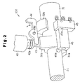
line 1C-1C in Fig. 1A; - Fig. 2 is a perspective view showing the activation restricting apparatus of Fig. 1A;
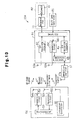
- Fig. 3 is a schematic electric block diagram of an engine starting system in the first embodiment;
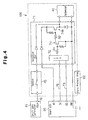
- Fig. 4 is a schematic circuit diagram of the activation restricting apparatus of Fig. 1A;
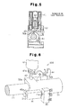
- Figs. 5 to 10 are drawings illustrating the operation of the activation restriction apparatus of Fig. 1A;
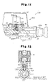
- Fig. 11 is a schematic cross-sectional view of an activation restricting apparatus of an engine starting system according to a second embodiment of the present invention;
- Fig. 12 is a cross-sectional view taken along
line 12A-12A in Fig. 11; - Fig. 13 is a schematic electric block diagram of an engine starting system in the second embodiment;
- Fig. 14 is a schematic circuit diagram of the activation restricting apparatus of Fig. 11; and
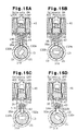
- Figs. 15A to 15D are drawings illustrating the operation of the activation restriction apparatus of Fig. 11.
-
- In the drawings, like numerals are used for like elements throughout.
- Figs. 1A to 1C are schematic cross-sectional diagrams showing an
activation restricting apparatus 100 of anengine starting system 11 according to a first embodiment of the present invention. - The
engine starting system 11 has ametal cylinder 13. Animmobilizer amplifier 17 is connected to a lower surface of thecylinder 13. Thecylinder 13 includes abore 14 and anaccommodating portion 16, which is connected with thebore 14. Acamshaft 21 is retained in thebore 14. Astarter knob 22 is connected to one end of thecamshaft 21. Thestarter knob 22 is turned between an ACC position and a LOCK position. Thestarter knob 22 includes atab 22a. Thetab 22a is used to turn thestarter knob 22. This rotates thecamshaft 21 and starts or stops the engine. In the first embodiment, thecamshaft 21 and thestarter knob 22 function as an operating means. - As shown in Fig. 2, the
camshaft 21 includes acam 31. Afirst projection 32a, which serves as a first stopper, and asecond projection 32b, which serves as a second stopper, extend from the surface of thecam 31. When thestarter knob 22 is located at the LOCK position, thefirst projection 32a restricts the movement of thestarter knob 22 to the ACC position. When thestarter knob 22 is located at positions other than the LOCK position (e.g., ACC position, ON position, or START position), thesecond projection 32b restricts the movement of thestarter knob 22 to the LOCK position. - Referring to Figs. 1A to 1C, a
solenoid 41, which serves as an actuator, is attached to thecylinder 13. Thesolenoid 41 includes aplunger 42. Astopper pin 43 is connected to theplunger 42 by adamper 42a. Thestopper pin 43 extends vertically in theaccommodating portion 16, as viewed in Figs 1A to 1C. Further, thestopper pin 43 is movable in the vertical direction. - When the
solenoid 41 is de-excited (inactivated) as shown in the state of Figs. 1A and 1B, thestopper pin 43 is projected to engage thefirst projection 32a. When thesolenoid 41 is excited (activated) as shown in the state of Fig. 1C, thestopper pin 43 is retracted and disengaged from thefirst projection 32a. Thestopper pin 43 engages thefirst projection 32a, for example, when thecamshaft 21 is arranged at the LOCK position as shown in the state of Fig. 1B. - Referring to Fig. 2, a locking lever (second stopper) 44, which serves as an intervening member, is connected to the
cylinder 13. The lockinglever 44 is pivoted about apivot pin 44a. The lockinglever 44 has a first end (left end as viewed in Fig. 2) and a second end (right end as viewed in Fig. 2). Thedamper 42a pushes the lockinglever 44 toward thefirst projection 32a. This moves the second end of the lockinglever 44 away from thesecond projection 32b. An engagingspring 47 constantly urges the second end of the lockinglever 44 toward thesecond projection 32b. Thus, a force is applied to the first end of the lockinglever 44 in a direction in which the first end disengages thefirst projection 32a. When thecamshaft 21 is in the ACC position, the lockinglever 44 engages thesecond projection 32b. - As shown in Fig. 2, the
cylinder 13 has aswitch 45, which serves as switching means. Theswitch 45 goes ON and OFF when thestarter knob 22 is turned between the LOCK position and the ACC position. Accordingly, theswitch 45 activates and inactivates thesolenoid 41. A block 46 (cooperative member) contacts or moves away from acontact 45a of theswitch 45 to activate or inactivate thesolenoid 41. In the first embodiment, when theblock 46 is in contact with thecontact 45a, theswitch 45 goes OFF and thesolenoid 41 is inactivated. When theblock 46 moves away from thecontact 45a and turns ON theswitch 45 in a state in which the shift lever of the automatic transmission for the vehicle is in the parking position, thesolenoid 41 is activated. - A spring (not shown) urges the
block 46 toward thecontact 45a of theswitch 45. Acam follower 46a projects from theblock 46 to engage acam surface 31a of thecam 31. The portion of thecam surface 31a that contacts thecam follower 46a moves in the axial direction of thestarter knob 22 in accordance with the turning of thestarter knob 22. In other words, theblock 46 moves axially in accordance with the turning of thestarter knob 22. - The electronic configuration of the
engine starting system 11 will now be discussed with reference to Figs. 3 and 4. As shown in Fig. 3, theengine starting system 11 includes aportable device 51, acommunication controller 61, thesolenoid 41, a solenoid electronic control unit (ECU) 71, aswitch 45, and ashift lock controller 81. - The
portable device 51 includes a receivingcircuit 52, amicrocomputer 53, a transmittingcircuit 54, and atransponder controller 55. The receivingcircuit 52 receives a request signal from thecommunication controller 61 and provides the request signal to themicrocomputer 53. When receiving the request signal, themicrocomputer 53 generates an ID code signal. The ID code signal includes a predetermined ID code and serves as a transmission signal. The transmittingcircuit 54 uses the ID code signal to modulate a wave having a predetermined frequency and transmits the modulated wave to an external device. The receivingcircuit 52 and the transmittingcircuit 54 are respectively connected toantennas - When the
transponder controller 55 receives sufficient energy through electromagnetic waves, thetransponder controller 55 generates a transponder signal, which includes a predetermined transponder ID code. More specifically, thetransponder controller 55 automatically generates a transponder signal having a predetermined frequency when receiving a transponder drive wave from the communication controller. Then, thetransponder controller 55 transmits the transponder signal to thecommunication controller 61. - The
communication controller 61, which is installed in the vehicle, includes a transmittingcircuit 62, afirst receiving circuit 63, asecond receiving circuit 64, a switchingcircuit 65, and asmart ECU 66. Thesmart ECU 66 serves as a control means and an ID code verification means. Thesmart ECU 66 is connected to thefirst receiving circuit 63, the transmittingcircuit 62, and thesecond receiving circuit 64. - The
first receiving circuit 63 is connected to an antenna. The transmittingcircuit 62 and thesecond receiving circuit 64 are connected to the switchingcircuit 65. The switchingcircuit 65 selectively connects theimmobilizer amplifier 17 and theantenna 17a to the transmittingcircuit 62 and thesecond receiving circuit 64. Theimmobilizer amplifier 17 amplifies the transponder signal received by theantenna 17a and provides the amplified transponder signal to thesecond receiving circuit 64. - The transmitting
circuit 62 is connected to anantenna 62a, which is installed in the passenger compartment. The transmittingcircuit 62 sends a request signal to the passenger compartment through theantenna 62a. The transmittingcircuit 62 converts the transponder signal provided from thesmart ECU 66 to a wave having a predetermined frequency and generates a transponder drive wave. The transponder drive wave is output through theantenna 17a. - The
second receiving circuit 64 receives a transponder signal from theportable device 51 through theantenna 17a. Then, thesecond receiving circuit 64 de-modulates the transponder signal to a pulse signal and generates a second receiving signal. The second receiving signal is provided to thesmart ECU 66. - The
solenoid ECU 71, which serves as a control means and an actuator drive control means, is connected to thesmart ECU 66. Thesolenoid ECU 71 is connected to thesolenoid 41 to control the activation of thesolenoid 41. Thesolenoid ECU 71, thesolenoid 41, and theswitch 45 are accommodated in alock body 12, which serves as a cover. The portion closed by thelock body 12 serves as a hard protectarea 82 in which thesolenoid ECU 71, thesolenoid 41, and theswitch 45 are protected from external impacts. - Further, referring to Fig. 4, the
shift lock controller 81, which serves as a control means, is connected to thesolenoid 41 via theswitch 45 and apower line 76. Theshift lock controller 81 detects whether the shift lever is in the parking position and whether a shift button of the shift lever is not being pressed. From the detections, theshift lock controller 81 determines whether the vehicle is not moving and inactivates thesolenoid 41 even if theswitch 45 is ON. As shown in Fig. 4, thesolenoid 41 is supplied with power from a battery via thesmart ECU 66 or theshift lock controller 81. - The
solenoid ECU 71 includes a central processing unit (CPU) 72. TheCPU 72 is connected to the base terminal of thetransistor 74 via a resistor R1. The collector terminal of thetransistor 74 is connected to the base terminal of atransistor 74a. Thetransistors solenoid 41 by thesmart ECU 66. Apower line 75 and asignal line 73 connect theCPU 72 and thesmart ECU 66 to each other. Power is supplied to theCPU 72 through thepower line 75. Thesignal line 73 us used for serial communication to send information from thesmart ECU 66 to theCPU 72 on whether encoded ID codes are matched. - The
smart ECU 66, which includes a CPU, a ROM, and a RAM (none of which are shown), intermittently generates a request signal. Thesmart ECU 66 has a predetermined ID code and compares its ID code with an ID code included in the first receiving signal or the second receiving signal when receiving the first or second receiving signal. When the ID codes match, thesmart ECU 66 generates an activation signal and provides the activation signal to theCPU 72. Then, theCPU 72 provides thetransistor 74 with the activation signal to activate thesolenoid 41. - More specifically, if the
portable device 51 generates an ID code signal in response to a request signal output from theantenna 62a when thestarter knob 22 is in the LOCK position, thesmart ECU 66 determines that theportable device 51 is located in the passenger compartment and activates thesolenoid 41 for five seconds. Theportable device 51 is inserted in thetab 22a, as shown in Fig. 1A, when the power of theportable device 51 weakens or when one does not know how to operate thestarter knob 22. In this state, as long as theportable device 51 generates the transponder signal in response to a transponder drive wave, thesmart ECU 66 activates thesolenoid 41 for five seconds. - As a result, as shown in Fig. 5, the
plunger 42 moves and disengages thestopper pin 43 from thefirst projection 32a to enable the turning of the starter knob. In this state, after pushing thestarter knob 22 in the axial direction, thestarter knob 22 is turned to move thestarter knob 22 from the LOCK position to the ACC position. Then, when the output of the activation signal from thesmart ECU 66 ends, thesmart ECU 66 and the solenoid ECU are inactivated. In this state, the turning of thestarter knob 22 moves theblock 46 away from thecontact 45a and turns ON theswitch 45, as shown in the state of Fig. 6. Since the shift lever is arranged at the parking position, thesolenoid 41 returns to the inactivated state, and thestopper pin 43 projects into thebore 14. - The
starter knob 22 is pushed in the axial direction, for example, when a driver does not immediately start the engine after getting into the vehicle to again request ID code verification and to enable the turning of thestarter knob 22. Since the rotation of thecamshaft 21 from the ACC position to the START position is enabled as shown in the state of Fig. 8, the engine may be started by activating a starting relay (not shown) to drive a starting motor (not shown). Accordingly, theengine starting system 11 functions as a smart ignition apparatus. - If the shift lever is moved from the parking position to another position when the engine is running, this activates the
solenoid 41 and moves theplunger 42 upward, as shown in the state of Fig. 9. Simultaneously, the force of the engaging spring 47 (Fig. 1A) pivots the lockinglever 44 so that the lockinglever 44 engages thesecond projection 32b. Therefore, if the driver stops the engine and tries to turn thestarter knob 22 in the direction indicated by arrow F1 to the LOCK position when the shift lever is located at a position other than the parking position, the engagement between the lockinglever 44 and thesecond projection 32b prohibits the turning of thestarter knob 22. - The
shift lock controller 81 detects whether the vehicle is not moving when thestarter knob 22 is located at the ACC position. In this state, thesolenoid 41 is not activated even if theswitch 45 is ON since theshift lock controller 81 does not supply thesolenoid 41 with power. Thus, as shown in the state of Fig. 10, theplunger 42 moves downward and disengages the lockinglever 44 from thesecond projection 32b to enable the turning of thestarter knob 22. By turning thestarter knob 22 in this state, the first projection lifts thestopper pin 43 until thestarter knob 22 reaches the LOCK position. Then, as shown in the state of Fig. 2, theblock 46 contacts thecontact 45a and turns on theswitch 45. Further, the engagement between thestopper pin 43 and thefirst projection 32a prohibits the turning of thestarter knob 22. Accordingly, theengine starting system 11 functions as a key interlocking mechanism. - The engine starting system
activation restricting apparatus 100 of the first embodiment has the advantages described below. - (1) The
solenoid 41 enables the starting of the engine with thestarter knob 22 when thecamshaft 21 is located at the LOCK position. Further, thesolenoid 41 disengages the lockinglever 44 from thesecond projection 32b when thestarter knob 22 is located at a position other than the LOCK position as long as theswitch 45 activates thesolenoid 41 and the vehicle is not moving. This enables thestarter knob 22 to be turned to the LOCK position. Thus, thesame solenoid 41 is used to enable the turning of thestarter knob 22 regardless of whether thestarter knob 22 is located at the LOCK position or the ACC position. Thus, thesolenoid 41 does not occupy much space. This enables theengine starting system 11 to be produced more compactly and improves safety with respect to collisions. - Even when adding a smart ignition apparatus to a vehicle, the
engine starting system 11 requires only onesolenoid 41. Thus, thesame lock body 12, which accommodates theengine starting system 11, may be used even when adding the smart ignition apparatus. This decreases the cost of theengine starting system 11. - (2) The activation and inactivation of the solenoid41 are performed mechanically by moving the
block 46 toward or away from the block. More specifically, thesolenoid 41 is inactivated when theblock 46 contacts thecontact 45a. Thesolenoid 41 is activated when theblock 46 moves away from thecontact 45a. This guarantees that the movement of theswitch 45 is enabled. - (3) When the vehicle has an automatic transmission, it can be confirmed that the vehicle is not moving by checking whether the shift lever is located at the parking position. In addition, it can be confirmed that the vehicle is not moving by checking whether the shift button of the shift lever is not being pressed. When it is detected that the vehicle is not moving, the turning of the
starter knob 22 to the LOCK position is enabled. In other words, the turning of thestarter knob 22 to the LOCK position is prohibited when the vehicle is moving. This improves the safety of the vehicle. - (4) The
stopper pin 43 of thesolenoid 41 engages thefirst projection 32a when thesolenoid 41 is inactivated. Thus, when the battery goes dead, thestopper pin 43 is not disengaged from thefirst projection 32a, and thestarter knob 22 thus cannot be turned. This improves the security of the vehicle with respect to thefts. - (5) The
switch 45 is arranged in thelock body 12. Thus, current does not flow directly to thesolenoid 41 even if, for example, a thief intentionally sends current through thepower line 76 as long as theswitch 45 is OFF. In addition, thesolenoid ECU 71, which includes thesolenoid 41 and theCPU 72, is located in thelock body 12. Thus, current does not flow directly to thetransistor 74 even if, for example, a thief intentionally sends current through thepower line 75. This prevents thesolenoid 41 from being improperly driven to turn thestarter knob 22. Accordingly, the engine is prevented from being started by an unauthorized person. This further improves the security of the vehicle with respect to thefts. - (6) The
smart ECU 66 and thesolenoid ECU 71 are activated only when thestarter knob 22 is turned from the LOCK position to the ACC position. Thus, thesmart ECU 66 and thesolenoid ECU 71 are inactivated when thesmart ECU 66 stops outputting the activation signal. This decreases the current consumed by theengine starting system 11. - (7) The
starter knob 22 may be pushed along its axial direction. The time lag that occurs when activating the solenoid 41 (i.e., the time required to activated the solenoid 41) is absorbed during the period in which thestarter knob 22 is pushed. This guarantees engagement between thestopper pin 43 and thefirst projection 32a. Accordingly, thestarter knob 22 is prevented from being interfered with by thestopper pin 43. - Fig. 11 is a cross-sectional view of an engine starting system
activation restricting apparatus 200 according to a second embodiment of the present invention. Fig. 12 is a schematic cross-sectional view taken along line 12-12. Parts differing from the first embodiment will now be described. Identical parts will not be described. - Referring to Fig. 12, a
cam 31A has a first recess (first stopper) 132a and a second recess (second stopper) 132b in lieu of the first andsecond projections activation restricting apparatus 200 does not have the lockinglever 44 and theswitch 45 of the first embodiment. - As shown in Fig. 11, in the second embodiment, an
engine starting system 11A includes acylinder 13, which has an attachingportion 15 and anaccommodating portion 16. Theaccommodating portion 16 is connected to abore 14 through aplunger insertion hole 16a. Astopper pin 43 extends vertically through theaccommodating portion 16. Aspring 144 urges thestopper pin 43 upward, as viewed in Fig. 12. - As shown in Fig. 12, the first and
second recesses cam 31A. The dimension of thesecond recess 132b in the circumferential direction of thecam 31A is greater than that of thefirst recess 132a. Thefirst recess 132a corresponds to the LOCK position of astarter knob 22. Thesecond recess 132b corresponds to positions of thestarter knob 22 other than the LOCK position (i.e., ACC position, ON position, and START position). - The
stopper pin 43 is engaged with and disengaged from thefirst recess 132a or thesecond recess 132b by thesolenoid 41. More specifically, when thesolenoid 41 is inactivated, thestopper pin 43 is held in a state engaged with thefirst recess 132a or thesecond recess 132b. When thesolenoid 41 is activated, thestopper pin 43 is disengaged from thefirst recess 132a or thesecond recess 132b. When acamshaft 21 is located at a position corresponding to the LOCK position, thestopper pin 43 engages thefirst recess 132a. As shown in the state of Fig. 15C, when thecamshaft 21 is located at the ACC position, thestopper pin 43 engages thesecond recess 132b. - The electronic configuration of the
engine starting system 11A will now be discussed with reference to Figs. 13 and 14. - Referring to Fig. 13, the
portable device 51 includes a receiving circuit, amicrocomputer 53, a transmittingcircuit 54, and atransponder controller 55. Thecommunication controller 61, which is installed in a vehicle, includes a transmittingcircuit 62, afirst receiving circuit 63, asecond receiving circuit 64, a switchingcircuit 65, and asmart ECU 66, which serves as a control means. - In the second embodiment, a
shift lock controller 81, which serves as a control means, is connected to thesmart ECU 66. Theshift lock controller 81 detects whether a shift lever of the automatic transmission for the vehicle is in the parking position and whether a shift button arranged on the shift lever is not being pressed. From the detections, theshift lock controller 81 determines whether the vehicle is not moving and generates a vehicle stop signal. The vehicle stop signal is provided to thesmart ECU 66. - The
smart ECU 66 us connected to asolenoid ECU 71A, which controls the activation of thesolenoid 41. Referring to Fig. 14, thesmart ECU 66 supplies thesolenoid 41 with power. Thesolenoid ECU 71A includes aCPU 72. TheCPU 72 is connected to the base terminal of atransistor 74 via a resistor R1. - If the
portable device 51 generates an ID code signal in response to a request signal output from anantenna 62a when thestarter knob 22 is in the LOCK position, thesmart ECU 66 determines that theportable device 51 is located in the passenger compartment and activates thesolenoid 41 for five seconds. - This moves the
plunger 42 and disengages thestopper pin 43 from thefirst recess 132a to enable turning of thestarter knob 22, as shown in the state of Fig. 15A. In this state, by pushing thestarter knob 22 in the axial direction and then rotating thestarter knob 22, thestarter knob 22 is moved to the ACC position, as shown in the state of Fig. 15B. Then, thesolenoid 41 is inactivated so that thestopper pin 43 engages thesecond recess 132b. - In the states of Figs. 15C and 15D, the turning of the
starter knob 22 from the ACC position to the START position is enabled. Thus, the engine may be started by activating a starting relay (not shown) to drive a starting motor (not shown). Accordingly, theengine starting system 11A functions as a smart ignition apparatus. - The
solenoid ECU 71A activates thesolenoid 41 when thestarter knob 22 is located at the ACC position as long as the vehicle is not moving. More specifically, theCPU 72 generates an activation signal in accordance with a vehicle stop signal from theshift lock controller 81 and provides thetransistor 74 with the activation signal. Thetransistor 74 activates thesolenoid 41 in response to the activation signal. This moves theplunger 42 and disengages thestopper pin 43 from thesecond recess 132b to enable turning of thestarter knob 22. From this state, thestarter knob 22 is pushed in the axial direction and then turned to the LOCK position. Subsequently, thesolenoid 41 is inactivated. This engages thestopper pin 43 with thefirst recess 132a and prohibits turning of thestarter knob 22, as shown in the state of Fig. 12. Accordingly, theengine starting system 11A functions as a key interlocking mechanism. - The engine starting system
activation restricting apparatus 200 of the second embodiment has the same advantages as those of the first embodiment. - It should be apparent to those skilled in the art that the present invention may be embodied in many other specific forms. Particularly, it should be understood that the present invention may be embodied in the following forms.
- In each of the above embodiments, the determination that the vehicle is not moving may be performed based on only one of the conditions of whether the shift lever is in the parking position and whether the shift button is being pressed. Further, other conditions may be used to detect that the vehicle is not moving. For example, if a vehicle velocity sensor detects that the vehicle velocity is 0 Km/h, it may be determined that the vehicle is not moving.
- In each of the above embodiments, the
solenoid 41 may be replaced by a motor that serves as an actuator. In such a case, the motor has a shaft to which a pinion gear is attached. A rack gear, which is meshed with the pinion gear, is attached to thestopper pin 43 along the longitudinal direction of thestopper pin 43. The motor is driven to move thestopper pin 43. - In each of the embodiments, the
starter knob 22 may be pulled along its axial direction. - In the first embodiment, the
stopper pin 43 may be held in a state engaged with thefirst projection 32a when thesolenoid 41 is activated and disengaged from thefirst projection 32a when thesolenoid 41 is inactivated. In this case, theshift lock controller 81 activates thesolenoid 41 when detecting that the vehicle is not moving. - In the first embodiment, the
smart ECU 66 and thesolenoid ECU 71 may remain activated even after thestarter knob 22 is turned to the ACC position from the LOCK position. - In the second embodiment, the
stopper pin 43 may be held in a state engaged with thefirst recess 132a or thesecond recess 132b when thesolenoid 41 is activated and disengaged from thefirst recess 132a or thesecond recess 132b when thesolenoid 41 is inactivated. - The present examples and embodiments are to be considered as illustrative and not restrictive.
Claims (17)
- An apparatus for restricting activation of a starting system of an engine of a vehicle and for use with a portable device that transmits a first ID code, the apparatus including an operating means (21, 22) for manually starting and stopping the engine and having a plurality of operation positions including a LOCK position in which the operating means is locked, the operating means including a first stopper (32a; 132a), which prohibits movement of the operating means from the LOCK position to a position other than the LOCK position, and a second stopper (32b, 44; 132b), which prohibits movement of the operating means to the LOCK position from a position other than the LOCK position, an actuator (41) for engaging the first and second stoppers, and a control means (66, 71, 81) connected to the actuator to control the actuator, the apparatus being characterized in that:the control means enables the engine to be started by disengaging the actuator from the first stopper when the operating means is in the LOCK position and the first ID code sent from the portable device matches a predetermined second ID code of the control means, and wherein the control means enables the operating means to be moved to the LOCK position by disengaging the actuator from the second stopper when the operating means is in a position other than the LOCK position and the vehicle is not moving.
- The apparatus according to claim 1, further characterized by:wherein the first stopper includes a first projection (32a) engaged with the actuator;a switching means (45) for activating the actuator when the operating means is in a position other than the LOCK position;
the second stopper includes a second projection (32b) and an intervening member (44), which is arranged between the actuator and the second projection to engage the second projection in cooperation with the actuator; and
the control means enables the operating means to be moved to the LOCK position by inactivating the actuator to disengage the intervening member from the second projection when the operating means is in a position other than the LOCK position, the actuator is activated by the switching means, and the vehicle is not moving. - The apparatus according to claim 2, characterized in that the vehicle includes electric devices, and the control means includes:wherein the plurality of operation positions include an ACC position in which electric devices of the vehicle are supplied with power; andan ID code verification means (66) for determining whether the first ID code matches the second ID code; andan actuator control means (71) for controlling the actuator;
the ID code verification means and the actuator control means are inactivated when the operating means is moved from the LOCK position to the ACC position. - The apparatus according to claim 3, characterized in that the operating means includes a knob (22) turned about its axis to move the operating means between the ACC position and the LOCK position, the knob being movable in its axial direction, and wherein the switching means is mechanically activated, the apparatus further comprising:a cooperative member (46) for mechanically activating the switching means by moving toward and away from the switching means when the operating means is turned.
- The apparatus according to claim 3, further characterized by:a cover (12) for covering the actuator, the actuator control means, and the switching means.
- The apparatus according to claim 2, characterized in that the vehicle includes an automatic transmission having a shift lever shiftable to a plurality of positions, including a parking position, and the control means determines that the vehicle is not moving when the shift lever is in the parking position.
- The apparatus according to claim 6, characterized in that the shift lever has a button for shifting the shift lever between different positions, and the control means determines that the vehicle is not moving when the shift lever is in the parking position and the button is not being pressed.
- The apparatus according to claim 2, characterized in that the actuator is a solenoid (41) including a stopper pin (43) engaged with the first projection when the solenoid is inactivated and disengaged from the first projection when the solenoid is activated.
- The apparatus according to claim 1, characterized in that:the first stopper includes a first recess (132a) engaged with the actuator;the second stopper includes a second recess (132b)the actuator engages with the first recess and the second recess; andthe control means enables the operating means to be moved to the LOCK position by activating the actuator to disengage the actuator from the second recess when the operating means is in a position other than the LOCK position and the vehicle is not moving.
- The apparatus according to claim 9, characterized in that the vehicle includes electric devices and the plurality of operation positions include an ACC position in which electric devices of the vehicle are supplied with power, and the operating means includes a knob (22) turned about its axis to move the operating means between the ACC position and the LOCK position, the knob being movable in its axial direction.
- The apparatus according to claim 9, further characterized by:an actuator control means (71A) for controlling the actuator; anda cover (12) for covering the actuator and the actuator control means.
- The apparatus according to claim 9, characterized in that the vehicle includes an automatic transmission having a shift lever shiftable to a plurality of positions, including a parking position, and the control means determines that the vehicle is not moving when the shift lever is in the parking position.
- The apparatus according to claim 12, characterized in that the shift lever has a button for shifting the shift lever between different positions, and the control means determines that the vehicle is not moving when the shift lever is in the parking position and the button is not being pressed.
- The apparatus according to claim 9, characterized in that the actuator is a solenoid (41) including a stopper pin (43) engaged with the first recess when the solenoid is inactivated and disengaged from the first projection when the solenoid is activated.
- An apparatus for restricting activation of a starting system of an engine of a vehicle and for use with a portable device operable for sending a first ID code, the apparatus including an operating means (21, 22) for manually starting and stopping the engine and having a plurality of operation positions including a LOCK position in which the operating means is locked, the operating means including a first projection (32a), which prohibits movement of the operating means from the LOCK position to a position other than the LOCK position, and a second projection (32b), which prohibits movement of the operating means to the LOCK position from a position other than the LOCK position, an actuator (41) for engaging the first and second stoppers, an intervening member (44) arranged between the actuator and the second projection to engage the second projection in cooperation with the actuator, an actuator control means (71) connected to the actuator to control the actuator, and an ID code verification means (66) connected to the actuator control means to determine whether the first ID code when sent from the portable device matches a second ID code, the apparatus being characterized by:wherein the actuator control means enables the engine to be started by disengaging the actuator from the first projection when the operating means is in the LOCK position and the first ID code matches the second ID code.a shift lock control means (81) connected to the actuator for enabling the operating means to be moved to the LOCK position by disengaging the intervening member from the second projection when the operating means is in a position other than the LOCK position and the vehicle is not moving;
- The apparatus according to claim 15, further characterized by:wherein the ID code verification means and the actuator control means are inactivated when the operating means is moved from the LOCK position to a position other than the LOCK position.a switching means (45) for connecting the shift lock control means to the actuator when the operating means is in a position other than the LOCK position;
- The apparatus according to claim 15, characterized in that the vehicle includes electric devices and the plurality of operating positions include an ACC position in which electric devices of the vehicle are supplied with power and an ON position in which the engine is driven.
Applications Claiming Priority (4)
| Application Number | Priority Date | Filing Date | Title |
|---|---|---|---|
| JP2002156193 | 2002-05-29 | ||
| JP2002156194 | 2002-05-29 | ||
| JP2002156194A JP3878515B2 (en) | 2002-05-29 | 2002-05-29 | Engine starter operation restriction mechanism |
| JP2002156193A JP3908089B2 (en) | 2002-05-29 | 2002-05-29 | Operation restriction device for engine starting system |
Publications (3)
| Publication Number | Publication Date |
|---|---|
| EP1378406A2 true EP1378406A2 (en) | 2004-01-07 |
| EP1378406A3 EP1378406A3 (en) | 2004-10-20 |
| EP1378406B1 EP1378406B1 (en) | 2006-09-06 |
Family
ID=29720902
Family Applications (1)
| Application Number | Title | Priority Date | Filing Date |
|---|---|---|---|
| EP20030445064 Expired - Lifetime EP1378406B1 (en) | 2002-05-29 | 2003-05-28 | Apparatus for restricting activation of engine starting system |
Country Status (5)
| Country | Link |
|---|---|
| US (2) | US7302817B2 (en) |
| EP (1) | EP1378406B1 (en) |
| KR (1) | KR100864033B1 (en) |
| CN (1) | CN100339256C (en) |
| DE (1) | DE60308101T2 (en) |
Cited By (1)
| Publication number | Priority date | Publication date | Assignee | Title |
|---|---|---|---|---|
| WO2015181400A1 (en) * | 2014-05-30 | 2015-12-03 | Huf Hülsbeck & Fürst Gmbh & Co. Kg | Lock cylinder having a resetting block |
Families Citing this family (41)
| Publication number | Priority date | Publication date | Assignee | Title |
|---|---|---|---|---|
| DE10018727A1 (en) * | 2000-04-15 | 2001-10-18 | Bayerische Motoren Werke Ag | Remote-controlled ignition steering lock for motorcycles |
| DE10147031B4 (en) * | 2000-09-27 | 2012-11-29 | Marquardt Gmbh | Ignition lock for a motor vehicle |
| JP2002308049A (en) * | 2001-04-11 | 2002-10-23 | Tokai Rika Co Ltd | Engine starting device for vehicle |
| DE60308101T2 (en) * | 2002-05-29 | 2007-05-10 | Kabushiki Kaisha Tokai Rika Denki Seisakusho | Device for preventing the activation of an engine starting system |
| US6941779B2 (en) * | 2002-07-30 | 2005-09-13 | Kabushiki Kaisha Honda Lock | Steerage locking system for vehicle |
| JP3990224B2 (en) * | 2002-08-09 | 2007-10-10 | 株式会社ホンダロック | Steering lock device |
| JP4100570B2 (en) * | 2003-10-03 | 2008-06-11 | 本田技研工業株式会社 | Vehicle locking device |
| US7140213B2 (en) * | 2004-02-21 | 2006-11-28 | Strattec Security Corporation | Steering column lock apparatus and method |
| DE102004019919B3 (en) * | 2004-04-21 | 2006-02-02 | Huf Hülsbeck & Fürst Gmbh & Co. Kg | Device for starting a vehicle engine by means of an electronic key and a key to be used for this purpose |
| DE102005002018A1 (en) * | 2005-01-15 | 2006-07-20 | Marquardt Gmbh | Ignition lock for motor vehicle has locking element in first position of which movement of motion element is prevented by complete guidance of key and it allows second release position by reaching extreme position of teeth of key |
| US20060220458A1 (en) * | 2005-04-05 | 2006-10-05 | Feldman Mark G | Keyless ignition module for an automotive vehicle |
| KR100851139B1 (en) * | 2005-12-09 | 2008-08-08 | 현대자동차주식회사 | Key Interlock Device for Steering Column Lock Device |
| US7730752B2 (en) * | 2006-03-13 | 2010-06-08 | Kawasaki Jukogyo Kabushiki Kaisha | Theft prevention apparatus for leisure vehicle |
| US20090199604A1 (en) * | 2006-06-07 | 2009-08-13 | Eung Lyul Kim | Steering lock device for coupling electronic identification system and method of manufacturing thereof |
| WO2008137575A1 (en) * | 2007-05-03 | 2008-11-13 | Jonathon Hocut | Bump resistant pin tumbler lock |
| KR100820859B1 (en) * | 2007-07-31 | 2008-04-11 | 양재우 | Electronic key structure for vehicle security |
| KR100921048B1 (en) * | 2007-12-15 | 2009-10-08 | 현대자동차주식회사 | Shift lever lock on vehicle equipped with smart key system |
| JP5038238B2 (en) * | 2008-06-12 | 2012-10-03 | 株式会社東海理化電機製作所 | Vehicle function restriction system |
| JP5296470B2 (en) * | 2008-09-24 | 2013-09-25 | 株式会社東海理化電機製作所 | In-vehicle auxiliary key key holding device |
| KR100986462B1 (en) * | 2008-11-28 | 2010-10-08 | 기아자동차주식회사 | Key interlock of the car |
| JP5118078B2 (en) * | 2009-02-03 | 2013-01-16 | 株式会社東海理化電機製作所 | Key control device |
| JP5118079B2 (en) * | 2009-02-03 | 2013-01-16 | 株式会社東海理化電機製作所 | Key device |
| KR101094910B1 (en) * | 2009-10-30 | 2011-12-16 | 기아자동차주식회사 | Key Interlock Device for Vehicle |
| JP5394981B2 (en) * | 2010-05-13 | 2014-01-22 | 株式会社東海理化電機製作所 | Ignition switch operation restriction device |
| JP5431250B2 (en) * | 2010-06-08 | 2014-03-05 | 株式会社東海理化電機製作所 | Key interlock device |
| FR2965230B1 (en) * | 2010-09-28 | 2020-02-28 | U-Shin France Sas | STEERING LOCK FOR MOTOR VEHICLE |
| JP5611752B2 (en) * | 2010-10-07 | 2014-10-22 | 株式会社東海理化電機製作所 | Ignition switch operation restriction device |
| US8587147B2 (en) | 2012-02-17 | 2013-11-19 | Johnson Industries, Inc. | Safety system |
| US9261234B2 (en) | 2012-02-17 | 2016-02-16 | Johnson Industries, Inc. | Safety system |
| CN102797842A (en) * | 2012-08-30 | 2012-11-28 | 黄山市汽车电器股份公司 | Anti-misoperation structure for ignition switch |
| DE202013009915U1 (en) * | 2012-12-03 | 2014-05-13 | Strattec Security Corporation | Ignition lock steering column lock assembly |
| CN103935322A (en) * | 2013-01-23 | 2014-07-23 | 长春易控汽车电子有限公司 | Automobile password anti-theft method |
| FR3007571B1 (en) * | 2013-06-20 | 2015-06-19 | Shin France U | ELECTROMECHANICAL ACTUATOR AND METHOD OF USING THE ELECTROMECHANICAL ACTUATOR |
| LU92228B1 (en) * | 2013-06-20 | 2014-12-22 | Iee Sarl | Heatable interior trim element |
| FR3012094B1 (en) * | 2013-10-21 | 2016-01-01 | Shin France U | ANTI-THEFT FOR THE STEERING COLUMN OF A MOTOR VEHICLE |
| JP6042459B2 (en) * | 2015-01-07 | 2016-12-14 | 株式会社東海理化電機製作所 | Key cylinder device |
| JP6471105B2 (en) * | 2016-01-14 | 2019-02-13 | 株式会社東海理化電機製作所 | Steering lock device and method of assembling steering locking device |
| JP6166427B1 (en) * | 2016-06-02 | 2017-07-19 | 株式会社東海理化電機製作所 | Steering lock device |
| JP6851044B2 (en) * | 2016-12-22 | 2021-03-31 | 朝日電装株式会社 | Engine starter |
| EP3339110B1 (en) * | 2016-12-22 | 2020-02-05 | Asahi Denso Co., Ltd. | Engine starting device |
| US10501050B2 (en) * | 2017-06-30 | 2019-12-10 | GM Global Technology Operations LLC | Vehicle ignition system |
Family Cites Families (30)
| Publication number | Priority date | Publication date | Assignee | Title |
|---|---|---|---|---|
| FR2288651A1 (en) * | 1974-03-05 | 1976-05-21 | Neiman Exploit Des Brevets | SAFETY ANTI-THEFT DEVICE FOR VEHICLES EQUIPPED WITH A DIESEL ENGINE |
| JPS5825759A (en) | 1981-08-07 | 1983-02-16 | Hitachi Ltd | Two-dimensional encoding K value automatic switching method |
| JPS5871236A (en) | 1981-10-22 | 1983-04-27 | Toyota Motor Corp | Ignition switch device for car |
| FR2569641B1 (en) * | 1984-08-31 | 1991-05-03 | Kiekert Gmbh Co Kg | SAFETY DEVICE AGAINST UNAUTHORIZED USE OF A MOTOR VEHICLE |
| JP2685185B2 (en) * | 1987-07-21 | 1997-12-03 | 日産自動車株式会社 | Steering lock device |
| DE4019478A1 (en) * | 1989-06-20 | 1991-01-10 | Honda Motor Co Ltd | ELECTRIC POWER SUPPLY CONTROL UNIT FOR A MOTOR VEHICLE |
| DE4037918C1 (en) * | 1990-11-29 | 1991-11-07 | Bayerische Motoren Werke Ag, 8000 Muenchen, De | Vehicle steering-ignition lock - has stop fixed to key cylinder which contacts lock element to prevent movement unless operated by correct key |
| US5685183A (en) * | 1994-07-19 | 1997-11-11 | Kabushiki Kaisha Tokai Rika Denki Seisakusho | Vehicle locking device |
| DE69623527T2 (en) * | 1995-04-11 | 2003-05-22 | Tokai Rika Co., Ltd. | Start control for vehicles |
| JP3580923B2 (en) * | 1995-12-21 | 2004-10-27 | 株式会社日本自動車部品総合研究所 | Anti-theft device |
| JP3708296B2 (en) * | 1996-08-09 | 2005-10-19 | 万能工業株式会社 | Shift lock mechanism for shift lever device for column AT |
| JPH10236280A (en) | 1997-03-03 | 1998-09-08 | Yazaki Corp | IC card for vehicle, ignition switch device using IC card, and steering lock device |
| JPH10315914A (en) * | 1997-05-19 | 1998-12-02 | Tokai Rika Co Ltd | Starting device for vehicles |
| JP3142508B2 (en) | 1997-07-23 | 2001-03-07 | トヨタ自動車株式会社 | Vehicle electronic key device |
| AU7628398A (en) * | 1997-09-12 | 1999-03-25 | Robert Bosch Gmbh | An ignition lock system |
| DE19821899C2 (en) * | 1998-05-15 | 2001-06-13 | Siemens Ag | Rotary switch, in particular ignition starter switch |
| JP3657137B2 (en) | 1999-02-05 | 2005-06-08 | 富士重工業株式会社 | Engine starter |
| JP4028117B2 (en) | 1999-02-09 | 2007-12-26 | 株式会社東海理化電機製作所 | Key lock device |
| JP3688923B2 (en) * | 1999-02-09 | 2005-08-31 | 株式会社東海理化電機製作所 | Shift lever device |
| JP3938822B2 (en) * | 1999-07-07 | 2007-06-27 | 株式会社東海理化電機製作所 | Shift lever device |
| DE19942485A1 (en) * | 1999-09-07 | 2001-04-05 | Bosch Gmbh Robert | Motor vehicle door locking system with passive entry function and quick release |
| DE19951986C1 (en) * | 1999-10-28 | 2001-08-09 | Huf Huelsbeck & Fuerst Gmbh | Electronic ignition starter switch for motor vehicles |
| JP3924416B2 (en) | 2000-04-25 | 2007-06-06 | 株式会社東海理化電機製作所 | Engine starter for vehicle |
| DE10126129B4 (en) * | 2000-05-31 | 2011-06-01 | Kabushiki Kaisha Tokai Rika Denki Seisakusho | Switchgear for vehicles |
| JP2002067880A (en) * | 2000-08-31 | 2002-03-08 | Tokai Rika Co Ltd | Emergency release structure for interlock |
| US6516640B2 (en) * | 2000-12-05 | 2003-02-11 | Strattec Security Corporation | Steering column lock apparatus and method |
| JP3851803B2 (en) * | 2001-02-09 | 2006-11-29 | 株式会社東海理化電機製作所 | Electronic vehicle anti-theft device |
| JP2002308049A (en) * | 2001-04-11 | 2002-10-23 | Tokai Rika Co Ltd | Engine starting device for vehicle |
| JP3838630B2 (en) * | 2002-02-27 | 2006-10-25 | 株式会社ホンダロック | Engine starter for vehicle |
| DE60308101T2 (en) * | 2002-05-29 | 2007-05-10 | Kabushiki Kaisha Tokai Rika Denki Seisakusho | Device for preventing the activation of an engine starting system |
-
2003
- 2003-05-28 DE DE2003608101 patent/DE60308101T2/en not_active Expired - Lifetime
- 2003-05-28 US US10/446,469 patent/US7302817B2/en not_active Expired - Fee Related
- 2003-05-28 EP EP20030445064 patent/EP1378406B1/en not_active Expired - Lifetime
- 2003-05-28 KR KR1020030034174A patent/KR100864033B1/en not_active Expired - Fee Related
- 2003-05-29 CN CNB031406351A patent/CN100339256C/en not_active Expired - Fee Related
-
2007
- 2007-06-22 US US11/767,133 patent/US20080041128A1/en not_active Abandoned
Non-Patent Citations (1)
| Title |
|---|
| None |
Cited By (2)
| Publication number | Priority date | Publication date | Assignee | Title |
|---|---|---|---|---|
| WO2015181400A1 (en) * | 2014-05-30 | 2015-12-03 | Huf Hülsbeck & Fürst Gmbh & Co. Kg | Lock cylinder having a resetting block |
| US10414375B2 (en) | 2014-05-30 | 2019-09-17 | Huf Hülsbeck & Fürst Gmbh & Co. Kg | Lock cylinder having a resetting block |
Also Published As
| Publication number | Publication date |
|---|---|
| DE60308101D1 (en) | 2006-10-19 |
| KR100864033B1 (en) | 2008-10-16 |
| US7302817B2 (en) | 2007-12-04 |
| CN100339256C (en) | 2007-09-26 |
| DE60308101T2 (en) | 2007-05-10 |
| US20040003632A1 (en) | 2004-01-08 |
| KR20030093124A (en) | 2003-12-06 |
| EP1378406B1 (en) | 2006-09-06 |
| EP1378406A3 (en) | 2004-10-20 |
| US20080041128A1 (en) | 2008-02-21 |
| CN1478683A (en) | 2004-03-03 |
Similar Documents
| Publication | Publication Date | Title |
|---|---|---|
| EP1378406B1 (en) | Apparatus for restricting activation of engine starting system | |
| EP1445158B1 (en) | Engine switch device | |
| US7591158B2 (en) | Vehicle locking apparatus | |
| US6756698B2 (en) | Switch device for vehicle | |
| US20060236970A1 (en) | Control system for vehicle | |
| US7199710B2 (en) | Controller for remote control system | |
| JP2009143528A (en) | Shift lever locking device for vehicle | |
| US6380642B1 (en) | Method for starting a motor vehicle and ignition-starter device | |
| US20020023809A1 (en) | Electronic control unit and method for the automatic activation of the parking brake in motor vehicles | |
| US7501714B2 (en) | Engine starting system | |
| US7011377B2 (en) | Electronic control unit for automatically activating a parking brake and method for preventing the automatic activation of the parking brake in motor vehicles | |
| JP3885022B2 (en) | Vehicle antitheft device | |
| JP4144741B2 (en) | Vehicle anti-theft device | |
| JP2009293389A (en) | Engine starting device | |
| US7564146B2 (en) | Moving body starting system | |
| JP3878515B2 (en) | Engine starter operation restriction mechanism | |
| CN100464065C (en) | Engine start/stop control system | |
| JP2003341477A (en) | Operation restricting device of engine starting system | |
| EP0893316B1 (en) | Car theft preventive apparatus | |
| JP4199582B2 (en) | Electronic steering lock device | |
| JP4056422B2 (en) | Steering lock device safety device | |
| JP3379888B2 (en) | Vehicle anti-theft device | |
| JP6533152B2 (en) | Steering lock device | |
| JP2676411B2 (en) | Handle lock device and engine ignition device | |
| US11312330B1 (en) | System and method for keyless operation of vehicle ignition |
Legal Events
| Date | Code | Title | Description |
|---|---|---|---|
| PUAI | Public reference made under article 153(3) epc to a published international application that has entered the european phase |
Free format text: ORIGINAL CODE: 0009012 |
|
| AK | Designated contracting states |
Kind code of ref document: A2 Designated state(s): AT BE BG CH CY CZ DE DK EE ES FI FR GB GR HU IE IT LI LU MC NL PT RO SE SI SK TR |
|
| AX | Request for extension of the european patent |
Extension state: AL LT LV MK |
|
| PUAL | Search report despatched |
Free format text: ORIGINAL CODE: 0009013 |
|
| AK | Designated contracting states |
Kind code of ref document: A3 Designated state(s): AT BE BG CH CY CZ DE DK EE ES FI FR GB GR HU IE IT LI LU MC NL PT RO SE SI SK TR |
|
| AX | Request for extension of the european patent |
Extension state: AL LT LV MK |
|
| RIC1 | Information provided on ipc code assigned before grant |
Ipc: 7B 60R 25/02 B Ipc: 7B 60R 25/04 A |
|
| 17P | Request for examination filed |
Effective date: 20041126 |
|
| 17Q | First examination report despatched |
Effective date: 20050318 |
|
| AKX | Designation fees paid |
Designated state(s): DE FR GB SE |
|
| GRAP | Despatch of communication of intention to grant a patent |
Free format text: ORIGINAL CODE: EPIDOSNIGR1 |
|
| GRAS | Grant fee paid |
Free format text: ORIGINAL CODE: EPIDOSNIGR3 |
|
| GRAA | (expected) grant |
Free format text: ORIGINAL CODE: 0009210 |
|
| AK | Designated contracting states |
Kind code of ref document: B1 Designated state(s): DE FR GB SE |
|
| REG | Reference to a national code |
Ref country code: GB Ref legal event code: FG4D |
|
| REF | Corresponds to: |
Ref document number: 60308101 Country of ref document: DE Date of ref document: 20061019 Kind code of ref document: P |
|
| REG | Reference to a national code |
Ref country code: SE Ref legal event code: TRGR |
|
| ET | Fr: translation filed | ||
| PLBE | No opposition filed within time limit |
Free format text: ORIGINAL CODE: 0009261 |
|
| STAA | Information on the status of an ep patent application or granted ep patent |
Free format text: STATUS: NO OPPOSITION FILED WITHIN TIME LIMIT |
|
| 26N | No opposition filed |
Effective date: 20070607 |
|
| PGFP | Annual fee paid to national office [announced via postgrant information from national office to epo] |
Ref country code: FR Payment date: 20110523 Year of fee payment: 9 Ref country code: SE Payment date: 20110512 Year of fee payment: 9 |
|
| PGFP | Annual fee paid to national office [announced via postgrant information from national office to epo] |
Ref country code: GB Payment date: 20110525 Year of fee payment: 9 |
|
| PGFP | Annual fee paid to national office [announced via postgrant information from national office to epo] |
Ref country code: DE Payment date: 20110525 Year of fee payment: 9 |
|
| REG | Reference to a national code |
Ref country code: SE Ref legal event code: EUG |
|
| GBPC | Gb: european patent ceased through non-payment of renewal fee |
Effective date: 20120528 |
|
| PG25 | Lapsed in a contracting state [announced via postgrant information from national office to epo] |
Ref country code: SE Free format text: LAPSE BECAUSE OF NON-PAYMENT OF DUE FEES Effective date: 20120529 |
|
| REG | Reference to a national code |
Ref country code: FR Ref legal event code: ST Effective date: 20130131 |
|
| REG | Reference to a national code |
Ref country code: DE Ref legal event code: R119 Ref document number: 60308101 Country of ref document: DE Effective date: 20121201 |
|
| PG25 | Lapsed in a contracting state [announced via postgrant information from national office to epo] |
Ref country code: FR Free format text: LAPSE BECAUSE OF NON-PAYMENT OF DUE FEES Effective date: 20120531 Ref country code: GB Free format text: LAPSE BECAUSE OF NON-PAYMENT OF DUE FEES Effective date: 20120528 |
|
| PG25 | Lapsed in a contracting state [announced via postgrant information from national office to epo] |
Ref country code: DE Free format text: LAPSE BECAUSE OF NON-PAYMENT OF DUE FEES Effective date: 20121201 |